The fm frequency band range is 88 to 108 MHz. It starts just off the high frequency end of tv Channel 6. That is why a tv antenna also receives fm signals quite well, and the same antenna can be shared between a tv set and an fm tuner or receiver. In addition, a good fm tuner has much higher sensitivity than a tv set and not as much signal is needed from the antenna for good fm reception.
THE RESONANT ANTENNA
Since the fm band is only 20 MHz wide, an fm antenna of simple design can be considered pretty nearly resonant in the fm band. This is why a single element antenna, or single dipole as it is called, does a good job of fm reception. A dipole about 60 inches long is considered resonant in the fm band. At this length it becomes a half-wave dipole, the usual term used in engineering parlance for a resonant antenna. Fig. 4-1 is a drawing of such an antenna. This is called a folded dipole. It is used because the feed point, the point at which a lead-in is connected, has an impedance of 300 ohms and matches the 300-ohm twin lead usually used as the lead-in.
Fig. 4-2 is an illustration of a commercial fm antenna which is probably the most popular of antennas used for fm alone. It is two folded dipoles like the sketch of Fig. 4-1, and is connected to one lead-in.
UNICIRECTIONAL AND OMNIDIRECTIONAL ANTENNAS
Too often fm transmitting towers are not all located in a single area, as mentioned before. Where this is true, good reception from all stations requires an antenna that has good pickup from all directions. This type of antenna is called an omnidirectional or poly-directional antenna.
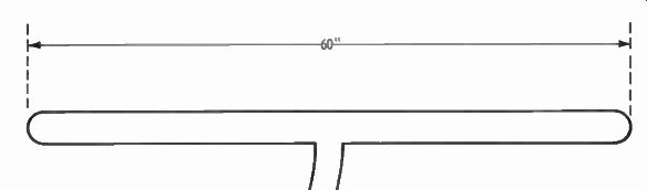
Fig. 4-1. Folded dipole.
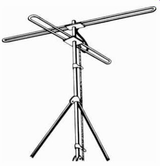
Fig. 4-2. Fm antenna with two folded dipoles.
The antenna illustrated in Fig. 4-1 would have a polar pat tern that would look like a figure 8 (Fig. 4-3). It would be good for pickup in the two opposite directions. The antenna of Fig. 4-2 is two folded dipoles at right angles to each other. The polar ...
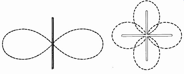
Fig. 4-3. Polar pattern of a single dipole. Fig. 4-4. Polar pattern of
two dipoles set at right angles.
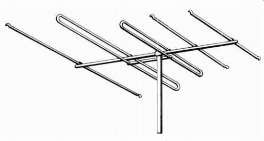
Fig. 4-6. Fm unidirectional antenna.
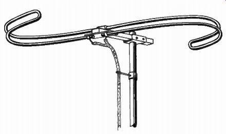
Fig. 4-5. S-curve, fm antenna.
... pattern becomes two figure 8's at right angles ( Fig. 4-4) . Now we have essentially an omnidirectional antenna. In practice the patterns illustrated are never exact, as they are affected by surrounding terrain and other conductive objects and overhead wire systems.
Fig. 4-5 is another omnidirectional antenna. As can be seen, the antenna is a single dipole but bent into an "S" curve. This will distort the normal figure 8 pattern and result in good omnidirectional pickup. The antenna of Fig. 4-2 is to be preferred for best all-around pickup.
If all fm services are in the same direction, or if you are some distance from the stations, the antenna shown in Fig. 4-6 is the best. It uses tv antenna engineering to achieve high unidirectional characteristics, using a reflector and two directors, in addition to the twin-drive elements shown. Its pattern is sharply unidirectional ( Fig. 4-7). This gives it the greater pickup sensitivity needed for reception at distances up to 110 miles.
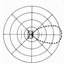
Fig. 4-7. Polar pattern of an fm uni-directional antenna.
STEREO RECEPTION AND ANTENNAS
If you have a good fm tuner or receiver you probably know it has a published sensitivity somewhere between 0.5 µV and 5 µV. This is a considerably higher sensitivity figure than for tv sets. This means that just about any old piece of wire connected to the antenna terminal will give you good enough reception, and often does. However, the better the signal into the tuner or receiver, the better the external and internal noise reduction and the better the reception quality.
This is even more important in receiving two-channel or stereo fm. The fm signal coming into your tuner not only carries the audio information, but includes a 19 kHz signal for use by the multiplex circuit in your tuner. This 19 kHz signal must lock-in with a 19 kHz signal developed in your tuner, or you won't get two-channel audio out. The 19 kHz signal is trans mitted at one-tenth the strength of the fm carrier itself. It is for this reason that you must have a good signal input to your tuner, if you want good lock-in with the multiplex circuit in your tuner.
Without a good signal you will lose two-channel reception or the stereo effect. With borderline signal input, the two-channel audio may go in and out as you listen, because changing atmospheric effects can vary the signal strengths. Without a good signal, you will have distorted audio. If you have an investment in good stereo equipment, don't ruin your enjoyment of good listening by neglecting the antenna.
In addition to its higher sensitivity, there are two other good reasons why the fm antenna of Fig. 4-6 is ideally suited for stereo fm reception.
While the fm band is not nearly as broad as a tv band, the 20-MHz bandwidth is equal to about three tv channels in a row.
A single antenna element will not cover the entire fm band with equal sensitivity. The antenna of Fig. 4-6 has two elements connected together, which gives it the name of twin-drive. Each element is a different size, engineered to provide equal signal pickup across the entire fm band. Whether the station is at the low, the middle, or the high end of the fm band, you can be assured of equal reception from any with stereo service.
As in the case of tv, multipath signal reception will affect the fidelity of the signal. When a signal from a secondary path, one reflected from a hill or water tower nearby for example, is received, the longer transmission path results in a slight delay in the signal. Depending on the length of the path, the delay can be partially or fully out-of-phase with the intended signal. An out-of-phase signal tends to act counter to the strength of the original signal and to cancel it to a degree. This reduced strength can affect audio quality in receiving stereo. As in the case of tv reception, a highly unidirectional antenna, such as the one of Fig. 4-6, is the answer.
What do you do if you want the advantages of a unidirectional antenna, but fm stations are all around you? The answer is use a rotator. In this way, you can swing the antenna toward the station you want to pick up and enjoy the best possible signal reception from it.
INDOOR ANTENNAS
Where conditions are right, an indoor antenna can bring quite satisfactory results. Conditions often found in smaller cities, such as fewer tall buildings to get in the way and fm transmitting towers fairly close to you, may not require the high antenna.
Fig. 4-8 is a cabinet-top indoor antenna with adjustable di pole elements, plus a multi-position switch for better impedance matching. The two "rabbit-ear" elements are telescoping, and so may be adjusted in length for best resonance to the fm frequency. A length of 300-ohm twin-lead line is included with the antenna. The rotatable base permits rotating the antenna for best pickup direction.
As in the case of the outdoor single dipole antenna, the pickup pattern is essentially a figure 8. The ideal figure 8 is achieved only when an antenna is assumed to be in free space.
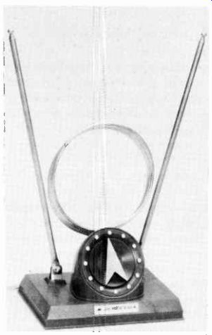
Fig. 4-8. Fm cabinet-top antenna.
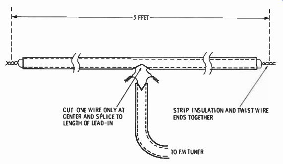
Fig. 4-9. Making an indoor fm antenna. 5 FEET; CUT ONE WIRE ONLY AT CENTER
AND SPLICE TO LENGTH OF LEAD-IN; STRIP INSULATION AND TWIST WIRE ENDS
TOGETHER; TO FM TUNER.
Free space means it is infinitely high, and there are no metallic obstructions anywhere near it. While this is not ideally achieved even in an outdoor antenna, it is far from achieved with an indoor antenna. Being indoors it is surrounded by conductive objects, such as the electrical wiring in the home, water and sewer pipes, gas pipes, and even the metal corner protectors used in plaster walls. Even the human body is a factor, especially since the height of a person is very nearly a half-wave long at the fm band. ( Remember the 60-inch length of a half wave dipole mentioned for fm earlier.) What does all this mean? It means there can be obstructions in the path of the signal that will reduce its strength. It means some of the signal can be reflected back to the antenna and either add to or subtract from the signal strength, depending on its distance from the antenna. It means a signal can vary as a person walks around the room. All of this means if you really want good fm reception, especially for stereo, use a good outdoor antenna.
For those who want to make their own indoor fm antenna, the sketch of Fig. 4-9 shows the details. A piece of 300-ohm twin lead is all you need. This antenna can be tacked behind the hi-fi cabinet, but results are better if it can be installed up higher, such as along the picture molding near the ceiling. Its position should be perpendicular to the path or direction of the principal fm station you want to receive.
INSTALLATION
Installation of an outdoor fm antenna is the same as for a tv antenna. A complete section on tv antenna installation is given later.
The coaxial cable mentioned for color-tv antenna installation is not needed for fm. However, 300-ohm twin lead can be used, and impedance matching is automatically achieved without transformers. It is important the line be kept clear of other metal objects, such as gutters, by the use of the same standoff insulators used for tv.
Next: FRINGE AREA TV/FM ANTENNAS
Prev: Link | --TV ANTENNAS
AMAZON multi-meters discounts
AMAZON oscilloscope discounts
Also see:
Industrial Electronics (in the early 1960s)
199 Electronic Test & Alignment Techniques (1972)