In order to evaluate new equipment and to localize and run down bothersome recording defects, a knowledge of testing techniques is essential. To properly test magnetic tape and tape recorders, a series of test instruments is required.
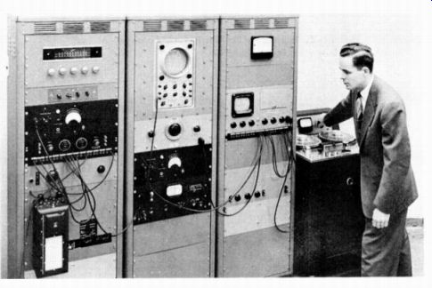
Fig. 11-1. A Typical Commercial Testing Installation.
The equipment need not be of expensive laboratory caliber as shown in Fig. 11-1. All test instruments required are relatively inexpensive and can conveniently be kept on hand in recording studios and broadcast stations. In addition, the advanced high fidelity enthusiast would do well to consider the addition of several test instruments to his gear in order to keep his recorder in peak operating condition.
Useful Test Instruments
Among the most useful test instruments is an audio oscillator capable of reproducing the audio range of frequencies. (See Fig. 11-2.) A good quality audio oscillator is not expensive. There are audio oscillators, available, in kit form, for as low as $25.

Fig. 11-2. Typical Audio Oscillator. (Courtesy of Jack son Electrical
Instrument Co.)
Fig. 11-3. An AC VTVM with a Db Scale. (Courtesy of Hickok Electrical Instrument Co.)
An output meter such as shown in Fig. 11-3 is also on the "must" list of necessary test instruments. Most volt-ohmmeters have a db scale which serves satisfactorily. The output meter should read essentially flat over the audio range and can be calibrated against the audio oscillator. If the output meter reads 2 db higher at 10,000 cycles than at one thousand cycles, the 2 db should be subtracted in frequency runs. The error in the meter must also be taken into consideration when making measurements.
In addition to an audio oscillator and an AC meter for reading output, a measuring device is needed to determine distortion. There are available several excellent inter-modulation distortion measuring devices selling in kit form for slightly under $50. Other precision inter-modulation measuring instruments of laboratory quality sell upwards of $500. However, it is possible to make highly accurate harmonic distortion measurements with a filter selling for approximately $20. In the distortion tests to be discussed later in the section, it is assumed that the filter method of measurement will be used. A filter can be used in two ways. First, the filter can be used to reject the signal being recorded, thus passing only the harmonic products. Or, second, the filter can be used to pass only the desired harmonic product, rejecting all other frequencies. In other words, one may use a filter as a rejection device, rejecting the signal being recorded and passing all harmonics, thus reading total harmonic distortion. Or, a filter may serve as a pass filter, used to pass only the harmonics being measured, enabling one to check 2nd and 3rd harmonic distortion independently.
Testing Magnetic Tape
In testing a Magnetic tape recorder, one is, in reality, testing two things: the magnetic recording tape and the recorder itself. Magnetic tape is an inseparable part of the recording process. Therefore, in order to realistically test a recorder, it is essential to understand and evaluate certain important characteristics of the tape.
The backing, the magnetic oxide coating, the binder, the plasticizer, the lubrication, when combined in finished form, produce a magnetic tape. In testing a magnetic tape, all tape properties can be divided into two main classifications: (1) physical properties of the tape; and (2) magnetic properties of the tape.
In properly evaluating the performance of magnetic tape, all physical and magnetic properties must be considered since each affects performance of a tape.
Physical Characteristics of Magnetic Tape
The physical characteristics of magnetic recording tape must be evaluated in any testing procedure. Of a tape's physical properties, it is important to know what is the strength of a particular backing material. Under a given tensile force, what is its break point? What it its yield point? Tape should have a reasonable strength so that it will not break easily. However, practically all tape breakage is caused by nicks on the tape edges rather than the tape being pulled apart. The tensile strength of most acetate-backed tapes is approximately 5.5 pounds, while the operating tension exerted by a recorder is seldom more than a few ounces. However, since the strength of acetate is equivalent to its edge strength, any nick or tear on the tape's edge represents a potential break point. The nicks generally occur during thread-up of the recorder. Care should be taken to place the tape in the recording mechanism properly.
Another important property of magnetic tape is that the oxide adhere firmly to the base, not rubbing or flaking off. Some tape constructions have been known to become brittle and flake off with the passage of time. Most present-day tapes, however, have been greatly improved in this respect.
Other factors that affect a tape's performance are cupping and curling. When the tape is subjected to high temperature and humidity, will the tape remain flat or will it tend to curl or cup? Poor tape, under high humidity conditions will tend to curl, thus making poor contact with the record head. Poor head contact results in the loss of high frequencies and serious amplitude variations.
What is the layer-to-layer adhesion of a tape? Can one turn of the tape be freely pulled from the next or will the layers tend to stick, indicating an adhesive, sticky binder material or excessive smoothness of the surface? Squealing will occur when the tape actually becomes gummy, sticking to the magnetic head intermittently with a staccato effect. The squeal is picked up and reproduced in the record and playback process with a very disconcerting effect. Most present-day tapes are especially lubricated, a treatment designed to prevent squealing.
Tests of Physical Properties
The following tests are typical of those used in testing laboratories in evaluating tape constructions. Each test is but one method (although in all cases not necessarily the best way) of measuring a specific tape property.
The backing material: The backing material is determined by visual inspection and chemical analysis. The strength of the material, stability, and smoothness are then determined.
Tensile strength: The tensile properties are measured with a Scott inclined-plane tensile tester. (See Fig. 11-4.) The result is the tensile stress in pounds required to break the tape.
Blocking: The test for layer-to-layer adhesion (blocking) consists of tightly winding several layers of tape on a stainless-steel mandrel and subjecting this sample to a 16-hour conditioning at 130° F., 90% relative humidity. The tape is then subjected to a 4 hour cycle at 130° F., and 0% relative humidity, and finally allowed to return to room conditions. When cooled, the tape is unwound and inspected for adhesion between layers and transfer of the oxide coating to adjacent layers. This test simulates the effect of natural aging and humidity cycling on layer-to-layer adhesion.
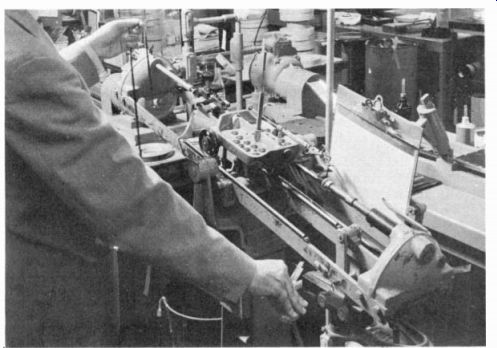
Fig. 11-4. The Scott Inclined-Plane Tester Shown Here is Used to Test
the Tensil Strength of the Tape Backing.
Curling: In the curling test, small samples of the tape are placed in each of two chambers having relative humidities of 0% and 85%. The samples are viewed "end on" and the angle of curvature is accurately measured.
Anchorage: To test for coating anchorage to the base, the oxide coating is stripped off with pressure-sensitive adhesive tape. The degree of removal indicates the firmness of the bond between the coating and the backing. Another simple test for oxide anchorage is to pinch the tape between the figures and roll it sharply, indicating whether the oxide has good adhesion to the base.
Caliper: Tape thickness is measured on special callipering devices which measure accurately to the hundred-thousandth of an inch.
Evaluation of Magnetic Properties
Here are the magnetic properties of a tape and how they can be measured and evaluated: Output for 1% distortion: The output of a magnetic tape is generally determined by the coating thickness or, through newly perfected techniques in magnetic tape construction, by improved formulations which increase the density of the oxide coating without adding to tape thickness.
The output test for 1% third-harmonic distortion is made on a professional recorder adjusted at peak bias for the tape under test. A 1000-hz signal is recorded on the tape. The input signal strength is increased until the output signal is 1% distorted (3rd harmonic). This output is the maximum obtainable before seriously overloading the tape. A high output for a given distortion is essential in obtaining a good signal -to-noise ratio.
Sensitivity: The sensitivity of a tape is a measure of how much output or signal is obtained from the tape for a given input. This is generally measured on a comparative basis. For example, tape of two manufacturers are spliced end for end. A given signal at low or middle frequencies is applied, well below the distortion or overload region of the tape.
After measuring output at 1% third-harmonic distortion, the 1000-hz input signal strength is reduced to a standard value, fixed at a point well below 1% distortion for all tapes. The output of a given tape for this fixed input is, then, a measure of the tape's sensitivity. A tape with high sensitivity is desirable since it requires a minimum of recording signal power to obtain full output.
The output is observed for each of the tapes. If one tape has 2 db more output then the other tape, then that tape is said to be 2 db more sensitive.
It is vital that tapes have the same sensitivity, especially when the tapes are spliced together. To cite an example of the seriousness of the problem, let us assume two tapes of varying sensitivity are spliced together. One tape may be 4 db less sensitive than the other. When recording at full band, suddenly there will be a drop of 4 db in the volume when the less -sensitive tape passes the magnetic record-reproduce head.
Tape distortion: Another measure of a tape's performance is its output for a given distortion. As explained in the section on amplifiers, the tape itself introduces only third-harmonic distortion. The amplifier, however, will introduce both even and odd harmonic components. Generally, second and third harmonics are the strongest. However, if there are any magnetized regions on the recorder such as magnetized heads, the tape will introduce second-harmonic distortion.
Using a filter measuring device, the measure of a tape's output for a given distortion is determined as follows: A middle or low frequency signal (between 500 to 1000 cycles) is recorded on the tape. The amplitude of the signal is slowly increased until its distortion reads a fixed value, 3%. Then the output from the tape is observed at this point.
Frequency response: Still another test of a tape's magnetic properties is its frequency response. This is, in reality, a measurement of a tape's sensitivity at different frequencies. For example, on a given recording mechanism one tape reproduces the same output at a high frequency, say 10,000 cycles, as at 1,000 cycles. A second tape may reproduce 2 db less output at 10,000 cycles as at 1,000 cycles. The second tape is said to have 2 db less output at 10,000 cycles when compared to the standard reference test tape.
With the input signal level set below the 1% distortion point by the amount of pre-equalization used in the recorder (input at least 15 db below "0" level for most recorders at 15 ips), the output for a 1000 hz and a 15,000 hz signal is noted. When the low-frequency output in db is subtracted from the high-frequency output the result represents either the loss or gain in output of the tape at high frequencies. A good output at high frequencies is a "must" for high fidelity recordings and for machines operating at slow tape speeds.
Noise level: Generally the easiest method of reading noise is to hold a strong permanent magnet against the tape. By playing the tape at a fixed gain setting of the playback amplifier, the overall DC noise is measured. The noise figure indicates the amount of modulation noise contributed by non-uniformities on the coated surface of the tape.
Uniformity: To test for uniformity, again using a 1000-hz input signal which is held at a constant level, the recorder's output is observed on a meter. Careful watch should be kept for the maximum output deviations. On present-day recording tape, the sensitivity should not vary more than a quarter of a db within a reel and not more than a half of a db from reel to reel. A more exact measurement may be made by feeding the recorder's output to a magnetic pen-motor with good response up to 50 or 100 hz. The uniformity is then taken as the average output variation in db over the length of tape wound on the reel.
Coercive force and remanent flux: The magnetic tests for coercive force and remanent flux are made on a dynamic hysteresis curve tracer, a laboratory instrument. The coercive force largely determines the signal strength required to record or erase the tape. The tape's remanent flux indicates the approximate signal output.
Testing a Recorder
Frequency response: The most common measurement made of a recorder's performance is the frequency response test. This is the most common test of a recorder, perhaps,, because it is the easiest test to make and is generally indicative of a recorder's over -all performance.
A good recorder will have what is known as a reasonably flat response. That is, over a given range of frequencies, the output will vary only a small amount. There will be no sudden drops of output
at certain frequencies or rises in output at other frequencies. Professional recording equipment is often flat to within one or two db over the entire audio range from 30 to 15,000 cycles. In contrast, some home recorders may vary as much as 6 to 10 db over the range of 70 to 8,000 cycles.
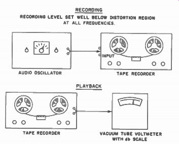
RECORDING LEVEL SET WELL BELOW DISTORTION REGION AT ALL FREQUENCIES Fig. 11-5. Method of Measuring Frequency Response of a Tape Recorder.
To measure frequency response, the audio oscillator is connected to the input of the recorder as shown in Fig. 11-5. Its amplitude is set so that the signal level recorded on the tape is down by at least the amount of pre-equalization used in the recorder (generally 15 db below the normal record level).
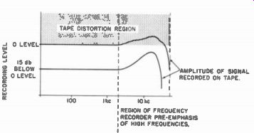
Fig. 11-6. Disadvantage of Taking Frequency Response Checks at a High
Volume Setting.
Magnetic tape overloads at approximately the same amplitude regardless of frequency. Since most recorders often boost the high frequencies during recording, the frequency run must be made at a low enough level so that the high frequencies will not be boosted to a point where they will overload the tape. If, when making a frequency response measurement, the record level is set too high, the high frequencies in the region of pre-emphasis will overload the tape and will not be reproduced properly. A tape recorder with normally excellent frequency response would then appear to have very low output at high frequencies. As shown in Fig. 11-6, the record level for frequency response checks should be made at least 15 db below 0 level for most machines. That is, if in the equalization process the high frequencies are boosted by 15 db, when making a frequency response test, one must record at 15 db below the normal recording level. This must be done to avoid overloading the tape at high frequencies. The audio oscillator is then varied over the frequency band, and the output is noted and recorded on the AC voltmeter or output meter. It is necessary that the output meter be calibrated in terms of db since this is the unit of measure generally used in specifying recorder performance.
Signal-to-noise ratio: Another important test of a recorder's performance is the determination of the signal-to-noise ratio. This is generally a test of the maximum distorted output, taken as 3 percent total harmonic distortion, compared to the noise from the amplifier with erased tape. To perform this test, one should have a rejection filter. The filter should be calibrated in terms of number of db rejected at a certain frequency. Generally, a rejection filter of 400 cycles is satisfactory.
The audio oscillator is again connected to the input and a 400 cycle tone is fed to the recorder. The signal from the recorder is then fed into the filter, thus rejecting the 400 cycle or fundamental. The output from the filter then represents the harmonic products. However, care should be taken to subtract any fundamental that is passed by the filter.
The tape output is then set to give 3 percent harmonic distortion. The output at this point is then observed. Next, cleanly erased tape is played back on the same machine, and the noise is noted.
The difference in output between the 3 percent point and the noise level is the signal-to-noise ratio of the recorder.
Professional recording equipment often has a 60 db or better signal-to-noise ratio. On home-type recorders, a figure of 40 db is often considered good.
Flutter and wow: Still another test of a recorder is for flutter and wow. To accurately express the amount of flutter and wow in a percentile generally requires an expensive flutter and wow meter. However , one can get along without this costly laboratory measurement device. The human ear is most sensitive to flutter and wow around three thousand cycles. Therefore, to measure flutter and wow, it is well to record a signal of approximately 3,000 cycles and then to play it back, listening carefully. Any flutter and wow at 3,000 cycles can be easily discerned. With a little practice, one can quickly judge what is acceptable and unacceptable. Generally, if only a slight amount of flutter and wow can be discerned the recorder is operating properly. If the amount is noticeable or irritating, chances are that the recorder has an excessive amount of flutter and wow.
Distortion: To measure Distortion in a recorder, the output is passed through a rejection filter, and the distortion products are read for a given output level.
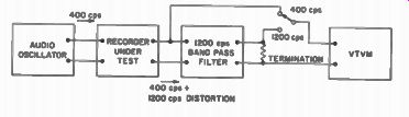
Fig. 11-7. Block Diagram of a Distortion-Measuring System.
The equipment required for distortion measurement is an audio oscillator with good waveshape, a vacuum tube voltmeter capable of reading over a fairly wide range of voltage, and a bandpass filter. A block diagram of this method is shown in Fig. 11-7. Since it is customary to measure distortion at 400 hz, a 1200 hz bandpass filter is ideal for measuring third harmonic distortion. The filter should have a rejection of at least 60 db at the fundamental test frequency (400 hz) if highest accuracy is to be obtained.
Before making the test it is necessary to calibrate the system to take into account the insertion loss of the filter. Since the input determination will affect this value, it is best to calibrate the filter from the actual recorder under test. To do this, the filter is disconnected and the output level of the recorder checked at 400 hz and 1200 hz to determine if it is the same at these frequencies. If not, ...
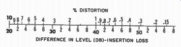
% DISTORTION; DIFFERENCE IN LEVEL (DB)-INSERTION LOSS
Fig. 11-8. An Alignment Chart for Converting Decibels to % Distortion.
... the input to the recorder must be readjusted at one of the frequencies to compensate for this discrepancy. The filter is then connected to the recorder, and a level reading taken at 400 hz at the input to the filter. The oscillator is then set at 1200 hz and the level is read at the output of the filter. (The input level to the recorder must be readjusted if necessary as previously determined.) The difference between these readings in decibels is the insertion loss of the filter.
In making a distortion measurement test, a 400 hz signal is fed through the recorder and level readings taken at both the input and output of the filter. The difference between these readings in db minus the insertion loss of the filter is the true ratio between the signal and the third audio harmonic component. This can be converted to percent by reference to the alignment chart given in Fig. 11-8.
Other recorder tests: In addition to the performance tests of a recorder, care should be taken to see that the mechanism functions smoothly. Tape must not spill off the reel during fast forward and rewind. The drives must engage smoothly and evenly. The recorder must be relatively quiet in respect to mechanical noise.