I-F Amplifiers
To a major extent, the i-f amplifiers used in an fm receiver determine the overall gain and selectivity of the receiver.
Two stages of amplification, in which three double-tuned transformers are employed, are generally used. To secure the required broad-band response, the Q of the i-f transformer windings is made comparatively low. In addition, one or more of the transformers is often overcoupled to broaden its response. The i-f frequency used in most modem fm broadcast receivers is 10.7 MHz. This high intermediate frequency gives excellent rejection of image-frequency interference.
Integrated-circuit units provide excellent results in small space for modem i-f amplifier assemblies. Integrated circuits include a number of types that are essentially subsystems designed to replace several discrete-component stages in specific types of applications.
Such circuits are designed to provide multiple functions in specialized hi-fi applications. Certain integrated circuits are designed especially for use in the i-f sections of broadcast receivers. These units are basically wide-band amplifier-limiter circuits intended for use with external fm detectors. Others can provide high-gain i-f amplification, noise limiting, fm detection, and low-level audio amplification in fm receivers without the use of external components other than tuned coupling networks and bypass elements.
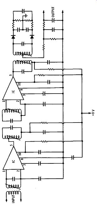
Fig. 4-43. Integrated-circuit i-f amplifier for fm.
Fig. 4-43 shows a schematic diagram of an integrated-circuit i-f section for an fm stereo receiver. Each IC consists of three direct coupled cascaded differential amplifier stages and a built-in regulated power supply. Each of the cascaded stages consists of an emitter follower. The operating conditions are selected so that the de voltage at the output of each stage is identical to that at the input to the stage. This condition is achieved by operation of the bases of the emitter-coupled differential pair of transistors at one-half the supply voltage and selection of the value of the common emitter load resistor to be one-half that of the collector load resistor. As a result, the voltage drops across the emitter and collector load resistors are equal, and the collector of the emitter-coupled stage operates at a voltage equal to VBE plus the common-base potential.
The potential at the output of the emitter follower, therefore, is the same as the common-base potential.
The integrated circuits in Fig. 4-43 are designed to operate at various levels of de supply voltage up to 7.5 volts. Others, which have higher supply-voltage and dissipation ratings, may be operated at de supply voltages up to 10 volts. For each circuit, the external de voltage is applied to terminals 10 and 5; de voltages required at other terminals are derived from the internal power supply. When the circuits are operated at the same de levels, the characteristics of their amplifier limiter stages are identical. For operation at 7.5 volts with an ac resistive load impedance of 3000 ohms from terminal 5 to ground, the output voltage at terminal 5 with respect to ground is typically 3 volts peak-to-peak.
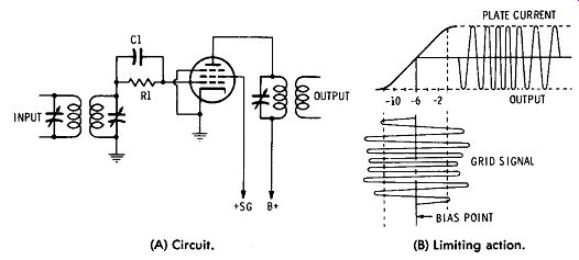
(A) Circuit. (B) Limiting action.
Fig. 4-44. A typical limiter circuit.
The performance of these integrated circuits in the i-f amplifier limiter section of an fm radio receiver is at least equal to that of conventional circuits in every characteristic, and is superior in many of them. In particular, the a-m rejection ratio ( more than 50 dB) of the integrated circuits is so large that it cannot be measured with commercial fm-am signal generators because of incidental phase modulation of the generators.
Limiters--In receivers using discriminator-type detectors, some means must be provided to remove amplitude variations from the received signal before it is applied to the detector stage. The function of the limiter is to remove noise pulses and to restore uniformity to the signal over the passband. A simplified limiter circuit is shown in Fig. 4-44A. A sharp-cutoff tube is used. The plate and screen voltages applied to the tube are much lower than those normally applied to an amplifier, and no fixed bias is provided. Bias is obtained by placing a capacitor and resistor in the grid return of the tube. Under these operating conditions, a grid signal of comparatively low amplitude will drive the tube to saturation on positive peaks, and to cutoff on negative peaks.
This action is illustrated in Fig. 4-44B. When the input signal to the limiter has sufficient amplitude, all the negative and positive peaks are clipped, and the signal at the plate of the limiter has a constant amplitude. If the signal is not of sufficient amplitude, only partial limiting will take place. Resistor R1 and capacitor C1 play an important part in the operation of the limiter. During the positive half cycles of input voltage, the grid of the tube draws current, loading the input tuned circuit and providing a diode clipping action.
During this period, there is current through resistor R1, and capacitor C1 is charged. During the negative portion of the input-signal cycle, C1 discharges through R1, developing a negative grid bias which is proportional to the amplitude of the input signal. When the amplitude of the input signal increases, the bias on the tube becomes more negative. Thus the bias on the tube is automatically controlled by the amplitude of the input signal. The time constant of R1 and C1 is chosen so that it is long enough to maintain substantially constant grid bias during the negative portions of the i-f signal applied to the stage. However, the time constant is short enough to permit an increase in bias when sudden amplitude impulses occur.
In hi-fi receivers, two limiter stages are recommended to secure proper limiter action.
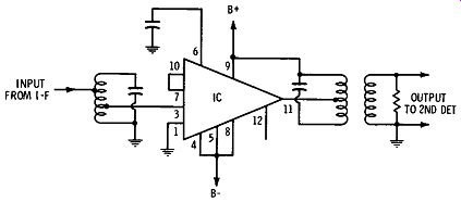
Fig. 4-45. Integrated-circuit limiter.
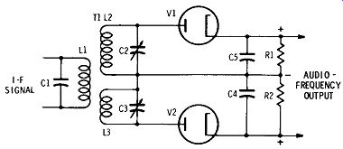
Fig. 4-46. A double-tuned discriminator circuit.
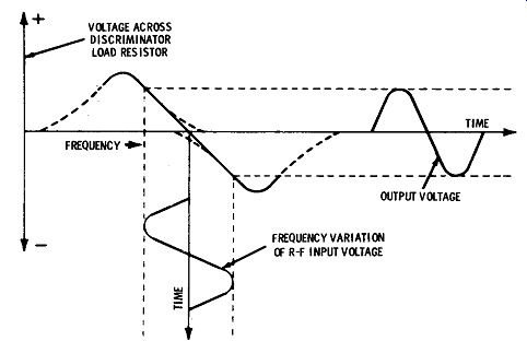
Fig. 4-47. Discriminator response curves.
An integrated-circuit limiter is shown in Fig. 4-45.
Discriminators--The discriminator circuit of Fig. 4-46 illustrates one way in which the audio modulation may be removed from the frequency-modulated carrier. The i-f signal is coupled to the discriminator plates by means of transformer T1. The secondary of the transformer consists of two windings, L2 and L3, tuned by means of capacitors C2 and C3. Tuned circuits L2-C2 and L3-C3 are resonated at different frequencies, one above the frequency of the received signal and the other below it. The frequencies to which the resonant circuits are tuned are equal to the carrier center frequency plus the maximum rf carrier deviation, and the carrier center frequency minus the maximum rf carrier deviation. For fm broad cast reception, one tuned circuit is tuned to the carrier center frequency plus 75 kHz, and the other to the carrier center frequency minus 75 kHz.
Fig. 4-47 illustrates the response curves of the tuned circuits as indicated by the voltages at the plates of the diodes. When a frequency-modulated signal is applied to the input of the circuit, the instantaneous voltages on the diode plates vary as the signal swings each side of the center frequency. If L2 and C2 are resonant above the carrier frequency, the voltage on the plate of V1 will be higher than the voltage on the plate of V2 when the carrier swings higher in frequency than its center frequency. When the carrier swings lower in frequency than its center frequency, the voltage on the plate of V2 will be higher than the voltage on the plate of V1. When the carrier frequency is above its center frequency and the voltage on the plate of V1 is higher than the voltage on the plate of V2, the current through V1 is greater than the current through V2; consequently, the voltage developed across R1 is greater than the voltage developed across R2. The resistors are connected so that the voltages developed across them are of opposite polarities. Under the conditions described, the voltage at the output is positive. When the carrier swings below its center frequency, the voltage developed across R2 is greater than that across R1, and the voltage at the output of the circuit is negative in polarity. Thus, as the carrier swings above and below its center frequency, it produces a voltage in the output of the discriminator which varies in accordance with the modulation of the fm carrier.
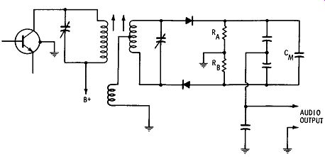
Fig. 4-48. A ratio detector circuit.
Other FM Detectors--The ratio-detector circuit shown in Fig. 4-48 is a discriminator circuit which is relatively insensitive to amplitude variations ( a-m) in the fm signal. The phase-shift relationship of the voltages in the tuned transformer results in a detected signal output that varies in direct proportion to the variations in frequency of the fm signal. In the ratio detector, the diodes are arranged back to-back rather than push-pull so that both halves of the circuit operate simultaneously during one half of the signal-frequency cycle, and both are cut off on the other half cycle. As a result, the rectified voltages from the two diodes are in series. When the audio output is measured across the capacitor, the output voltage is equal to the addition of these voltages.
The dc circuit of the ratio detector follows a path through the secondary winding of the transformer, both diodes, and resistors Ra and RB, This circuit provides improved a-m rejection as compared with the discriminator circuit shown in Fig. 4-46.
The integrated circuit in Fig. 4-49 includes a high-gain i-f amplifier-limiter, an fm detector, an audio preamplifier-driver, and a zener-diode-regulated power supply on a single monolithic chip.
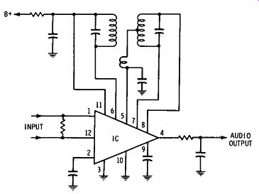
Fig. 4-49. Integrated circuit used as limiter, fm detector, and audio
amplifier in receiver.
This circuit is designed for use as a major subsystem for the i-f sections of high-fidelity fm receivers. This unit is supplied in a 12 terminal TO-5 type package and operates over a temperature range of -55° C to + 125° C. The four-stage emitter-coupled i-f amplifier-limiter section of Fig. 4-49 provides a voltage gain of 80 dB at 10.7 MHz. The output stage of this section provides exceptional limiting characteristics, which can be attributed to its use of a transistor constant-current source. The fm detector section is distinguished by circuitry which provides forward bias to the detector diodes and also provides a reference voltage for automatic frequency control ( afc). The audio preamplifier-driver provides a low-impedance drive for subsequent audio amplifiers. The power-supply section provides zener-diode regulated, decoupled voltages for the i-f amplifier, detector, and audio-amplifier sections.
This integrated circuit is designed to operate from a dc supply voltage of +30 volts applied to terminal 11 through a 750-ohm resistance. Terminal 11 may be connected to any positive voltage source through a suitable resistor, provided the maximum dissipation limit or any of the maximum voltage or current limits for the circuit is not exceeded.
Tuner Compensation
Re-emphasis and de-emphasis are used in standard fm broad casting and reception to minimize noise at the receiver. The high frequency portion of the audio modulating signal is purposely boosted at the transmitting station to a relatively higher level than the remainder of the audio-frequency range. This is known as pre-emphasis. Then, at the receiver, the exact reverse of this is done, to restore the high audio-frequency components to their normal relative level. This is known as de-emphasis. The advantage is that in the de-emphasis process, the reduction of relative response to high frequencies also reduces the response to noise. The standard pre-emphasis and de-emphasis characteristics are shown in Fig. 4-50. The Dolby system of noise reduction provides a distinct improvement in sound quality of fm broadcasts in the effective range of the fm station. Dolby A and B systems take advantage of the psycho acoustic phenomenon called masking. They use an advanced technique similar to the pre-emphasis and de-emphasis operations shown in Fig. 4-50, except that only a portion of the signal is emphasized and de-emphasized, and only under certain conditions.
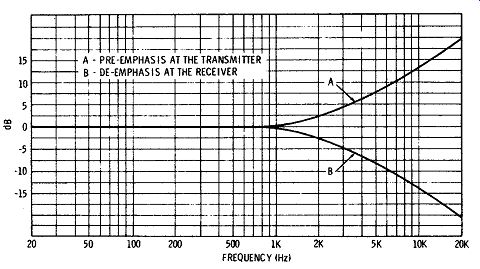
Fig. 4-50. Standard fm pre-emphasis and de-emphasis characteristics.
To the listener, the louder sounds cause the ear to respond mainly to them and to conceal the presence of softer sound. To produce a Dolbyized signal, the station processes the signal by analyzing the music and automatically increasing the strength of quiet musical passages, mostly in the upper frequency ranges. This produces a signal level of these lower-strength passages of music that is in proportion to the combined undesired background noises of the equipment and the atmospherics so that the desired signals stand out and are no longer obscured.
The masking effect does not occur when the sounds are of different pitch. For example, the sound of a piano will not mask the sound of a violin.
The de-emphasis circuitry in the receiver must contain Dolby licensed circuits to reverse the process, by analyzing the sounds that have been emphasized and automatically de-emphasizing them in amounts equal to the emphasis made to each frequency at the broad cast station. Receivers designed to process these kinds of signals are now available ( Section 5). For a further discussion of the Dolby system, see Fig. 4-69 and related text.
Stereo Tuners
As explained in Section 3, tuners for stereo are similar to those for monophonic reception, but with differences as follows:
1. The original method of stereo broadcast and reception used separate a-m and fm channels. Two separate tuners were used for stereo, one for amplitude modulation and one for frequency modulation. Both a-m and fm facilities were available in hi-fi tuners before the advent of stereo and were employed as a means of carrying the two channels without new techniques or equipment. For stereo, the tuners were completely separate, so that both were played at the same time for am/fm two-station stereo reception.
2. Provisions are now made for reception of multiplex signals with fm tuners. This consists of providing a separate "multiplex" output for feeding to a multiplex adapter, which is integrated in the receiver or may be bought separately.
The specifications important in the selection of tuners for mono phonic reception as discussed up to this point apply also to tuners for stereo reception. In the use of stereo-type tuners for two-station reception, the output of the a-m section was one stereo signal, and the output of the fm tuner was the second stereo signal. These out puts were simply connected to separate channels in the stereo pre amplifier. For multiplex reception, the regular fm tuner output and the multiplex ( mx) fm tuner output are both connected to the multiplex adapter; the adapter then delivers the left and right signals to the preamplifier.
Some examples of combination tuner units are illustrated in Fig. 4-51.
Combination tuners and dual preamplifiers allow such functions as volume, bass and treble boost, and stereo balance to be controlled on the same panel as the tuner dial. Only a two-channel amplifier and speaker system need be added with such an arrangement.
Sometimes the combination process is carried one step further and the tuner, preamplifier, and amplifier are all combined. Such units include everything needed for reception of stereo broadcasts except the speaker system. Examples of these combinations are shown in Section 5.
Courtesy Lafayette Radio Electronics Corp.
(A) Lafayette LT-725 am/fm tuner. Courtesy Acoustic Research, Inc.
(C) Acoustic Research fm tuner. Courtesy Heath Co.
(E) Heathkit AJ-1510 digital fm tuner. Courtesy McIntosh Laboratory, Inc.
(B) McIntosh MR 73 am/fm tuner. Courtesy Electro-Voice, Inc.
(D) Electro-Voice E-V 1255 fm tuner. Courtesy Marantz Co., Inc.
(F) Marantz Model 20 fm tuner.
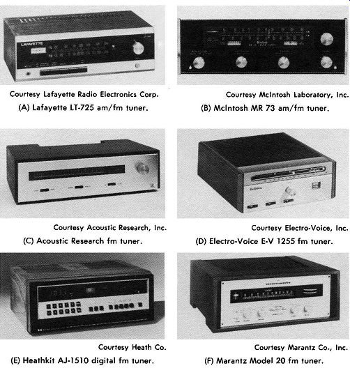
Fig. 4-51. Some fm and am/fm tuners.
Stereo Multiplex Adapters
A typical multiplex adapter unit is illustrated in Fig. 4-52. This kind of unit can be connected to any tuner to provide am multiplex reception. Fig. 4-53 shows an adapter that mounts directly on the receiver chassis, making it an integral unit suitable for a-m and f-m multiplex outputs.
A block diagram of a typical am tuner with multiplex is shown in Fig. 4-54. From the antenna through the main detector and de-emphasis network, it is the same as a non-stereo tuner.
The high-pass filter, demodulator, and matrix portion of Fig. 4-54 is often referred to as the stereo converter or stereo translator. It can be connected to a non-stereo tuner to provide stereo output, if the received signal is transmitted as multiplexed stereo. The multiplex input of the converter is connected to the "multiplex" output of the tuner detector, before the de-emphasis network. The shielded ...
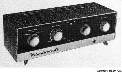
Fig. 4-52. An adapter to convert early tuners for reception of fm multiplex.
Courtesy Heath Co.
... lead between the multiplex jacks on the tuner and the converter should be kept as short as possible, to avoid undue attenuation of the subcarrier.
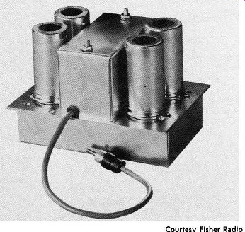
Fig. 4-53. A plug-in stereo multiplex adapter. Courtesy Fisher Radio
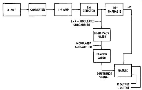
Fig. 4-54. Block diagram of a typical tuner equipped with a multiplex
converter.
Stereo Multiplex Operation
As explained in Section 3, stereo multiplex is the system whereby the left- and right-channel signals of a stereo program are both sent out on one fm broadcast channel. In the method standardized in the United States by the Federal Communications Commission, the following objectives are attained:
1. The left ( L) and right ( R) signals are sent, in separable form, within the 200-kHz fm broadcast channel bandwidth.
2. Both signals are modulated onto the same carrier with negligible loss of signal-to-noise performance compared with that of monophonic transmission. This is accomplished by means of the "interleaving" provided in the system.
3. The system is compatible in that the owner of an fm receiver not equipped for stereo reception still receives an L + R signal equivalent to that received from non-stereo broadcasts.
Sum and Difference Signals--Although the L + R signal is all the listener to a monophonic program needs, the proper reception and reproduction of stereo programs requires the use of an additional ( L-R) signal. This signal is produced at the transmitter by inverting (phase changing-by 180 degrees) the R signal (making it negative, or - R) and adding it in its negative form to the L signal. The resulting L - R signal, as well as the L + R signal, is transmitted on the fm broadcast carrier. The two signals are received and separated at the receiver. Then, in the stereo receiver, they are added together to form the L signal alone, and the L - R signal is subtracted from the L + R signal to form the R signal alone. This is shown mathematically as follows:
L+R+ (L-R) =L+L+R-R=2L R+R-(L-R) =L-L+R+R=2R
Stereo Multiplex Modulation Signal--The L +Rand L - R signals are both sent as part of the signal which frequency modulates the main (radio-frequency) carrier. Before we proceed with details of the modulating signal, it will minimize confusion to emphasize a very important fact: As far as the main carrier of the fm signal is concerned, there is only one composite modulating signal, all of whose components modulate the carrier. The composition of this modulating signal includes the L + R signal, a signal conveying L - R information, and certain other components.
The spectrum of the modulating signal is shown in Fig. 4-55. Its bandwidth is from 50 Hz to 75 kHz. The lowest portion of the modulating-signal spectrum extends from 50 Hz to 15 kHz, and this range includes the components of the L + R signal, or the signal that corresponds to or may be used as a normal monophonic modulation signal. In other words, if we remove all the signal components of frequencies above 15 kHz, we have a signal similar in effect to those signals used before stereo multiplex was developed.
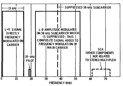
Fig. 4-55. Frequency spectrum of frequency-modulation signal on main
carrier.
Next in the spectrum is a 19-kHz pilot signal. However, let us ignore this for the moment and proceed to the L - R portion of the signal, extending from 23 kHz to 53 kHz except for a 100-Hz quiet spot in the middle. This region consists of the sidebands resulting when the L - R signal modulates the 38-kHz subcarrier. At the station, after the modulation has taken place, the 38-kHz subcarrier is suppressed, and only the sidebands are used. Since the carrier component was at 38 kHz, and since the L - R signal contains frequencies from 50 Hz to 15 kHz, the L - R signal sidebands ex tend from 23,000 Hz to 37,950 Hz, and from 38,050 Hz to 53,000 Hz.
These sidebands are added to the modulating signal. In relation to the main carrier, all frequencies in this composite modulation of the main carrier are above audibility, so they do not interfere with transmission and reception of the main-carrier L + R signal for the listener using a monophonic receiver.
The L - R sidebands as an independent signal are not intelligible in the form in which they appear in the modulation signal. They must be: ( 1) recombined with a 38-kHz carrier, ( 2) demodulated from that carrier, and ( 3) decoded.
To process the signal at the receiver, the composite frequency modulation signal depicted by Fig. 4-55 must be demodulated from the main carrier, and the L + R signal and the L - R sidebands must be separated from the other parts of the signal by filters.
Demodulating the L - R Signal--The carrier with which the side bands are combined at the receiver must have the desired 38-kHz frequency within very close limits and remain synchronized to pre vent distortion when these sidebands are demodulated. The desired synchronization is provided by the 19-kHz pilot carrier added to the modulation signal. This steady 19-kHz unmodulated signal is demodulated from the main carrier at the receiver and passed through a frequency doubler, whose output at 38 kHz is combined with the L - R sidebands to produce the L - R signal. The output from the doubler may be used directly for combining with the sidebands, or, as in some designs, this output can be used to synchronize a 38-kHz oscillator whose output is in turn used to combine with the sidebands.
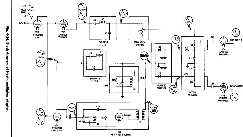
Fig. 4-56
When the 38-kHz subcarrier has been combined with the L - R signal sidebands, the result is an amplitude-modulated signal. In some stereo receivers ( or adapters) this signal is demodulated by an ordinary a-m detector to obtain the L - R signal. The L - R signal is then matrixed with the L + R signal ( as explained earlier)
to obtain the separate L and R signals. In another method of detection, the local 38-kHz subcarrier is used as a switching signal, connecting the output of the main fm detector to the L output channel and the R output channel during alternate 38-kHz half cycles.
Stereo Adapter Circuits--A diagram of a typical stereo adapter is shown in Fig. 4-56. The adapter obtains its signal input from the "stereo" output of an fm tuner; this output is simply the "audio" output of the tuner, tapped off at a point in the circuit before the de-emphasis network. This output from the tuner is applied to the first stage in the adapter, which is a wideband amplifier. This amplifier amplifies all the frequency components in the tuner output, which include the L + R signal (already in audio form), the 19-kHz pilot signal, and the L - R sidebands. Also included in some cases is another signal, called the Subsidiary Communications Authorization (SCA) signal, which, as indicated in Fig. 4-55 is centered around 67 kHz. This signal, which is used for commercial "store casting" service, has nothing to do with home fm reception, and it is filtered out in the adapter circuits-so we shall ignore it.
In the circuit illustrated, the wideband amplifier uses a tube. Its signal output is applied to three paths: ( 1) a low-pass filter (inductor and capacitors) which removes frequency components above 15 kHz, leaving just the L + R signal, ( 2) a bandpass filter and trap, which pass only the L - R sidebands, and ( 3) a 19-kHz keyed oscillator-doubler which doubles the frequency of the 19-kHz pilot carrier. The oscillator-doubler locks in frequency and phase to the amplified pilot signal, and provides a 38-kHz signal for the L - R detector.
The detector uses two solid-state diodes connected in opposite polarities. The 38-kHz and L - R sideband signals are both applied to the detector, where they combine and then undergo demodulation. Since the diode polarities are opposite to each other, one puts out a plus L - R signal and the other a minus L - R signal. These then are mixed with the L + R signal in a matrix network to pro duce the desired left and right output signals.
Stereo Multiplex Reception Indicator Lights
It is difficult to determine what stations are broadcasting stereo multiplex by listening to each station on the dial. Therefore, stereo indicators-usually lights or tuning eyes-have been arranged on panels of most recent stereo receivers. These lights turn on when a stereo program is tuned in.
These lights are operated by a circuit triggered by the presence of the 19-kHz pilot signal that is part of every stereo multiplex broadcast signal. Block diagrams and circuit examples are shown in Figs. 4-57 through 4-61. Fig. 4-57 shows the block diagram for a receiver that amplifies and doubles the original 19-kHz pilot modulation component of the main carrier. In this type of circuit, a portion of the voltage produced at the output of the doubler amplifier is stepped up through a transformer to over 70 volts and applied to a neon indicating light. Since the pilot signal is only present for stereo multiplex broadcasts, the light only lights to indicate that stereo reception is possible.
In Fig. 4-58, the oscillator is always on, so the signal must be picked off before the pilot-oscillator amplifier circuits. Since this output is not sufficient to provide enough power to operate a signal device, an amplifier is used to build up the voltage. Fig. 4-59 shows the circuit detail of a stereo multiplex indicator circuit. Fig. 4-60 shows a Scott multiplex circuit with stereo indicator output ( terminal 10 on jack).
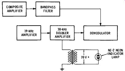
Fig. 4-57, Stereo multiplex indicator light (no oscillator circuit).
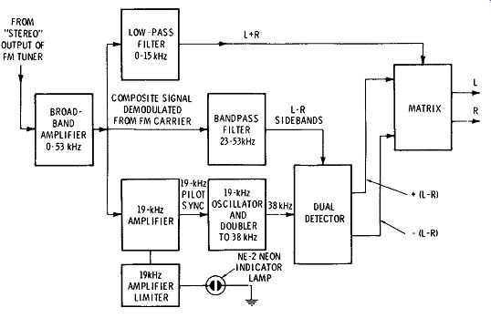
Fig. 4-58, Stereo multiplex with indicator-light takeoff before oscillator,
Automatic FM/FM Stereo Switching
Some higher-priced fm multiplex receivers have automatic switching circuits which operate to change the receiving mode when fm broadcast material changes from mono to stereo, and vice versa.
Fig. 4-61 shows a method of accomplishing this objective and at the same time providing for a stereo beacon light. This circuit is dependent on the 19-kHz pilot signal, and it operates with the age circuits of the receiver as shown.
Tuner Sensitivity and Noise Figure
It is a primary requirement that the tuner be able to bring in the desired stations clearly and without noise. The ability of a receiver to do this is related to its sensitivity. A sensitivity of 10 microvolts on fm reception or 75 microvolts on a-m reception will give good results for receivers operating within 15 miles of the broadcast station. For more distance, look for proportionately more sensitivity.
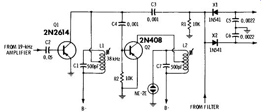
Fig. 4-59. Stereo indicator circuit in Knight Model KN-265.
If you live over 50 miles from the desired station, you should obtain the best tuner available with (probably) less than 3 microvolts sensitivity on fm reception and 10 microvolts on a-m reception. At greater distances, a-m stations will probably be the more reliable source of reception, and your choice of equipment should be so governed.
One of the most important characteristics of a low-level amplifier circuit is its signal-to-noise ratio. The input circuit of an amplifier inherently contains some thermal noise contributed by the resistive elements in the input device. All resistors generate a predictable quantity of noise power as a result of thermal activity. This power is about 160 dB below one watt for a bandwidth of 10 kHz.
When an input signal is amplified, the thermal noise generated in the input circuit is also amplified. If the ratio of signal power to noise power ( s / n) is the same in the output circuit as in the input circuit, the amplifier is considered to be "noiseless," and is said to have a noise figure of unity, or zero dB.
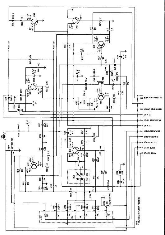
Fig. 4-60. Scott transistor multiplex circuit with indicator output.
In practical circuits, however, the ratio of signal power to noise power is inevitably impaired during amplification as a result of the generation of additional noise in the circuit elements. A measure of the degree of impairment is called the noise figure ( nf) of the amplifier, and is expressed as the ratio of signal power to noise power at the input (si/n1 ) divided by the ratio of signal power to noise power at the output ( s0 / n0 ), as follows:
nf = si/n1
So/Do
The noise figure in dB is equal to ten times the logarithm of this power ratio. For example, an amplifier with a one-dB noise figure decreases the signal-to-noise ratio by a factor of 1.26; for a 3-dB
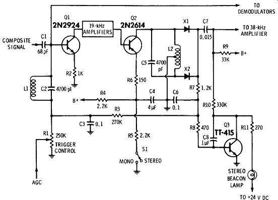
Fig. 4-61. Fisher Model 1249 beacon and automatic stereo circuit.
noise figure, the decrease is by a factor of 2; for a 10-dB noise figure, the decrease is by a factor of 10; and for a 20-dB noise figure, the decrease is by a factor of 100.
High-Performance Tuner
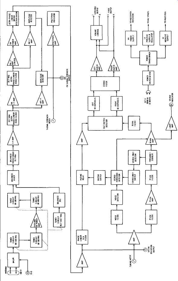
Fig. 4-62. Block diagram of McIntosh MR 73 tuner.
The McIntosh MR 73 am/ fm tuner ( shown in Fig. 4-51B) is a precision instrument with many interesting features. A functional block diagram of this tuner is shown in Fig. 4-62.
FM Radio-Frequency Section--The fm rf section contains the complete fm rf front end and part of the a-m rf circuits. A special four-section variable tuning capacitor provides rf selectivity and spurious-response rejection.
The two-stage, parallel-fed cascode rf amplifier gives better sensitivity and higher gain than conventional one-stage amplifiers. The use of junction field-effect transistors (JFET's) in this amplifier helps further to reduce the problem of front-end overload in strong signal areas.
The mixer, which also uses a JFET, is designed for high sensitivity and freedom from overload. Low-temperature-coefficient components are used in the fm local oscillator to prevent frequency drift. The rate of drift of the local oscillator is less than ten parts per million per degree centigrade, and this stability makes automatic frequency control ( afc) unnecessary.
Both the fm and a-m front ends have been designed in the same completely encased metal modules. This design gives protection against radiation or interference.
Antenna connections are provided for either 300-ohm twin lead or 75-ohm coaxial cable. The normal input impedance of the first rf amplifier is 75 ohms. Impedance match to 300 ohms is provided by a balun transformer which has negligible losses. Connections for a 300-ohm line are made with push-type terminals; no tools are required. A Type F male connector is furnished for 75-ohm coaxial cable.
For greater signal transfer and lower distortion, a special matching transformer has been designed to couple the fm rf section to the fm i-f amplifier. This matching transformer considerably enhances the linear phase characteristics of the i-f amplifier.
Fm i-f and Detector Section--The fm i-f consists of two integrated circuits and two phase-linear crystal filters. They combine to give a total gain of over 120 dB ( the signal is amplified to over 1,000,000 times its original level). The response curve has a nearly flat top with linear phase characteristics. The skirts of the response curve are very steep. The maximum width is 240 kHz at -3.0 dB and 400 kHz at -60 dB. The response curve is symmetrical each side of the center frequency. The crystal filters are permanently sealed and do not require adjusting. The i-f cannot drift nor vibrate out of adjustment. Each of the two integrated circuits contains 16 transistors, 3 zener diodes, 5 diodes, and 23 resistors, all on a single monolithic silicon chip.
A "phase" or "Foster-Seeley" discriminator has been designed to complement the integrated-circuit i-f section. The i-f section has high gain with hard limiting characteristics. It develops a capture ratio that is very low. The detected output signal of the discriminator is low in distortion content. De-emphasis of the discriminator output restores the frequency-amplitude characteristics that existed before transmission.
Stereo Multiplex Section--The multiplex section incorporates a special detecting circuit. A particular advantage of this circuit is the elimination of the critical adjustments necessary with commonly used matrixing circuits. The circuit detects the L - R sidebands, then automatically matrixes the recovered information with the L + R main-carrier signal. This yields the left and right program outputs with maximum separation.
The 19-kHz pilot signal is filtered from the composite stereo input signal, amplified by a special limiting amplifier, doubled to the 38-kHz carrier frequency, and then amplified again by a limiting amplifier. The composite signal minus the 19-kHz pilot is combined with the 38-kHz carrier signal. The new combination of signals is fed to the special detector circuit mentioned above. Balanced full-wave detectors are used to cancel the 38-kHz components in the output.
The SCA (Subsidiary Communication Authorization) signal must be removed from the composite output. This is accomplished by the use of a computer-designed "image parameter" band-elimination filter. The filter rejects SCA signals without impairing stereo performance. In the MR 73, fm muting operates by detecting ultrasonic noise which is present between stations or when a weak station is being received. The muting circuit can be activated or defeated by the use of the muting switch on the front panel. The level of muting desired can be adjusted by the muting level control on the top panel.
Varying the muting control adjusts the threshold at which the muting takes effect.
When the 19-kHz carrier of a stereo signal is received, the automatic fm stereo switching circuit activates the multiplex decoding circuit. This lights the stereo indicator. The circuit switching is all done electronically with no clicks. The automatic stereo switching can be defeated by turning the mode selector switch to fm mono. ( In this position, the stereo indicator will still light to indicate the presence of a stereo signal.) On monophonic transmissions, the stereo switching is inactive at all times, assuring a greater signal to-noise ratio. The stereo switching circuit has been designed so that noise will not activate it.
A-M Section--The a-m section uses MOS field-effect transistors.
The a-m rf amplifier circuit includes a three-section variable tuning capacitor in the metal-enclosed shielded module that also houses the fm rf front end. The a-m rf amplifier uses a dual-insulated-gate MOSFET to obtain more overload protection against strong local stations than can be obtained with conventional bipolar transistors.
The a-m mixer is also a dual-insulated-gate MOSFET. The use of MOSFET's in the rf amplifier and mixer stages makes possible low cross modulation ( spurious response) and good image rejection.
Three double-tuned i-f transformers are used to obtain selectivity while still allowing good a-m fidelity. A 10-kHz whistle filter has been incorporated at the output of the a-m detector. Its purpose is to suppress whistles that result from heterodyning between adjacent a-m carriers.
An external a-m antenna may be connected at the rear apron of the unit by using a push connector. An internal transformer matches the external antenna to the input impedance of the a-m front end.
An optional ferrite-core antenna is also provided for local or strong stations. A switch on the back panel selects either this antenna or the external antenna.
An a-m sensitivity switch is provided to decrease both the gain of the rf amplifier and the noise between stations.
Audio Preamplifier Section--The audio amplifier increases the level of the program so that it is adequate to drive a preamplifier or other accessory equipment. There is a three-transistor amplifier for each channel. The design uses considerable negative feedback to help achieve low distortion, wide frequency response, and excel lent stability. Each audio amplifier delivers 2.5 volts to the FIXED OUTPUT jacks at 600 ohms impedance. A second pair of outputs, the level at which can be varied by the volume control, is available.
The stereo filter is connected in the audio amplifier to reduce noise when a weak stereo station is being received. This filter is designed to permit a good compromise between channel separation and noise rejection.
Power Supply--All signal stages are powered from a 16-volt regulated supply. The 16-volt regulator is elaborate in design, using a specially selected transistor and associated circuit. The regulator uses electronic filtering to maintain a low background hum level, good stability, and good regulation.
A half-wave rectifier and filter supply the dc high voltage needed for the anode of the multipath indicator. A full-wave rectifier supplies dc to the multiplex indicator and to the voltage regulator.
TAPE RECORDERS
Tape recorders consist of tape-transport devices, motors, erase bias head, recording head, playback head, amplifiers, and controls.
Most lower-priced models combine the recording and playback operations in one head, requiring one less unit. The tape is generally transported from a reel through the erase, recording, and playback heads, drawn by a capstan and pressure roller driven by a constant speed motor.
The tape is finally wound on a second reel, usually operated by a separate motor ( see Fig. 4-63). As the tape is pulled through the recording or playback head, variations in flux density in the gap surrounding the tape are produced both in recording and playback.
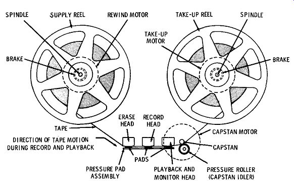
Fig. 4-63. Major parts of a tape-transport mechanism.
During recording, the signal to be recorded is fed to the recording head, causing a changing flux field which magnetizes the particles in the tape. On playback, the flux from the moving magnetized
particles in the tape induces a signal voltage in the playback head; this voltage is proportional to the residual magnetism of the particles at any point, and therefore is a reproduction of the recorded signal.
The problem of producing a linear recording on magnetic material is similar to that of producing linear output from a class-A amplifier.
The magnetization (hysteresis) curve shown in Fig. 4-64 has a changing slope with only a portion straight enough to use for hi-fi ...
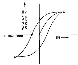
Fig. 4-64. Tape magnetization response.
... reproduction. The residual curve shows the relative magnetization left after the medium (tape) has left the magnetizing field. Just as in the operation of a class-A amplifier, only the straight portion of the curve can be used for hi-fi. Thus, the recording must be limited to the straight portion of the residual magnetization curve. This is accomplished by use of bias to change the relative operating level of the recording signal fed to the recording head. This may be done by application of dc or ac (supersonic) bias with the signal to the recording head.
When dc bias is used, a sufficiently positive dc field is applied just ahead of the recording head to magnetically saturate the tape medium. Then negative de bias is fed with the signal to the recording head. This negative bias is made sufficient to center the average recording level in the straight portion of the magnetization curve, as shown around point F in Fig. 4-64.
Supersonic ( ac) bias instead of dc bias may be applied with the signal directly to the recording head. The supersonic signal is above the audible range, in the neighborhood of 40 to 100 kHz-the higher the frequency, the more fidelity is possible.
The mixing effect of the signal to be recorded and the supersonic bias signal is shown in Fig. 4-65. The total signal variation is within the area of linear operation of curve AB, as described. The super sonic bias signal is recorded and reproduced along with the audio signal but cannot be heard by the human hearing system. The supersonic bias arrangement is very popular because it has quieter effects at low volume and silent areas of the program, and it is easy to produce and adjust.
Erase
Demagnetization principles, which have been used in other fields for years, are applied in a precise manner to erase a recorded signal from a tape. By applying an ac field to a tape in sufficient strength to produce complete magnetic saturation of all articles on the tape, thereby homogenizing its magnetic pattern, and then gradually decreasing the same ac field to zero strength, the tape will become demagnetized. For tape recorders, the ac field is obtained from the supersonic bias supply. In addition to the conveniences of this source for such a purpose, the possibility of a beat note from a separate supply is eliminated.
RECORDING SIGNAL ; LINEAR PORTION OF CURVE
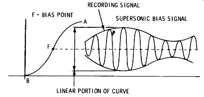
Fig. 4-65. Mixing and applying recording and bias signals.
Erasure may be applied in several ways. When a tape is recorded on, it is customary to erase continuously all information and noise just prior to the recording operation, as is provided for in tape recorders ( see position of erase head in Fig. 4-63). This removes any former programs or noises that may have been on the tape. Bulk erasing may be applied to the whole tape all at once. The same principle is used, but the tape is immersed in an ac magnetic field large enough to receive the reel. Bulk erase equipment is more powerful than recorder erase units and is used to erase more quickly and to restore tapes overloaded to near a permanent magnetization condition beyond the erase power of ordinary recorder equipment.
Tape-Drive Motors
Tape-drive motors must have properties similar to those of the very best motors used for phono turntables. Tape drives, however, do not have the advantage of the flywheel effect of a turntable to damp flutter and other changes of speed of the motor; therefore, perfection of motor design is even more desirable for tape. The best tape machines use hysteresis motors, which increase the cost of the machine considerably. For quality reproduction, motor flutter should have a rating of not higher than 0.5 percent, which is the audible level. For high-fidelity operation, the motor should be able to hold all variations in speed to less than 0.5 percent, and the better units are rated at less than 0.2 percent.
The total number of motors in a recorder may vary from one to three. The better machines usually have three-one for feed and re wind, one for take-up, and one for capstan drive.
Heads
The better machines provide three heads, as has been described: one each for erase, record, and playback. Optimum operation re quires a separate playback head not only to play back but also to monitor the signal as it is being recorded. This provides a simultaneous check on every link in the recording chain so that if any thing is wrong, ones does not have to do the recording over or lose the program. The erase, record, and playback heads are similarly constructed. However, separate design of heads is desirable because optimum operation of each requires different gap spacing and inductance characteristics. Heads contain a ring-shaped, high permeability core with a fine gap formed to allow a ¼-inch wide by 0.002-inch thick tape to pass with minimum clearance. The core has a winding to provide or pick up signals. Tape contacts the core at the gap either to be magnetized or to induce a field, according to the operation desired. Low-cost commercial tape-recorder heads provide reasonable recording and reproduction at voice frequencies, but most professional units require better heads. Hi-fi heads, such as Dynamu heads, are available to replace standard heads on lower- cost units. These can record and play back with full response± 3 dB up to 14,000 Hz, if the rest of the elements of the recorder are suitable.
Mechanical Features of Recorders
The transport mechanisms and controls of tape machines can be very elaborate. A tape-transport mechanism draws the tape past the heads at a constant rate of speed, that is, the speed at which the tape is to be played back. The tape is unwound from a reel, passed through the heads, and wound onto a take-up reel. A capstan with a roller device to press the tape against it pulls the tape at a constant speed. This may be reviewed in Fig. 4-63.
The feed reel has a torque applied in a direction opposite to the tape travel. The take-up reel has a similar torque in the direction of the tape travel to relieve the capstan of any difficulty in pulling the tape. On rewind, the pressure on the tape is freed to release it from the capstan, and the feed reel is reversed in direction and speeded up to rewind at high speed.
Miscellaneous
In the better equipment, brakes are usually provided to stop the reels quickly; various speeds are provided for rewind; interlocks are provided to protect tapes from fast rewind speeds during record or playback; electrical cutouts are provided to prevent erase during rewind or playback; release of tape pressure from heads during rewind is arranged to reduce wear; pressure is released on the capstan roller when not in use to prevent a flat spot on the rubber idler wheel; and automatic protection switches operate if the tape breaks or tangles.
Tape decks as separate machines or complete with amplifiers are available. Most equipment can be operated as a separate unit with an outside amplifier feeding the recording head, or the playback head feeding a separate audio system.
Audio amplifiers and controls to feed a recorder of the constant current type must provide from one-tenth to several milliamperes output. To provide for constant-current output, the output circuit must contain a majority of the impedance of the total coupling net work. The amplifier should also contain equalization networks to compensate for the magnetic recording characteristics. This equalization is built in most recorders, but if separate audio systems are used, similar compensation must be used. Compensation for recorders varies for different machines, but essentially each system only has to be arranged to equalize in playback the emphasis and de-emphasis applied to record any tape. Generally, a recording amplifier is compensated to NAB tape-recording standards, and regular preamplifiers ( for reproduction) with NAB tape-standard equalization are used.
Recording
Better stereo amplifier and control-center combinations have pro visions for two-channel output for stereophonic ( or monophonic) tape recording. These outputs can be fed directly to stereo tape recorders, and live stereo programs can be recorded for permanent storage.
This material can be obtained from actual two-microphone pickup (live) or live stereo broadcasts, or from stereo records. The program material may be fed from a tuner or a record player to the amplifier control center, monitored, balanced, emphasized or de-emphasized according to personal taste, and fed to the stereo tape recorder.
These tapes provide an optimum medium for permanent storage.
Prerecorded tapes are also available and have advantages over hi-fi records. An important advantage is permanence of fidelity. The quality of program material applied to prerecorded tape is practically permanent. With normal caution, prerecorded tape will not acquire surface noise over hundreds of plays. There is constant retention of frequency range and stereo effects in its program material.
Records do not have these characteristics. Discs always develop surf ace noise from needle wear and handling. Lint, dust, and scratches on records also contribute other undesirable noises and loss of quality and stereo effect on records.
The disadvantage of higher cost per unit playing time of pre-recorded tapes is being gradually overcome by reduction of speed in relation to fidelity of response. Cassette tapes with suitable characteristics and equipment operated at 1¼ inches per second can provide high-fidelity output at a price per minute competitive with standard LP records.
Playback
Many other recent improvements in techniques and equipment for tape recording and playback have made tape more competitive with discs as a home playback method. Other relative advantages and disadvantages of tape for playback were discussed in Section 3.
There are virtually no tape recording machines that are not also useful for tape playback. Thus a tape machine offers the advantage of allowing one to make his own recordings as well as to take advantage of permanent playback characteristics of high-quality prerecorded stereo tapes.
However, just "any old tape machine" is not enough to ensure stereo reproduction that satisfies the audiophile. The machine must be of better-than-average quality with respect to frequency response, freedom from flutter and wow, low harmonic distortion, and high signal-to-noise ratio.
All good stereo machines are now designed for "four-track" operation. As explained in Section 3, this means that two-channel stereo sound can be recorded on the full tape length in both directions.
The four-track arrangement requires special heads, mounted in a single head assembly over which the four-track tape passes.
Most tape-machine manufacturers sell both complete recording and playback systems and separate tape transports. A tape transport is the mechanical assembly of drive motors, drive system, and heads and bias-generating equipment to derive a signal from or record a signal on the tape. It does not include the equalizing networks, amplifier( s), and speaker( s) that come with a complete recorder playback unit. The transport can be used to play a stereo tape, with the outputs of the two playback heads fed to the inputs of the pre amplifier of a stereo high-fidelity system. Just about all preamplifiers include a position on the input equalizer switch for tape playback.
However, for recording with your tape transport, a separate amplifier may be necessary.
Typical high-quality tape machines for stereo recording and re production are illustrated in Figs. 4-66A through 4-66Q. Most machines operate at either of two speeds, with the speed selectable by the operator. A few operate at either 15 inches per second ( ips) or 7½ ips, others at either 7½ ips or 3¾ ips. Still others include a third speed, 1 7/8 ips; cassette machines operate at this speed exclusively.
It is an inherent property of the tape method of recording for frequency response to improve with increasing speed, and a check of manufacturers' specifications will show this. However, it must be re membered that as speed increases, playing time for a given length of tape decreases. Also, a two-track stereo tape which plays back only in one direction provides only half the playing time of a four-track, two-channel tape. Table 4-1 shows various characteristics of tape for several different modes of operation.
Claims as to frequency response at a given speed vary from one machine and manufacturer to another. It should be noted whether the response is claimed with a variation of 2 dB, 3 dB, or just on some "usable response." Machines using a speed of 15 ips obtain better response with less technical difficulty at that speed than machines using lower speeds. Response at 15 ips should be from about 30 or 40 Hz to 20,000 Hz or more with variation in the order of plus or minus 2 dB. The upper limit of response ( ± 2 dB) at 7½ ips is usually about 12,000 to 18,000 Hz, and at 3¾ ips between 7500 and 12,000 Hz. New designs operating at 1 7/8 ips are providing comparatively excellent frequency response. Do not let a few hundred hertz of upper-limit frequency response be a final criterion in your choice of a machine, because manufacturers differ in the rigidity and manner of making their tests. Listening is the best test.
Total-harmonic-distortion tolerances are about the same as those for amplifier equipment alone, and about 2 percent should be considered maximum.
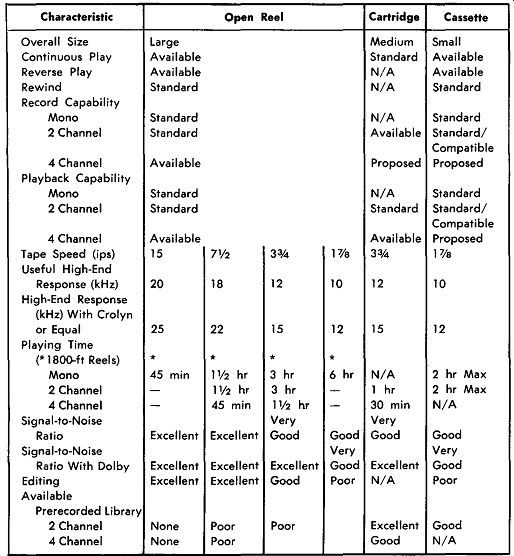
Table 4-1. Comparison of Tape-Format
Characteristics for stereo recording and reproduction.
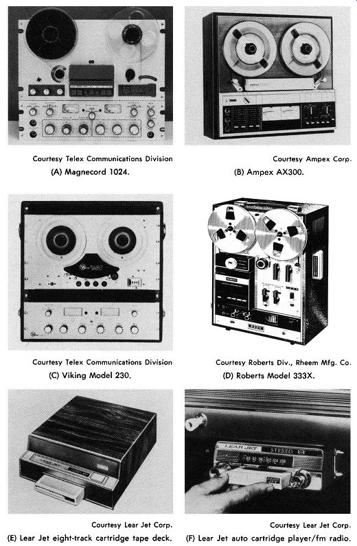
-------- Fig. 4-66. Typical tape machines
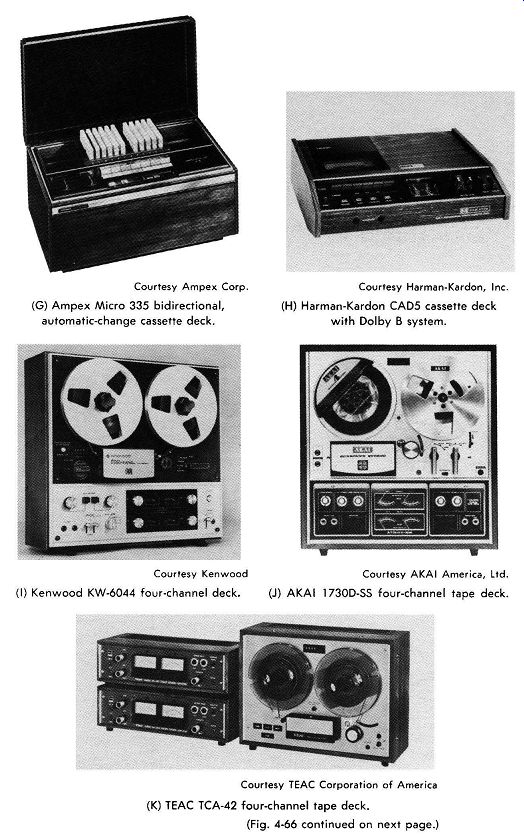
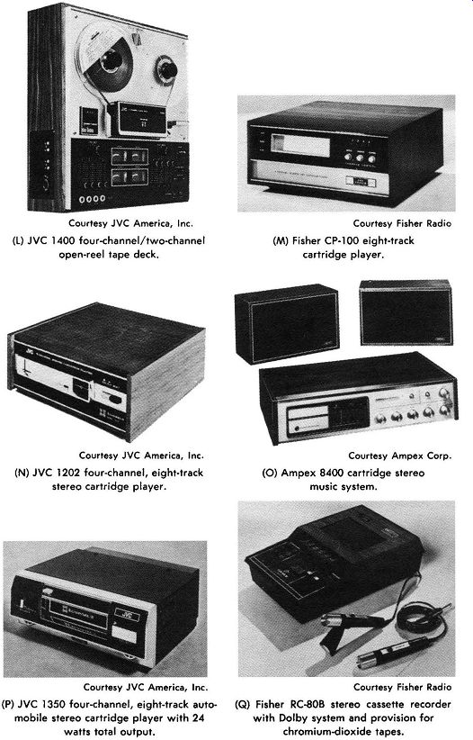
Typical tape machines for stereo recording and reproduction.-(cont.)
Courtesy Telex Communications Division (A) Magnecord 1024.
Courtesy Telex Communications Division (C) Viking Model 230. Courtesy Lear Jet Corp.
(E) Lear Jet eight-track cartridge tape deck.
Courtesy Ampex Corp.
(B) Ampex AX300. Courtesy Roberts Div., Rheem Mfg. Co.
(D) Roberts Model 333X. Courtesy Lear Jet Corp.
(F) Lear Jet auto cartridge player /fm radio.
Courtesy Ampex Corp.
(G) Ampex Micro 335 bidirectional, automatic-change cassette deck.
Courtesy Kenwood (I) Kenwood KW-6044 four-channel deck.
Courtesy Harman-Kardon, Inc.
(H) Harman-Kardon CAD5 cassette deck with Dolby B system.
Courtesy AKAi America, Ltd.
(J) AKAi 1730D-SS four-channel tape deck.
Courtesy TEAC Corporation of America (K) TEAC TCA-42 four-channel tape deck.
Courtesy JVC America, Inc . (L) JVC 1400 four-channel/two-channel open-reel tape deck.
Courtesy JVC America, Inc . (N) JVC 1202 four-channel, eight-track stereo cartridge player.
Courtesy JVC America, Inc . (P) JVC 1350 four-channel, eight-track auto mobile stereo cartridge player with 24 watts total output.
Courtesy Fisher Radio (M) Fisher CP-100 eight-track cartridge player.
Courtesy Ampex Corp.
(0) Ampex 8400 cartridge stereo music system.
Courtesy Fisher Radio (Q) Fisher RC-808 stereo cassette recorder with Dolby system and provision for chromium-dioxide tapes.
Signal-to-noise ratio is important in tape machines because a relatively high noise level is one of the basic problems tape-machine manufacturers have had to overcome. A minimum signal-to-noise ratio acceptable to the high-fidelity enthusiast is at least 40 dB, and 50 or 60 dB is considered highly desirable.
As explained in Section 3, one of the disadvantages of tape machines has been the inconvenience of having to thread the head assembly and set up the reels properly. For this reason, cartridge type tape-machine arrangements have been developed. The cart ridge is loaded with standard ¼-inch tape and plays up to an hour of stereo at 3¾ ips. Threading of the tape is not necessary because the tape is already "set up" in the cartridge. The cartridge is merely inserted or removed as desired.
The machine in Fig. 66D accommodates reels, cartridges, and cassettes.
Figs. 4-66E and 4-66F show the Lear Jet 8 eight-track stereo cartridge players, which have a comparatively flat response at frequencies up to 10 kHz. As shown, a model with fm radio included is available for the car, and another model is available as a tape deck for the home. The car model operates on 12 volts dc, and the home model operates on 115 volts ac. These units accept cartridges which can play continuously, with one hour of program material which will repeat until turned off. The tape deck may be indexed ( advanced) to any one of four portions of the program material by depressing a button on the panel.
Two-channel cassette stereo recorders are shown in Figs. 4-66G, 4-66H, and 4-66Q. Stereo cassettes come with a range of playing periods including 30, 60, 90, and 120 minutes ( total time for both directions). The cassette operates with a tape speed of 1 7/8 ips, but with quality equipment and the latest techniques, recording and reproduction with excellent response characteristics up to 12,000 Hz can be achieved.
Figs. 4-66-I, 4-66J, and 4-66K show four-channel open-reel recorders which can record two channels and/ or play back two or four discrete channels. The Kenwood tape deck shown in Fig. 4-66-I has four independent preamplifiers and special provision for selection of correct bias for low-noise, high-density tapes ( Crolyn, cobalt, etc.) to provide optimum quality of reproduction from 20 Hz to 20 kHz with a signal-to-noise ratio better than 47 dB ( before application of Dolby). This unit also offers three tape speeds-7½, 3¾, and 1% ips-easy rewind, VU meters for four channels, two microphone inputs, two line inputs, and four line outputs, plus headphone jack, four-digit counter, and automatic shutoff.
Fig. 4-66L shows the JVC four-channel/two-channel open-reel stereo tape deck that can record or play back all four discrete channels, as well as two channels on four-track tape. This recorder has specifications that include frequency response of 20 to 25,000 Hz and signal-to-noise ratio of 53 dB. Figs. 4-66M, 4-66N, 4-660, and 4-66P show four-channel, eight track cartridge-tape decks. The players shown have frequency response ratings of 30 to 12,000 and 15,000 Hz, depending on tape type and associated equipment.
The four-channel, eight-track cartridge player shown in Fig. 4-66P is designed for use in an automobile. This circuit is compatible for playing two-channel cartridges. There is provided fine correction of channel separation, L-R balance control, front-rear balance control, and a program indicator.
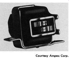
Fig. 4-67. Ampex bidirectional head for cassette decks. Courtesy Ampex
Corp.
The Ampex bidirectional deep-gap cassette head shown in Fig. 4-67 ( used in the recorder shown in Fig. 4-66G) combines six separate elements in a single unit to provide bidirectional erase/ play/ record capability in full two-channel stereo. With all elements in one head, alignment problems are reduced, and recordings made in either direction have identical characteristics. This head has deep-gap design, which is said to improve quality.
For more information on tape formats and capabilities, see Section 3.
The Dolby Noise-Reduction System
To enhance the output quality of the slow-speed, narrow-track cassette, the Harmon Kardon CAD5 professional tape deck shown in Fig. 4-66H has incorporated the licensed Dolby B system.
Dolby has developed a sophisticated system for recording and playback of tapes that provides a 10 to 15 dB improvement in signal-to-noise ratio. The original system was designed for master tapes to be used for making prerecorded production tapes and discs, but the system has been modified and applied to recording and playback of prerecorded reels, cassettes, and cartridges for home use.
The Dolby system is a two-step, symmetrical process that operates before and after recording. Whenever the strength of certain components of lower-level signals being fed to a recorder falls below a predetermined threshold, the system boosts their strength before recording. The signal is then recorded in this encoded form, and during the recording process, the customary noise is added by the electronic circuits of the recorder and by the operation of the mechanical equipment on the tape itself. During playback, the mirror image of the same Dolby process that boosted these signal components before recording returns them to the original level. At the same time, the noise added during the recording process is reduced. The effective reduction in hiss level is approximately 10 dB. The original system (Dolby A) operates by dividing the audio band into segments as follows:
1. Below 80 Hz
2. 80 to 3000 Hz
3. 3000 to 9000 Hz
4. 9000 Hz and up
Each segment is processed separately. All signals which are of sufficient strength, say 40 dB over the noise level, to provide good performance pass straight through the Dolby system without change.
Signals of lesser magnitude are emphasized 10 to 15 dB. The output from the Dolbyized recording therefore contains almost exclusively signals at least 40 dB above the noise level.
Courtesy Advent Corp.
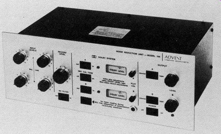
Fig. 4-68. Advent Model 100 noise-reduction unit.
To reproduce, the Dolby system processes the boosted signals back to their initial relative level and at the same time reduces the noise by the same amount, leaving the signals unaltered in recording still unaltered in playback. The output is therefore a low-noise reproduction without disturbances such as hum, hiss, cross talk, and other unwanted distortion. The Dolby system provides a 10- to 25 percent improvement in signal-to-noise ratio.
A somewhat simplified system--sometimes called the Dolby B system--has been developed for home use. The B system provides 3 dB of noise reduction at 600 Hz, 8 dB at 2 kHz, and 10 dB at 4 kHz.
The type B system works only on the lower-level signals, in the same manner as the A system previously described, but over less of the audio spectrum. This system was designed primarily to eliminate tape hiss.
(A) Operations on signal. (B) Characteristic curves.
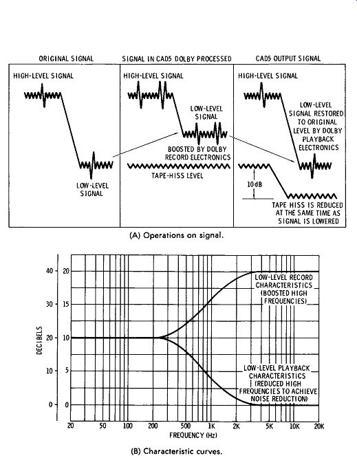
Fig. 4-69. Dolby B processing in Harman-Kardon CADS tape deck.
Fig. 4-68 shows a noise-reduction unit that is a simultaneous record-playback control center incorporating the Dolby audio noise reduction system. It consists of two separate sections, a complete Dolby record preamplifier and playback Dolby circuits. Among the functions offered by the unit illustrated are the following:
1. Separate input-level controls on both stereo channels for both microphone and line inputs. These maintain input mixing capabilities for any recorder, and add these capabilities to recorders presently lacking them.
2. A master recording-level control that governs both stereo channels and allows the recording level to be set without disturbing the balance of stereo channels or individual inputs.
3. Output-level controls for each channel that permit matching the requirements of any preamplifier, amplifier, or receiver.
4. A multiplex-filter switch that prevents recording interference from inadequate suppression of multiplex-carrier or pilot-tone frequencies by a tuner.
5. Complete calibration facilities for optimum use of the Dolby system with any recorder. These include two calibration meters, an internal test-tone oscillator, and "Dolby level" tapes ( open reel and cassette) that make it possible to set the unit to a standard characteristic for all Dolbyized tapes, including pre recorded commercial releases.
6. A headphone output.
7. Source-tape monitor switches.
Fig. 4-69 shows graphically how the Dolby system works. In Fig. 4-69A, the original signal is fed into the Dolby record circuit of the CADS tape deck (shown in Fig. 4-66H). High-level signals are unchanged, but low-level signals are boosted before recording.
Since tape hiss is added to the boosted signal, the hiss is reduced at the same time the boosted signal is brought back to normal by the Dolby playback circuit. The top curve of Fig. 4-69B shows the boosting characteristic of the Dolby record circuit at extremely low signal levels. If the signal level is higher, the boosting is cut back in a precise way. The bottom curve shows the complementary, mirror-image characteristic of the Dolby playback circuit. The play-back circuit compensates exactly for the record circuit, resulting in overall flat frequency response and excellent transient performance under all signal conditions.
When the Dolby system is coupled with the new chromium dioxide tapes, the improvement in performance is even greater because of added frequency response.
It is important to note that the Dolby B cassette deck shown can be used for recording and reproducing either using or not using Dolby processing. If a prerecorded tape has been Dolbyized, the instrument switch is operated in the Dolby position; if the tape is not Dolbyized, the switch should be off. However, excellent results have been obtained from listening to prerecorded Dolbyized tapes on ordinary cassette recorders.
Other Noise-Reduction Systems
The Dolby system is intended for use before and after recording without removing any noise already in the material before recording.
There are available other units, however, that can filter noise at any stage of the processing. One system has a dynamic filter system to attenuate noise from any source by as much as 10 to 20 dB. This system uses broad-band notch-type suppression which is varied by the level of the incoming signal in the frequency range covered by the notch.
At normal program levels, the system does not operate. When the signal level within the notch lowers to 25 to 50 dB below normal, the filter attenuates the high frequencies. The attenuation increases as the notch-frequency signal level falls. This reduces the noise level 10 dB or more.
Another available system provides compression-expansion capabilities in a similar manner to the emphasis-de-emphasis techniques used in record equalization, except that the dynamic range is adjustable and is greater. This system is designed to operate in any low-impedance, low-power-level line between two units, such as between a preamplifier and power amplifier or between a tape deck and preamplifier.
MICROPHONES
Many types of microphones are available. Each has certain ad vantages and disadvantages. The type of material to be reproduced, the placement of the microphone, whether it is to be used indoors or outdoors, the frequency response desired, and a number of other factors affect the choice of a microphone.
The basic types of microphones, grouped according to their principle of operation, are:
1. Carbon
2. Crystal
3. Dynamic
4. Ribbon
5. Capacitor
Each of these microphone types has its own characteristics with respect to output level, frequency response, output impedance, and directivity. These characteristics determine whether or not a micro phone is suitable for a given application.
Output Level
The output level of a microphone is important because it governs the amount of amplification that must be available for use with the microphone. The output level of microphones is usually given in dB preceded by a minus sign. The minus sign means that the output level is so many dB below the reference level of 1 milliwatt for a specified sound pressure.
The unit of sound pressure used in rating microphones is referred to as a bar. A bar is equal to a sound pressure of 1 dyne per square centimeter. Speech provides sound pressures between 0.4 and 15 bars. For music, the pressure ranges from 0.5 to 1250 bars.
Microphones are rated in a number of different ways, and this often causes confusion. If ratings are given in any manner other than in bars, it is a good idea to convert the output level rating to dB below 1 milliwatt for a sound pressure of 1 bar. Table 4-2 gives correction factors which, when applied to the corresponding method of microphone rating, will convert it to output level in dB below 1 milliwatt for a sound pressure of 1 bar. When a rating has been converted to these terms, it is much simpler to use when calculating amplifier gain requirements and the like.
A microphone with a low output level necessitates the use of an amplifier with greater gain, which, in turn, increases the possibility of noise and hum. The absolute minimum noise level which can be practically attained at the grid of the input tube of an amplifier is about -125 dB. From this, it has been determined that to have a reasonably quiet installation, the microphone level should not be below -85 dB. When very low-level microphones are used, it is often necessary to provide a direct-current heater supply for the input tube, in order to eliminate hum which results when an ac heater supply is used.

Table 4-2. Comparison of Microphone Ratings
Frequency Response
The frequency response of a microphone is a rating of the fidelity of relative output voltage which results from sound waves of different frequencies. The simplest way to find a complete picture of the frequency-response characteristics of a microphone is to plot a curve of its output voltage versus input frequency. Since good modern microphones are relatively flat over their range, it is often considered sufficient to specify the range over which their output does not vary more than plus or minus 1 or 2 dB. For ordinary home high-fidelity use, a microphone frequency response curve should be reasonably flat between 40 and 10,000 Hz.
With systems designed specifically for speech reinforcement, a lower limit of 150 Hz and an upper limit of 5000 Hz are entirely satisfactory. Where it is desired to reproduce music with the highest possible fidelity, the frequency response should be flat ( within 2 dB) from about 40 to 15,000 Hz. Fig. 4-70 shows the response of several types of microphones.
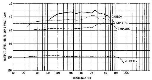
Fig. 4-70. Frequency-response curves for typical microphones.
Output Impedance
The output impedance of a dynamic or velocity microphone re quires a transformer or network to match the input impedance of the amplifier. Higher-impedance microphones, such as the crystal types, require only a simple network. Microphones generally employed in public-address systems have impedances of from 20 to 500,000 ohms.
Directivity
Microphones do not respond equally to sounds reaching them from all angles. Their frequency-response characteristics also vary, depending on the angle at which the sound reaches them. A microphone may respond equally to all frequencies between 40 and 10,000 Hz when the sound is originating directly in front of it, while the high-frequency response falls off rapidly as the sound originates farther to either side. Where it is necessary to pick up sound from all directions, the directional characteristics of some microphones are not suitable. Fig. 4-71 shows examples of the four important directivity characteristics which can be obtained with the various types of microphones.
CARDIOID NONDIRECTIONAL SEMI-DIRECTIONAL BIDIRECTIONAL

Fig. 4-71. Microphone polar response patterns.
The directional characteristics of a microphone can be used to accomplish a number of things. Noise pickup can be reduced by choosing and placing the microphone so that it will not respond to sound originating at the point where the noise is produced. Feed back, which can be very troublesome, can often be completely eliminated by the careful choice and placement of a microphone.
Carbon Microphones
When the maximum output level is required from a microphone, the carbon microphone is often used. While it does have the ad vantage of high output, the frequency response characteristics of the carbon microphone are poor, and it cannot be used for hi-fi work.
The carbon microphone consists essentially of a diaphragm and a small cup filled with carbon granules. Fig. 4-72 shows the construction of a typical carbon microphone.
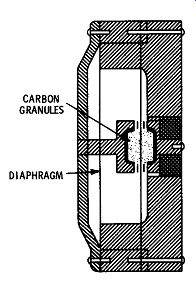
Fig, 4-72. Construction of a carbon microphone.
CARBON ; GRANUIIS DIAPHRAGM
A carbon microphone generates a continuous hiss. This hiss is due to small variations in contact resistance which take place between the carbon granules.
The average output level of carbon microphones is of the order of -30 dB. The best carbon microphones have a frequency response of approximately 60 to 7000 Hz. They are substantially non-directional, although their high-frequency response above 300 Hz usually falls off at angles exceeding 40 degrees from the front of the micro phone. Although carbon microphones are not used for high-fidelity work, their ruggedness, low cost, and high output make them useful in a few cases.
Crystal Microphones
The crystal microphone is the type most widely used in lower cost installations. The crystal microphone has a relatively high out put level and a high impedance. The impedance of the crystal microphone is high enough that it can be connected through a short cable directly to the grid circuit of a basic amplifier, eliminating the need for an input transformer and preamplifier. A long cable will reduce the output voltage available from a crystal microphone and may effect its high-frequency response.
The most commonly encountered type of crystal microphone employs a diaphragm which moves in accordance with sound waves striking it and exerts pressure on the crystal ( Fig. 4-73) . This type of construction permits complete enclosure of the crystal and reduces the effects of humidity.
The output level of this type of microphone is usually between -48 and -60 dB. The output impedance is almost always more than 100,000 ohms.
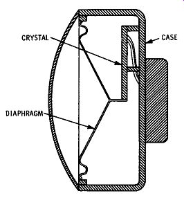
Fig. 4-73. Construction of a crystal microphone.
The crystal microphone is normally nondirectional, although a special pressure-gradient crystal microphone which gives a unidirectional response pattern is now being marketed. This microphone gives excellent results.
Good units may have a frequency response substantially flat be tween 50 and 10,000 Hz. Units are available with slightly wider frequency-response ranges.
Rochelle-salt crystal microphones should not be used in locations where the humidity is extremely high. They should never be subjected to high temperatures. If such a crystal microphone is subjected to a temperature of 130 degrees, it will be rendered completely useless. Care must always be taken to avoid exposing a crystal microphone to direct sunlight for any length of time.
Dynamic Microphones
The dynamic microphone consists of a metal diaphragm, a coil which is connected to it, and a magnet ( Fig. 4-7 4). In construction and operation, this type of microphone is similar to a dynamic speaker. When sound waves strike the diaphragm, the coil moves.
Since the coil is in the field of the permanent magnet, there is induced in the coil a current which is directly proportional to the sound waves striking the diaphragm. This current constitutes the output of the microphone. Dynamic microphones are available with limited or wide-range frequency-response characteristics.
The natural output impedance of a dynamic microphone is be tween 30 and 50 ohms. Very often, a transformer is incorporated in the microphone, raising its output impedance to a value between 200 and 25,000 ohms. The average dynamic microphone is simple and sturdy. It is not affected by atmospheric changes, has a long life, and is well adapted to all-around hi-fi work.
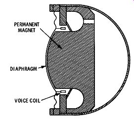
Fig. 4-74. Construction of a dynamic microphone.
PERMANENT MAGNET; DIAPHRAGM; VOICE COIL
The output level of most dynamic microphones is about 55 or more dB below 1 milliwatt per bar. The ordinary dynamic micro-phone is essentially nondirectional, although its high-frequency response falls off rapidly on either side, as shown in Fig. 4-75. To make full use of the frequency range of a dynamic microphone, the microphone should face directly toward the source of sound. A special type of dynamic microphone is available for use when high ...
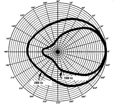
Fig. 4-75. Directivity of a dynamic microphone.
... background noise levels are encountered. The response of these units falls off rapidly as the distance between the microphone and the source of the sound increases.
Velocity Microphones
The velocity ( or ribbon) microphone consists of a very thin ribbon of aluminum foil suspended in the field of a powerful permanent magnet, as shown in Fig. 4-76. The ribbon is corrugated and can move quite freely. The ribbon moves in accordance with the velocity of the sound wave. Response is proportional to the difference in sound pressure between the two sides of the ribbon.
The natural impedance of the ribbon element is about ¼ ohm.
A transformer is usually mounted within the microphone case, stepping up the impedance at the microphone terminals to a value between 25 and 35,000 ohms. For public-address use, the high impedance units are convenient since they can be connected directly to the grid of an input tube.
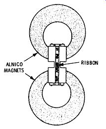
Fig. 4-76. Construction of a velocity microphone.
The output level of velocity microphones is usually 60 dB below 1 milliwatt per bar. Generally, velocity microphones have excellent response characteristics.
The velocity microphone is bidirectional. Maximum response is to sound reaching the front or back of the microphone at a 90-degree angle to the plane of the ribbon faces. This type of microphone is more directional than the crystal and dynamic microphones, and it has an overall response that falls off as the angle of the sound reaching it varies from 90 degrees to the faces of the ribbon (Fig. 4-77).
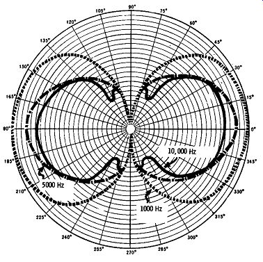
Fig. 4-77. Directivity of a velocity microphone.
The velocity microphone is quite sensitive to the movement of the air surrounding it, and it must be carefully protected from puffs of wind when used outdoors. A ribbon microphone should be at least 18 inches from the source of the sound.
Capacitor Microphones
The capacitor ( or condenser) microphone consists of a fixed plate and a diaphragm, as shown in Fig. 4-78. The diaphragm is actuated by the changing pressure of the sound waves striking it, causing the diaphragm to change its position in relation to the fixed plate. This results in a change in the capacitance between the diaphragm and the plate, which is utilized to produce a corresponding voltage drop across a resistor connected in series with the microphone and a charging source.
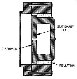
Fig. 4-78. Construction of a capacitor microphone.
The output level of the capacitor microphone is extremely low, and a high-gain amplifier must be used with it. The amplifier should be mounted directly at the microphone, usually right in the micro phone case. The capacitor microphone has excellent frequency response and low distortion. Because of the necessity of mounting an amplifier at or in the microphone case, this type of microphone is not recommended for ordinary hi-fi work.
Combination Microphones
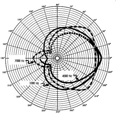
Fig. 4-79. Directivity of a dual-unit microphone.
Microphones are available which make use of two units to secure a particular directional pattern. A dynamic unit is often combined with a velocity ( or ribbon) unit. Fig. 4-79 shows the directional pattern which results when a bidirectional velocity unit and a non directional dynamic unit are combined. The resultant directivity pattern is known as a cardioid, since it is heart-shaped. Other units are also combined to secure similar directivity patterns. Another type of combination microphone, designed especially for stereo recording, is pictured in Fig. 3-4.
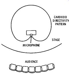
Fig. 4-80. Use of cardioid microphone.
Microphone Selection
Microphones should be carefully selected in order to utilize the electrical and physical characteristics of the various types, as de scribed previously. There are no particular rules which can be strictly adhered to in the selection of a microphone. There are, how ever, a few points which should be kept in mind.
A microphone should be selected with frequency-response characteristics equivalent to those of the other components in the system.
A Rochelle-salt crystal microphone should never be used where it is likely to be subjected to a temperature of more than 120 degrees.
Cardioid microphones should be used when "behind-the-mike" pickup must be eliminated. Fig. 4-80 shows the application of a cardioid microphone on a speaker's platform. The back of the microphone faces the audience. Since the microphone is not sensitive to sounds reaching it from this direction, no audience sounds will be picked up and amplified through the system.
In systems where a speaker must move about a great deal, the lapel microphone is very useful. A number of contact microphones are available for use with string instruments.
Many installations require the use of more than one microphone.
An example of this is illustrated in Fig. 4-81. Four microphones are used to pick up sound originating at three different points. Microphone A picks up sound from a soloist, microphone B picks up sound from a chorus, and microphones C and D pick up sound from an orchestra.
The microphones used have been chosen and placed so that they will pick up the designated sound only. In other words, the micro phone in front of the orchestra will pick up sound from the orchestra, but not from the chorus or the soloist. This makes it possible to control the pickup from the three elements-the orchestra, the chorus, and the soloist-individually, so that each may be given the proper degree of reinforcement. A microphone setup such as this is particularly useful in adjusting the level necessary for a vocalist, since a vocalist requires a greater degree of sound reinforcement than does an orchestra.
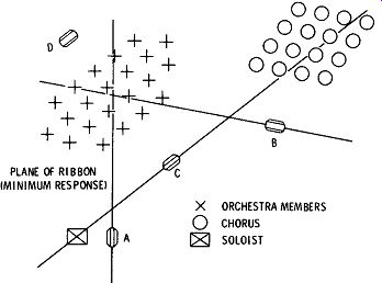
Fig. 4-81. Microphone placement plan.
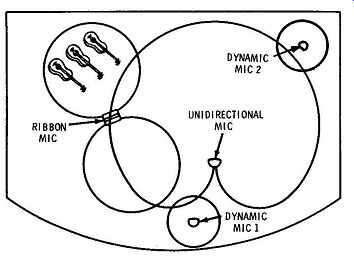
Fig. 4-82. Multiple-microphone installation.
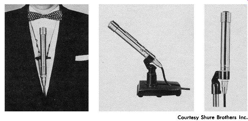
Fig. 4-83. Shure Model 535 dynamic microphone.
Fig. 4-82 shows another multiple microphone installation. Here, a cardioid microphone is used for overall pickup. It faces the orchestra so that the audience is in the dead area of the microphone.
A dynamic microphone is used for pickup from a master of ceremonies or vocalist. A third microphone, this one a velocity micro phone, is used to pick up sound from the violin section of the orchestra, and a fourth microphone is used to pick up background sound.
In addition to the differences in pickup patterns, microphone sizes and shapes also vary greatly. In selecting a microphone, consider what uses it will be put to, then select one with the response pattern that will fill the need. Many are quite versatile. For example, the unit pictured in Fig. 4-83 can be held in the hand, worn around the neck on a lavaliere cord and clip, or supported by a desk or floor stand.
TELEVISION
Another source of program to feed a hi-fi system is the audio signal accompanying each television picture signal. The audio equipment in the average television receiver is not of high-fidelity nature.
If one wishes, arrangements can be made to pick off the audio signal after detection from the television receiver and feed it through a hi-fi system. The pick-off point should be at a point as near the second detector as a proper impedance match will allow. The lead to the preamplifier should be short.
One can obtain a separate high-fidelity fm tuner for television stations. Such tuners have features similar to those of standard fm tuners, except that they cover the television frequencies only, and the channels are calibrated on the dial.