The amplifier/preamplifier section of a hi-fi system includes circuits and components necessary to provide power output, inversion, voltage amplification, preamplification, compensation, and a full set of operating controls.
Most commercially available amplifiers and preamplifiers for high-fidelity performance are designed for stereo, rather than mono phonic operation. This actually means that they can be used for either. However, because there will always be some monophonic amplifiers and because a stereo system is really a coordinated multiple monophonic system with some modifications, we shall discuss these sections first as applied to monophonic form. Then, the methods of combining and modifying for stereo will be given, with examples of actual units.
Preamplifiers are required to bring the level of low- and medium level signals up sufficiently to provide a useful input to amplifier units. But their most distinctive function is to provide frequency response equalization and controls for volume, loudness, balance, phase, and bass and treble emphasis or de-emphasis. In other words, the modem preamplifier is also an "audio control center." However, some special-purpose preamplifiers, such as those for amplification and equalization of the outputs of variable-reluctance cartridges, do not have controls.
The suitability of an amplifier for an installation depends on a number of factors, the most important being its power output, gain, input impedances, output impedances, frequency response, distortions, controls, and the characteristics of the power supply from which it operates. The requirements of the installation and limitations of other components should be considered before the amplifier is chosen. These factors and requirements will be discussed in Section 8, on systems design, selection, and installation.
Basic amplifiers are units with power output stages, inverters, and limited voltage amplification only. Preamplifiers are necessary to increase medium- and low-level input signals, such as those from reluctance phono pickups and velocity or dynamic microphones, to the minimum input level required for full output of the basic amplifier. Preamplifier-equalizers raise the signal and provide for record equalization.
Audio control centers including preamplifiers, equalizing net works, boost, droop, loudness, compensation, filtering, decoding, and switching circuits are more elaborate and usually are used instead of the plain preamplifier or a simple preamplifier-equalizer. Lower and medium-cost amplifiers are available which provide in the same unit for all functions just described. However, it is to be expected that the overall quality will have a relation to the price.
The power amplifier unit or section provides amplification and power to actuate the speaker. Average hi-fi speakers for average living rooms require at least 10 watts of audio output power per channel from the amplifier, to handle most conditions. When several rooms, large rooms, or outside areas are to be supplied with the highest fidelity, 60 to 200 watts of power might be desirable in a home installation. This audio output power is provided by the basic amplifier unit or by the amplifier section of a preamplifier and power-amplifier combination unit.
According to the need, from 50 to 100 dB of amplification of very low-level signals from pickups and other inputs, plus compensation and controls to obtain various emphasis, is provided by the pre amplifier-equalizer part of the system or by a separate hi-fi control center unit.
Hi-fi systems may be designed around either of these two types of amplifier arrangements, that is, the combination of preamplifier, control, and power amplifier, all in one unit such as shown in Figs. 5-1A and 5-1B, or the control center plus basic amplifier units used separately, as shown in Figs. 5-2A and 5-2B. In addition, there are complete compacts ( see Fig. 5-7 4). Circuit arrangements and components may be somewhat similar in both arrangements, but more flexibility and better results can be expected from separate units. It is easier to provide optimum design for separate units, due to differences in conditions of control, amplification, power, vibration, shielding, regulation, and noise problems in each of the separate units, such as the tuner, preamplifier, and the basic amplifier. However, it is a matter of practical system design when a tuner is to be used to decide whether the operating controls are more desirable on the tuner panel, in a separate preamp control panel, or on the amplifier unit itself. The answer to this will depend on the system requirements, the location conditions, and the user's preference.
(A) Heathkit Model AA-15 stereo amplifier. Courtesy Heath Co. (B) AKAi Model AA-6100 four-channel amplifier. Courtesy AKAi America, Ltd.
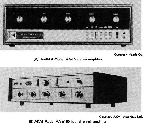
Fig. 5-1. Stereo master audio controls. Courtesy McIntosh Laboratory Inc.
(A) McIntosh C-26 preamplifier. Courtesy Harman-Kardon, Inc. (B) Harman-Kardon
Citation Twelve amplifier.
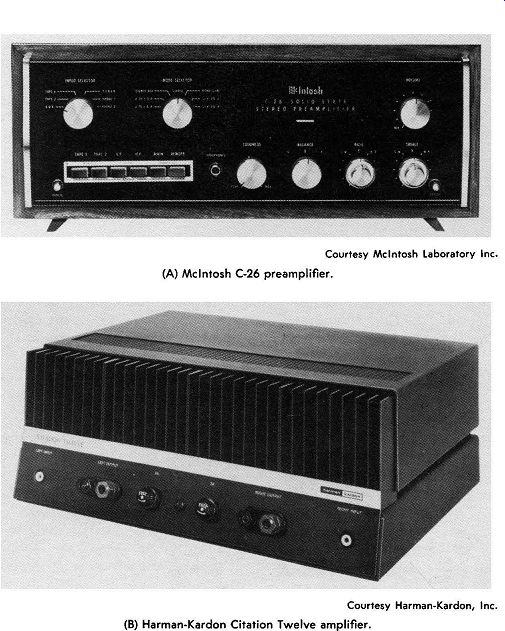
Fig. 5-2. Separate stereo amplifiers.
The preamplifier and control section ( either as a separate unit or as part of a complete amplifier unit) may provide controls for power on and off, switching the various possible inputs or combinations of inputs into the system, volume, record equalization or compensation, bass and treble boost or droop, filtering, and loudness. This section should also provide amplification of the very lowest input signals to be used to a level sufficient to drive the power-amplifier section to full output.
Record equalization is provided to compensate for pre-emphasis and de-emphasis applied to records in their manufacturing process.
Records are made with all high audio frequencies heavily pre emphasized; i.e., the recorded volume of the highs is proportionately much higher than the normally recorded mid-range frequencies, for the purpose of reducing noise during playback. On playback, the emphasized signal overrides or masks the undesirable random noise and needle-scratch noises in the high audio-frequency spectrum.
When the recording is made, the volume level of the high frequencies above 1000 Hz ( RIAA, AES, NAB, ORTHO) is increased as shown by the curve in Fig. 5-3. When the record is played back, the preamplifier can be adjusted to proportionately de-emphasize these signals in an equal but opposite manner, as shown by the curve in Fig. 5-4, developing an audio output very close to the original recorder input.
The same technique is used in fm broadcasting and accounts for much of the superiority of frequency modulation over amplitude modulation when proper compensation is applied in the reproducing amplifier.
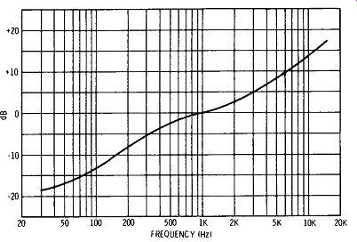
Fig. 5-3. RIAA recording curve.
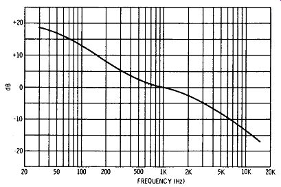
Fig. 5-4. RIAA playback curve.
In a similar but opposite manner, the very low frequencies are de-emphasized as shown in Fig. 5-3. This is done to compensate for the wide swings of the record cutter caused by the very low notes. Such wide cuts in the record groove must be reduced, or the grooves would have to be made with more spacing, causing a reduction of possible recorded time. Large movements of the stylus also introduce uncontrollable distortions in the recording head.
Emphasis in playback must be provided to compensate for this deemphasis on the records. Fig. 5-4 shows how this is provided for.
Loudness controls are provided to compensate for the normal variation in response linearity of the ear at different volume levels.
It was described in Section 1, Fig. 1-1, that as the volume (intensity) of sound is reduced, reality supposedly becomes more distant because the sensitivity of the human ear to highs and lows drops off from the response to the "midrange" frequencies.
The loudness control provides circuits to emphasize the low and high ends of the audio spectrum for the purpose of bringing reality closer as reproduction volume is proportionately reduced. Some amplifiers have multiple ganged controls to provide for automatic loudness compensation as volume is varied. Other equipment em ploys switching circuits to provide one or more values of emphasis.
Bass and treble controls provide control of emphasis and deemphasis similar to that provided by the equalization controls, but in a variable manner so that they can be adjusted according to individual taste. These controls, one for treble and one for bass notes, are usually adjustable to provide plus or minus 15 or 20 dB variation of either the highs or lows at the ends of the audio spectrum. Advanced equipment provides for rolloff frequency adjustment with constant attenuation slopes and special filters for disturbances such as turntable rumble and objectionable high frequencies.
A balance control provides adjustment of the relative volume output of each of two channels of a stereo amplifier. A phase switch provides for reversal of the input of one of two stereo channels with respect to the other. This is used to correct the phasing of outputs of pickup cartridges and fm multiplex outputs, and to correct differences in amplifier output phase if two power amplifiers of different design are used.
There are other controls that may be included for three- or four speaker stereo. These will be discussed later.
How the preamplifier and control sections function will be described in detail following an explanation of the basic power amplifier and its important components.
POWER AMPLIFIERS
Power amplifiers utilize vacuum tubes or transistors to develop the required power to drive the speakers. Vacuum tubes are essentially high-impedance input and output devices. Since speakers are low impedance devices, a means of transforming the power from the high-impedance output of vacuum tubes to the low impedance of the speaker is necessary. The device normally used is a transformer, which must be of high quality, or all the care of amplification in a quality manner up to this point in the circuit is lost.
Transistors, on the other hand, have low-impedance characteristics at both the input and the output, and circuits have been devised to direct-couple transistor power amplifiers to speakers without an output transformer. In many cases the output circuits can be designed to match closely a fixed-ohmage load within the output load range that will provide uniform output with extremely low distortion. However, there are applications of transistor audio circuits in which transformers are the best means of matching because of variable load conditions that cannot be directly matched properly with transistors.
The most costly and major limiting design factor in power amplifiers is the output transformer. The output transformer is considered to be the most important part of the amplifier, and because of its close relationship to the speaker system, we will consider it first. It is one of the most critical components in the high-fidelity system.
Modem resistance-coupled amplifier design is such that excellent frequency response and low distortion are inexpensively obtained in the low-level stages preceding the output stage. But at the relatively high power level of the output circuit there are more chances for distortion, and failure to use a high-fidelity type of transformer can nullify all the advantages developed in the careful design of the preceding portions of the amplifier.
In the selection of an amplifier, an amplifier kit, or a circuit for construction, consideration and investigation of the quality of the output transformer is of primary importance. Also, high-fidelity enthusiasts frequently replace output transformers and experiment with their characteristics. Such experimenting often leads to substantial improvement in performance and often allows response adjustments to suit individual tastes. Although the design and construction of these components must of course be left to specialists, the high-fidelity enthusiast will have a keen interest in the factors which make the output transformer so critical and cause its cost to represent a large proportion of his high-fidelity budget. For this reason, the following brief review of the factors most important in the selection of output transformers is included.
Symbolically, and in its basic principle, the output transformer is the same as any transformer designed to couple power to a load from a source. However, unlike ordinary power transformers, output transformers must maintain a high degree of efficiency over a range of frequencies, rather than just at the power frequency, and they must not distort the original signal waveform.
The effects of various factors in the transformer on performance can be most easily visualized in reference to an equivalent circuit, illustrated along with the actual circuit in Fig. 5-5. The equivalent circuit, being in the form of a simple series-parallel connection of inductors and resistors, allows analysis of the effects of any one factor. This equivalent circuit is not complete, because there are also effects from distributed capacitances of the windings, capacitance between windings, and capacitances to ground. Because the output transformer is heavily loaded (low impedance), the capacitances can be neglected unless the design is very poor. The equivalent circuit is made up of two main parts: ( 1) the primary portion, including effects derived from the primary circuit, and ( 2) the reflected portion, corresponding to effects reflected from the secondary into the primary. Any impedance so coupled is "transformed" to a new
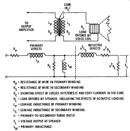
Fig. 5-5. Actual and equivalent circuits of an output transformer.
value by the turns ratio; the impedance transformation ratio is the square of the turns ratio. This is why the reflected inductance and resistance from the secondary are each multiplied by n2. Winding Resistances Rp and Rs As shown by the equivalent circuit, these resistances act in series with the source, adding to its internal impedance. The higher the resistances, the greater is the voltage drop across them at high cur rents ( high output power), and thus the poorer the voltage regulation. Since current through a resistance dissipates power, these resistances represent a power loss in the transformer, reducing its efficiency. The ill effects of excessive resistance dictate that wire as large as possible, consistent with size, weight, and coupling co efficient, be used.
Leakage Inductances I,, and L,.
Leakage inductances also act in series with the source. The reactance they offer to impede the signal depends on frequency, being equal to 2 pi fL. At low frequencies the leakage reactances are negligible, but at high frequencies they must be minimized; otherwise they interfere with frequency response. Leakage inductance is the inductive effect resulting from the flux of one winding which does not link with the other winding. In good high-fidelity transformers, leakage reactances are minimized by careful attention to the physical shape, mounting, and orientation of the windings on the core.
In some cases, the primary and secondary windings are interwound; that is, a few turns of the primary are wound, then a few turns of the secondary, then some more of the primary, and so on. This is obviously an expensive procedure, and it is one of the reasons for the relatively high cost of a good output transformer.
Core Losses
There are two types of core losses. Eddy currents are electric currents generated in the core material due to the fact that it simulates a conductor being cut by lines of magnetic force. The core material has appreciable resistance and thus dissipates power wasted in heating the core. It is because of eddy currents that cores are made of many laminations ( thin sheets) instead of solid metal. The flux threading through the core is thereby divided into a small portion for each lamination; this, plus the fact that the resistance of the core is increased by the laminations, greatly reduces eddy current losses as compared with those in solid material. The thinner the laminations ( maintaining the same total volume of material), the lower are the eddy current losses, but also the more expensive is the construction. The other kind of core loss is that due to hysteresis. This is the tendency of the core material to retain residual magnetism and thus resist the positive and negative flux alternations necessary for transformer action. Hysteresis is a function of core material. Much research has been done on determining and developing high-grade core materials. Core laminations employed in output transformers for high-fidelity use are of carefully selected materials with minimum hysteresis loss and of as high resistivity as possible to minimize eddy currents.
Both eddy currents and hysteresis losses have the same effect on transformer performance as would be produced by the connection of a shunt resistor across the input to the transformer, as illustrated by R., in Fig. 5-5. The greater the core losses, the lower is the equivalent resistance of Re and, therefore, the greater is its shunting effect.
Primary Inductance
Before a transformer can operate properly, magnetic flux must be set up in the core and be maintained there. This is the job of the primary inductance. It is the inductive reactance which limits no load current to a reasonable value. If primary inductance is too low, it shunts the input signal. Since inductive reactance is proportional to frequency ( XL = 2 pi fL), its shunting effect is worst at low frequencies, being one of the limiting factors for low-frequency response.
Practical Performance Factors in the Output Transformer
The preceding discussion covers the important factors involved in the performance of the output transformer in general. For high fidelity we are interested in how these factors affect performance in practical, commercially available types. Such effects can be made clearer by redrawing the equivalent circuit twice, once including only those factors important at high audio frequencies and once for factors important at low audio frequencies. Such equivalent circuits are shown in Fig. 5-6. In transformers of reasonably good quality, core losses become negligible, so they are not shown here. Also, as previously mentioned, distributed and other capacitances, important in the high-impedance interstage transformer, are negligible here because of the relatively low impedance involved.
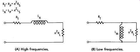
(A) High frequencies. (B) Low frequencies.
Fig. 5-6. Effective equivalent circuits at high and low frequencies.
In Fig. 5-6A, it can be seen that the combined leakage reactances form the important high-frequency factor. If equivalent combined leakage inductance LA becomes excessive, most of the input voltage at high frequencies appears across it, rather than across the load.
At the same time, a large LA causes phase shift and phase distortion of the output signal. The closer the coupling coefficient between the primary and secondary is to unity, the lower is the leakage inductance. Manufacturers of high-fidelity transformers employ special methods of interwinding the turns to minimize leakage inductance.
In Fig. 5-6B, it is apparent that the important low-frequency factor is the primary inductance, LM. It was not included in the high-frequency circuit of Fig. 5-6A because its reactance is so high at high frequencies that it appears as an open circuit. At some low frequency, however, the reactance of LM becomes low enough to cause an important shunting effect across the reflected load. This means a loss of low frequencies and a phase shift at low frequencies.
For this reason, manufacturers of high-fidelity output transformers try to use as many turns as possible. But in doing so, they make it harder to avoid more leakage inductance, so a careful compromise between the two must be made. By careful use of interwinding and choice of physical dimensions and shapes, both of these factors are made much more favorable in high-fidelity transformers than in the run-of-the-mill types.
Choosing and Testing Output Transformers
The high-fidelity enthusiast who wishes to purchase an output transformer is faced with an array of commercially available units, ranging in cost from about a dollar to as much as one-hundred dollars or more. Tiny, cheap transformers made to a price for low cost radio receivers can be ruled out immediately, since they can hardly be considered as high-fidelity equipment. Also, all high fidelity systems worthy of the name use push-pull output; therefore, we will not consider single-ended transformers.
From here on, it depends on the person himself and the limits he has set on his system as a whole. The speaker system is of first consideration in this respect, since most amplifiers preceding the output transformer are so high in quality that they are not a factor. Using a high-grade output transformer with a relatively poor speaker system does not allow full realization of the capabilities of the trans former. A transformer with performance comparable to that of the speaker is cheaper and sounds no worse. On the other hand, if you intend to change to a speaker of better quality in the future, it is often wise to get the best possible transformer in the beginning, and thus eliminate the transformer as a serious limiting factor in later changes and tests.
If a top-notch transformer is in order, the purchaser is quite safe in buying one of two or three special types known by high-fidelity men everywhere. Companies such as those whose wide reputation rests primarily on such a unit produce a uniform and dependable product.
Few systems warrant the ultimate in transformer specifications, and few pocketbooks can stand making the whole system the best available. Among more moderately priced output transformers, manufacturers are not always definite about performance. For ex ample, sometimes the drop-off in response over the specified frequency range is not stated. If it is 2 dB or less, then the range means something. Examples of good and poor response curves are shown in Fig. 5-7. The curves actually show relative response with respect to response at 400 Hz. In other words, to compare only frequency response, and not total output, the response at 400 Hz ( and thus over the entire middle portion of the range) is plotted along the same line, even though output level under particular actual operating circumstances may be different. Note how much greater a frequency-response range could be claimed if the drop-off is taken at 5 dB or 10 dB.
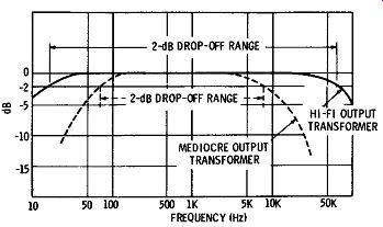
Fig. 5-7. Output-transformer response characteristics.
Some specifications do not take into account the tolerance in the balance between the two halves of the primary. If there is unbalance, distortion is introduced in proportion to the degree of unbalance. Also, unbalance will cause the magnetic flux from the two halves of the primary to fail to balance in the core; unbalance in the fluxes causes possible overload and core saturation, with magnetic overload distortion, hum, and overheating.
Because these things are not apparent in over-the-counter buying, the high-fidelity enthusiast may wish to be prepared to make certain basic tests on a transformer. For this purpose, the following checking and testing procedures are given:
1. Check the relative weight, Heavy transformers are not necessarily good ones, but good ones for high-fidelity performance are heavy. The low-frequency response depends on core volume. While it is true that the efficiency of core materials has been greatly improved of late, it still takes a husky chunk of iron to do a good job down to 50 Hz. If you have examined and handled top-notch trans-formers, you have developed an idea of what the weight must be and can make comparisons.
2. Try it in an amplifier. Listening is, of course, the ultimate functional test, providing conditions are so controlled that any distortion heard can be attributed to the transformer. However, testing equipment is required to make other than an aural test. To make laboratory-type tests, you should know the characteristics of the amplifier used, because such things as unbalance in the output tubes or other inherent amplifier imperfections can introduce distortion which might mistakenly be blamed on the transformer. If these characteristics of the amplifier are known, then you can temporarily hook the transformer into it and make tests as shown in Fig. 5-8.
Run tests on amplitude distortion and frequency response. These tests check for unbalance and other deficiencies automatically.
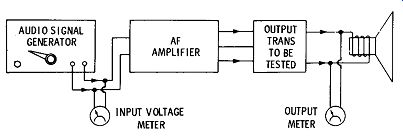
Fig. 5-8. Setup for output-transformer tests.
3. More advanced tests with an impedance bridge. It is not always handy to install the prospective transformer in an amplifier, or perhaps you are building your first amplifier and do not have a standard amplifier, but you still want to buy and check your trans former before installation. In this case, there are a few tests which, though far from a complete analysis, give a good idea of whether you are buying a well-designed component. These tests call for an impedance bridge. The method of testing is illustrated in Fig. 5-9.
It is as follows:
(A) First check for unbalance, because if there is too much un balance the transformer is unsuitable and further tests are not necessary. Unbalance is checked as shown in Fig. 5-9A. The resistance and inductance of each half of the primary winding, with the secondary winding open, are measured. The percentage difference between them is the percentage of unbalance. Unbalance of 1 percent is considered low enough to be good, 5 percent is only fair, and more is poor.
(B) Now check the total primary inductance, as illustrated in Fig. 5-9B. The reason this test is appropriate will probably be more clear on re-examination of Fig. 5-5. If, in this equivalent circuit, the load is removed (to simulate an open secondary), it can be seen that the only inductances in the circuit are the leakage inductance of the primary and the primary inductance. The leakage inductance, even in relatively poor transformers, is very much less than the primary inductance, and it is therefore negligible in this test. Thus, the measurement of the inductance across the primary leads with the secondary open is a reasonable check on primary inductance. How ever, because the bridge measurement is at low signal level, it makes no check on the inductance at high audio levels. How the inductance holds up under increases of signal amplitude depends on the adequacy of the core. If the weight, volume, and material of the core are sufficient, the bridge measurement of inductance should be a good indication of primary inductance. The minimum acceptable value is about 15 henrys; the method of interpreting the measurement is explained in the following paragraphs.
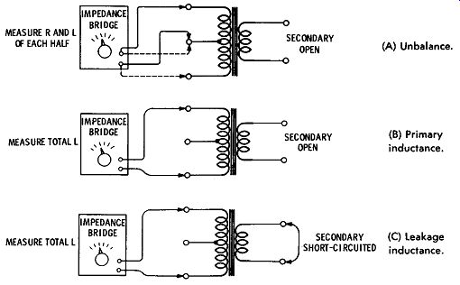
(A) Unbalance. SECONDARY (B) Primary OPEN inductance. SECONDARY (C) leakage SHORT-CIRCUITED inductance.
Fig. 5-9. Simple tests on output transformers.
( C) Check leakage inductance. This is done by short-circuiting the secondary winding and again measuring the inductance across the total primary winding, as illustrated in Fig. 5-9C. By reference to Fig. 5-5, it can be seen that short-circuiting the load shunts the primary inductance with the relatively low value n2 L8, so effectively there is just the leakage inductance in the circuit. Now our bridge measurement indicates a relatively low value. Maximum leakage inductance allowable in a good transformer is of the order of about 75 millihenrys.
Frequency response is usually stated in terms of the range between the frequencies at which the output falls off 3 dB. These limiting frequencies are: ( 1) that low frequency at which the primary inductance has a reactance equal to the load impedance ( the load impedance is that offered to the output tubes for proper operation and is listed as such in the tube manuals), and ( 2) that high frequency at which the leakage reactance becomes equal to the load impedance. For example, if the load impedance is 6000 ohms, a primary inductance of at least 19 henrys is required to reach 50 Hz at low frequency drop-off ( XL = 2 pi j L = 6.28 X 50 X 19 = 5970 ohms). For the same impedance, 95 millihenrys leakage inductance would allow ...
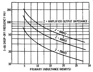
Fig. 5-10. Primary inductance required versus minimum response frequency.
... response to 10,000 Hz, whereas 63 millihenrys allows response to 15,000 Hz. For the convenience of the reader, graphs showing lower and upper response limitations, respectively, for typical values of load resistance and a range of inductances are included in Figs. 5-10 and 5-11.
It must again be emphasized that the foregoing relations hold only if the inductances are correct for at least normal operating levels. This is where the power rating of the transformer becomes important. For instance, if a transformer is rated at 5 watts, and is to be operated at 10 watts, distortion is likely to result because the core is overloaded. The core will saturate, and the peaks of the audio waveform will be flattened, as illustrated in Fig. 5-12. It is good policy to operate well below the power rating of the transformer to allow for good dynamic range in the system. In other words, al though normal operating average power may be about 5 watts in a typical case, the peak power on momentary loud passages may go to several times that.
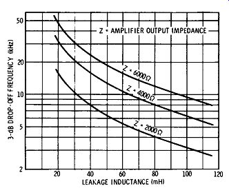
Fig. 5-11. Maximum leakage inductance versus highest response frequency.
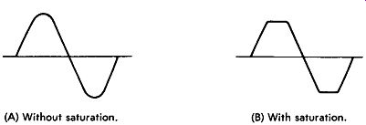
(A) Without saturation. (B) With saturation.
Fig. 5-12. Waveform of a transformer in which the core is saturating.
Output Impedance
The output impedance of an amplifier should equal the input impedance of the speaker system to be driven. For universal application, it is desirable to choose an amplifier having a transformer with a range of output impedances including one to match a 500- or 600 ohm line. This facility is useful when it is desired to operate a speaker at some distance from the amplifier, as considerable loss is experienced in long lines unless a matched-impedance feed line of 250 ohms or more is used. If a 500-ohm line impedance is used, it is necessary to use a 300- to 500-ohm transmission line feeding a 500 ohm output-impedance transformer to the speaker. This transformer should be placed at the speaker and should have outputs matching the speaker system. This transformer should be equal in overall quality to the output transformer. Standard impedance output values desirable are: 4, 8, 16, 32, and 500 ohms.
Characteristics of Tube Versus Transistor Power Amplifiers
The ability of an amplifier to deliver its rated power into a speaker load depends on the impedance match between the two. The advent of solid-state amplifiers, which usually do not use multiple-impedance output transformers, requires proper selection of speakers in regard to impedance.
Vacuum-tube amplifiers, because of the high impedance of the output tubes, require a transformer to match to the typical speaker, and it is easy to include several "taps" for matching speakers of different impedances. Transistor amplifiers, however, generally do not require an output transformer because the efficient matching impedance of a typical transistor output stage is some value between 4 and 16 ohms, close to the nominal impedance of most speakers.
A transistor amplifier has a single optimum load impedance deter mined by its circuit design, and therefore it is not able to deliver full power into a range of fixed load impedances, as is readily possible with a vacuum-tube amplifier.
Speakers are not fixed-impedance devices. The impedance of any speaker or speaker system varies over its useful frequency range.
The Electronic Industries Association specifies that the rated impedance shall be the minimum impedance over the useful frequency response of the speaker. However, even where the manufacturer adheres to this rating procedure, combinations of speakers in systems and the settings of crossover controls for mid-range and treble balance may significantly alter the impedance characteristics. The minimum (rated) impedance may rise to several times the rated value at other frequencies, usually reaching its low-end peak at the resonant frequency of the speaker enclosure system. Since speaker impedance is not purely resistive, other factors also limit speaker ability to utilize the amplifier rated power. Large multiple-speaker systems may appear as largely capacitive loads, just like a full-range electrostatic speaker, and the electrostatic speaker may drop well below its rated impedance at some frequencies.
Because the load is not a constant impedance, no amplifier can deliver equal power into any speaker system at all frequencies. Tube amplifiers with multiple-impedance output transformers can match several specific loads ( but not simultaneously), and an impedance mismatch has a similar power limitation on any amplifier, tube or transistor. The Institute of High Fidelity has chosen 8 ohms as the standard impedance for rating power amplifiers-the modal nominal impedance, but speakers vary from 4 to 32 ohms.
A transistor amplifier which delivers 60 watts maximum into an 8-ohm load delivers between 30 and 40 watts into a 16-ohm load, and less into a 32-ohm load. Lower load impedances, such as 4 ohms, cause more current in transistors than do higher impedances. Excessive current can lead to rapid transistor failure unless the power output is deliberately limited to prevent excessive current. There, care should be used in application, matching, and operating.
In order to minimize problems of excessive current, some solid state amplifiers require the use of series resistors with 4-ohm speakers to prevent damage. This soaks up a high percentage of the available power and greatly diminishes the effective damping of the speaker. The same problem exists with speakers ( supposedly specially designed for transistor amplifiers) which include series resistors in order to present a more nearly uniform impedance characteristic. Because the majority of 16-ohm speakers are more efficient than the most popular 4-ohm speakers, it is of greater importance to most users to have the best match between 4 and 8 ohms.
It is worth noting that direct-coupled transistor power amplifiers cannot be parallel to obtain higher power output at usable speaker impedances. Because these amplifiers are essentially current or constant-voltage amplifiers, when they are paralleled the same voltage will be available only at an output impedance which is too low for general speaker use, and there is risk of damage to the amplifier through interconnection of the two outputs. For higher-power applications, the preferred procedure is to drive each channel of the amplifier with identical signals, and connect each output to a separate speaker system.
Diffused silicon transistors permit good circuit performance at high frequencies. Silicon transistors are desirable for power output stages because of their ability to perform at much higher junction temperatures than can germanium transistors. This means smaller heat-radiating fins can be used for the same power dissipation. On the negative side, silicon often has higher saturation resistance, which gives decreased operating efficiency that becomes appreciable in operation from low-voltage supplies.
POWER AMPLIFIER CIRCUITS
Next to the output transformer and the speaker, the power amplifier circuit and the other components used therein are usually the most important factors governing the percentage of distortion present in a system. Since it is usually desired to keep distortion to the lowest value consistent with economy, the power amplifier should be carefully designed. Some form of degenerative feedback should always be used. Feedback reduces harmonic distortion, stabilizes the output impedance, and reduces the effects which resonance in speakers has on the output.
Push-pull arrangements will give a low percentage of distortion.
Triodes in push-pull give excellent results. The use of beam tubes in ordinary circuits results in distortion higher than is permissible unless sufficient degenerative feedback is used. From 15 to 20 dB of feedback should be used in beam-power amplifiers.
Beam-power tubes used in push-pull arrangements for higher than average power ( 100 watts or more per channel) in certain modem circuit designs give negligible distortion and are recommended when highest-quality reproduction and high output of music are desired.
Transistors are used in quasi-complementary-symmetry circuits which are essentially class-B circuits that provide outstanding performance for the most stringent requirements for high-fidelity systems. Silicon transistor arrangements can be used to supply 70 to 100 watts per channel with negligible distortion, high reliability, and comparatively low cost. In addition, these arrangements require a minimum of space and provide a maximum of weight reduction.
They can be direct-coupled to eliminate expensive, heavy, and bulky output transformers, and they have become the most widely used output device in equipment with power ratings under 100 watts per channel.
Output Circuits
Amplifiers in general are classed by letters, A, B, and C, according to the method of adjusting the tubes or transistors. Audio power output stages are generally adjusted for class A, class AB, or some times class B, but never for class C. Preamplifier stages are usually voltage amplifiers and are adjusted to operate in the class-A region.
A class-A amplifier circuit has a fixed bias, and the applied signals are so arranged that plate or collector current is present at all times.
A class-B amplifier is one in which the operating fixed bias is adjusted approximately to the cutoff value for the tube or transistor so that plate or collector current is quite low with no signal and so that there is plate or collector current for each half-cycle of an applied ac signal.
A class-AB amplifier is adjusted so that the fixed bias and applied alternating signal cause plate or collector current to be present for appreciably more than half but less than the entire signal cycle.
Class-C amplifiers are so arranged that plate or collector current is present for less than half of the signal cycle. Class-C circuit arrangements are not used in audio work.
Class-A and class-AB arrangements are well known for their high fidelity characteristics. In years past, circuits arranged to operate in class A were the only acceptable amplifier circuits for hi-fi equipment, but today the best amplifiers operate in class AB with special compromise arrangements (untra-linear and unity-coupling designs) to bring about audio reproduction with practically unmeasurable distortion and with excellent response and high outputs.
Class-A amplifiers are used for linear audio amplifier service at low power levels. When power amplifiers are used in this class of operation, the amplifier output usually is transformer-coupled to the load circuit, as in Fig. 5-13. At low power levels, the class-A amplifier can also be coupled to the load by resistor, capacitor, or direct coupling techniques.
There is some distortion in a class-A stage because of the non linearity of the active device and circuit components. The maximum efficiency is not realized. The class-A transistor amplifier is usually biased so that the quiescent collector current is midway between the maximum and minimum values of the output-current swing.
Collector current, therefore, is present at all times and imposes a constant drain on the power supply. This drain is a distinct disadvantage when higher power levels are required or operation from a battery is desired .
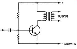
Fig. 5-13. Basic class-A transformer-coupled transistor amplifier.
Class-B and class-AB power amplifiers are usually used in pairs in a push-pull circuit because conduction is not maintained over the complete cycle. A circuit of this type is shown in Fig. 5-14. If conduction in each device occurs during approximately 180 degrees of a cycle and the driving wave is split in phase, the class-B stage can be used as a linear power amplifier. The maximum efficiency of the class-B stage at full power output can be as high as 78.5 per cent when two transistors are used. In a class-B amplifier, the maxi mum power dissipation is 0.203 times the maximum power output and occurs at 42 percent of the maximum output.
Standard single-ended parallel or push-pull parallel circuit arrangements do not produce sufficient fidelity to be used for hi-fi systems. Push-pull arrangements produce less distortion because even harmonics, plate-current effects in the transformer, and hum pickup in the plate circuit normally tend to cancel out.
There are several successful types of push-pull amplifiers in cur rent use in output circuits utilizing triode, tetrode, transistor, and ultralinear (hybrid) circuits. Pentode amplifiers have such nonlinear characteristics that they cannot be considered as high-fidelity equipment. Triode arrangements with triode-connected tetrodes ( Fig. 5-15) and silicon transistors offer the simplest approach to high fidelity.
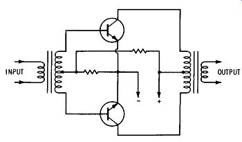
Fig. 5-14. Basic class-AB transistor amplifier.
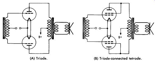
(A) Triode. (B) Triode-connected tetrode.
Fig. 5-15. Power-amplifier stages.
This approach may be used with or without additional overall systems circuit improvements such as negative feedback ( to be discussed later). Compared with straight tetrode-connected operation, transistor and triode-connected output stages using comparable components provide better stability, noncritical performance, less distortion, and better speaker-damping characteristics.
However, triode amplifiers ( compared with tetrodes) have the following disadvantages: ( 1) Triode amplifiers have the lowest efficiency; therefore they require large and more expensive components, tubes, and power supplies to obtain outputs equivalent to those obtained from tetrode amplifiers. ( 2) Triode amplifiers re quire much more driving power. This condition further increases cost. The overall percentage of distortion will be increased by each additional stage required to raise the power sufficiently to drive the triode amplifiers. The higher the power required from any intermediate stage, the higher the distortion of the output of that stage will be. All these distortions are added to the final triode amplifier stage distortion, partially negating the advantages to be gained in the use of the triode output stage itself.
Tube-type amplifiers presently are used mostly where power output requirements exceed 100 watts per channel. For power outputs under 100 watts per channel, transistors offer many advantages and, therefore, are most popular. The following discussions of amplifier theory apply to both tubes and transistors. In some cases, tubes and transistors are interchangeable in a circuit arrangement, provided that the components necessary to be matched in impedance and other characteristics are changed accordingly but the circuit principles do not change.
Tetrode Amplifier Circuits
The efficiency of a tetrode amplifier can be as high as 60 percent.
Tetrodes operated in certain circuits have very high amplification characteristics, requiring but a fraction of the drive of triode and transistor amplifiers. These advantages make possible the reduction of cost to a practical commercial level for manufacture of very high-power high-fidelity amplifier equipment. The disadvantages of tetrode amplifier design have been overcome by circuit, component, and electron-tube improvement to the extent that highly satisfactory results can be attained. Technically, the output characteristics of tetrode amplifiers have been so improved that the measurable distortion is negligible. A tetrode final amplifier circuit is shown in Fig. 5-16.
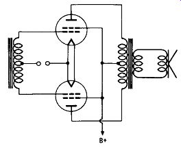
Fig. 5-16. Tetrode power amplifier.
Ultralinear operation involves a compromise circuit arrangement in which a tetrode is connected neither as a triode nor as a tetrode, but special taps on the primary of the output transformer are connected to the screens, thereby providing an amplifier operation having some of the advantages of both tetrode and triode operation.
At the same time, the disadvantages of both types of circuits are reduced. This circuit arrangement is more efficient and has more gain than straight triode operation, and at the same time the stability and speaker-damping characteristics are practically as good as in straight triode operation. Most important, distortion in the power output stage is hardly increased over that of triode operation. This compromise design is generally accepted as one of the better con temporary approaches to high-fidelity power-amplifier circuits. The circuit arrangement to achieve this is shown in Fig. 5-17. The tap point varies from 20 percent to 40 percent of the winding, with considerable difference of opinion between different manufacturers as to the optimum point. Tap-point design is usually determined empirically by listening tests. Always, when the human ear is involved, measurement by a fixed standard is impossible. Therefore, one must listen to each unit to determine which is preferable to him.
Another design considered optimum by current standards is the patented McIntosh unity-coupling circuit ( Fig. 5-18). "Unity coupling" is a name which identifies a group of audio amplifier circuits.
These circuits are designed to reduce distortion at high frequencies ( the treble range) which conventional push-pull circuits may generate.
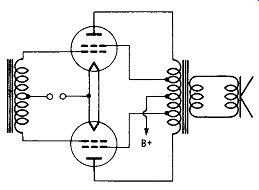
Fig. 5-17. Ultralinear power-amplifier circuit.
To illustrate this problem graphically, consider a tone waveshape as shown in Fig. 5-19A. One push-pull tube operates from A to B, the other from C to D. Both tubes operate from B to C. The small interval BC can be reduced to zero, though it seldom is practical to do so.
One half of a push-pull amplifier ideally produces a wave as shown in Fig. 5-19B. It consists of one-half a sine wave and a flat.
The half cycles from the two halves of the amplifier are added together to make the full wave in the output transformer.
The conventional transformer consists of two halves wound as shown in Fig. 5-19C. At high frequencies, the flat between successive half-waves changes shape. Graphically, the change appears as shown in Fig. 5-19D. The new shape from B to C is due to the collapse of the magnetic energy in the output transformer, which is not completely coupled from one half to the other. When two waves of this shape are added together, they appear as shown in Fig. 5-19E. The departure from the original tone shape represents the addition of new tones generated by the amplifier itself.
Courtesy McIntosh Laboratory Inc.
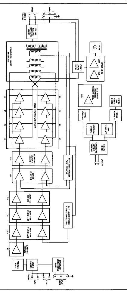
Fig. 5-18. Block diagram of McIntosh 350-watt amplifier.
(A) Pure tone waveshape. (B) Output of one half of amplifier. (C) Conventional transformer primary. (D) Change in waveform. (E) Amplifier output with distortion.
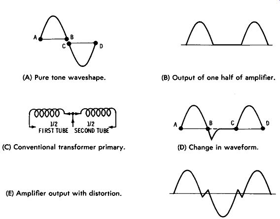
Fig. 5-19. Waveforms in push-pull stage.
The unity-coupled circuits in their simplest form use only one half of a conventional push-pull transformer, as shown in Fig. 5-20A. The coupling under this condition is nearly 100 percent of unity.
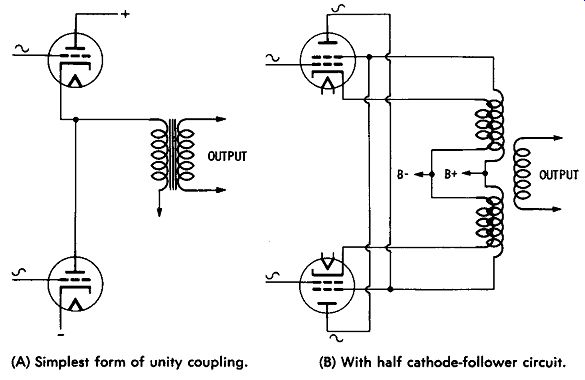
(A) Simplest form of unity coupling. (B) With half cathode-follower circuit.
Fig. 5-20. Use of unity coupling.
However, it is still desirable to use two transformer windings so that only one power supply is needed. In McIntosh unity-coupled circuits, both wires are wound side by side for their entire length, as shown symbolically in Fig. 5-20B. Having such a close physical relation, the two wires are within a very small fraction of 100 per cent coupling. No notch distortion is developed at high frequencies, as shown in Fig. 5-19A. An additional advantage of this circuit improvement is that more transformer turns can be used at low frequencies to reduce distortion there, too. Therefore, unity coupling improves both the high-frequency performance and the low-frequency performance.
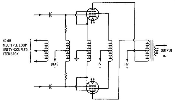
Fig. 5-21. McIntosh Pentafilar winding arrangement.
The McIntosh unity-coupling circuit is unique in one other respect. Both output tubes are used in semi-cathode-follower circuit arrangements, providing better stability in the output circuit.
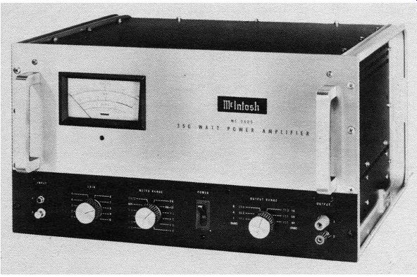
The circuits shown in Figs. 5-18 and 5-21 are for the unit illustrated in Fig. 5-22. This amplifier uses an advanced form of the basic patented McIntosh unity-coupled output circuit and trans former. This arrangement loads the output tubes equally in both the anode and cathode circuits. It is this combination of unity coupled circuit and transformer which eliminates the output-stage distortion caused by quasi-transients in conventional circuits in high power audio applications.
The output transformer uses a Pentafilar winding arrangement.
The primary has five different windings. One of the windings is used in the cathode circuit of the output tubes. A second winding is used in the plate circuit of the output tubes. The third and fourth windings are used for proper connection of the bias and screen-grid voltages to the output and driver stages. The fifth winding supplies the feedback signal for two negative-feedback loops. In this unity- ...
Courtesy McIntosh Laboratory Inc.
Fig. 5-22. McIntosh 350-watt single-channel amplifier using tetrodes and unity coupling.
...coupled feedback, one loop is the push-pull coupling to the balanced driver stage. The other, the main feedback loop, couples the feed back winding to the input differential amplifier. The windings are all wound on the transformer at the same time. This winding technique, developed and perfected by McIntosh, results in extremely tight coupling which reduces leakage inductance.
A greater amount of negative feedback can be obtained in an amplifier using primary feedback. The stability of the amplifier is not affected. If the feedback winding is wound with its turns side-by-side with those of the primary and has the same number of turns, the feedback winding will have the same phase and voltage as the primary windings for frequencies up to 500 kHz. Therefore, it is unity coupled with the primary.
By using unity-coupled negative feedback, it is possible to obtain up to 40 dB of feedback with very good stability and extremely low nonlinear distortion. It is relatively easy to maintain a flat frequency response with very low phase shift in the electronic circuits of an amplifier prior to the output transformer.
To achieve flat frequency response well beyond 20 kHz, very close coupling is required between the primary and secondary windings in the output transformer. This is accomplished by dividing the Pentafilar primary into ten different winding sections. The secondary is divided into eight different winding sections. These winding sections are then interleaved. This expensive and difficult winding method provides optimum coupling and holds the shunt capacitance to a minimum.
There are other variations of circuits for connecting the output tubes to the speaker, such as that shown in Fig. 5-23. This circuit is essentially a single-ended push-pull stage. The output tubes are in series in regard to the plate-current swing, and the grids are in push-pull. When the current rises in one tube, the current in the other falls. This gives the same result as the operation of a conventional push-pull output stage. The primary advantage here is the reduction of switching transients and a high degree of linearity without special transformer windings.
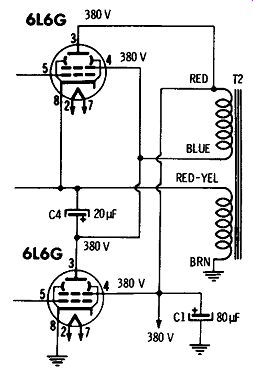
Fig. 5-23. Single-ended push-pull amplifier circuit.
Fig. 5-24A shows the application of power transistors to high fidelity amplification in a simplified class-B circuit. Class-A amplifier circuits are usually utilized for preamplifiers with transistors, but a disadvantage of class-A operation in transistor power-amplifier circuits is the requirement that there be collector current at all times.
When two transistors are connected in class-B push-pull, one transistor amplifies half of the signal, and the other transistor amplifies the other half of the signal. These signals are combined in the out put circuit to restore the original signal in an amplified state.
Transistors are not usually used in true class-B operation because of an inherent nonlinearity, called crossover distortion, that produces a high degree of distortion at low power levels. The distortion results from the nonlinearities in the transistor characteristics at very low current levels. For this reason, most power stages operate in a biased condition somewhat between class A and class B. This intermediate class is defined as class AB. Class-AB transistor amplifiers operate with a small forward bias on the transistor to minimize the nonlinearity. The quiescent current level, however, is still low enough that class AB amplifiers provide good efficiency. This ad vantage makes class-AB amplifiers an almost universal choice for high-power linear amplification, especially in equipment operated from a low-voltage supply.
Fig. 5-24B shows a transistor amplifier with the output transformer eliminated. The advantages of class-B or AB operation utilizing transistors can be obtained without the use of an output transformer.
In this circuit, the secondary windings of driver transformer T1 are phased so that when there is a negative signal from base to emitter of transistor Q1, there is a positive signal from base to emitter of transistor Q2, and vice versa. The negative signal to the base of Q1 causes Q1 to draw current, and the positive signal to Q2 cuts Q2 off. When the condition is reversed, transistor Q2 conducts and Q1 is cut off. Resistors R101, R102, R103, and Rl04 provide dc bias to reduce crossover distortion and to keep the transistors a little above cutoff for no-signal conditions.
Fig. 5-24C shows a simplified complementary-symmetry circuit utilizing pnp and npn transistors together in a class-AB push-pull amplifier with direct coupling to a speaker. These two transistors are connected in a single stage so that the dc current path in the output circuit is completed through the collector-emitter circuits of the transistors.
In the circuits shown in Figs. 5-24B and 5-24C, there is practically no direct current through the speaker voice coil, and direct connection is possible.
Fig. 5-24D shows a direct-coupled transistor power amplifier with excellent low-frequency response. It has the advantage of dc feed back for temperature stabilization of all stages. This feedback system stabilizes the voltage division across the 2N553 power output transistors, which operate in a single-ended class-AB push-pull arrangement. These transistors also operate class B in the Darlington connection to increase the current gain. Using an npn transistor ( 2N696) for Q3 gives the required phase inversion for driving one of the output transistors and also has the advantage of push-pull emitter-follower operation from the output of 2Nl925 input transistor Q1 to the load. Emitter-follower operation has lower inherent distortion and low output impedance because of the high percentage of voltage feedback.
The output transistors have a small forward bias of about 15 mA to minimize crossover distortion and also to operate the output transistors in a more favorable beta range. This bias is set by the voltage drop across R1 and R2, which shunt the input to the intermediate amplifiers. The intermediate amplifiers are biased at about 2 mA ( to minimize crossover distortion) with the voltage drop across silicon diode Xll. Junction diodes have a temperature characteristic similar to that of the emitter-base junction of a transistor. Therefore this diode also gives compensation for the temperature variation of the emitter base resistance of three of the transistors. These resistances decrease with increasing temperature; thus the decrease in forward voltage drop of approximately 2 millivolts per degree centi grade of the diode provides some temperature compensation.
The input transistor is a class-A driver with an emitter current of about 4 mA. Negative feedback to the base of this stage lowers the input impedance of the stage and thus requires a source impedance that is high enough that the feedback current will flow into the amplifier rather than into the source. Resistor R10 limits the mini mum value of source impedance.
About 10 dB of positive feedback is applied by way of C101 and R101. This action helps to compensate for the unsymmetrical output circuit and permits the positive-peak signal swing to approach the amplitude of the negative peak. This positive feedback is offset by about the same magnitude of negative feedback.
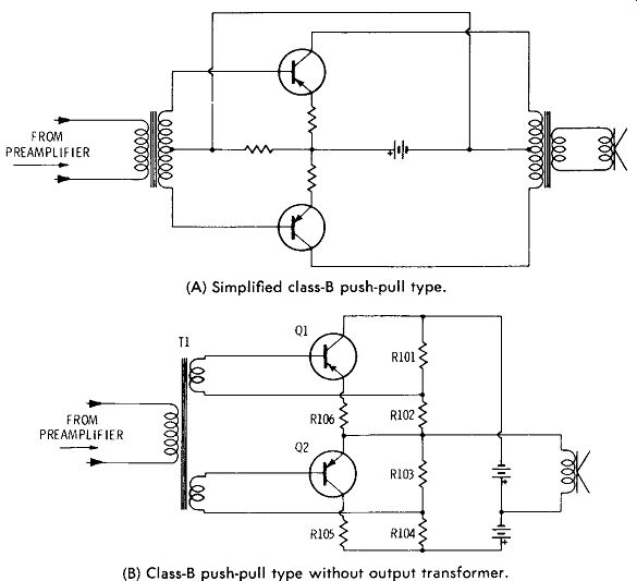
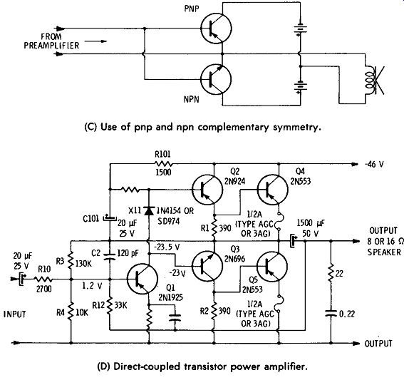
Fig. 5-24. Transistor power amplifiers.
(A) Simplified class-B push-pull type.
(B) Class-B push-pull type without output transformer.
(C) Use of pnp and npn complementary symmetry.
(D) Direct-coupled transistor power amplifier.
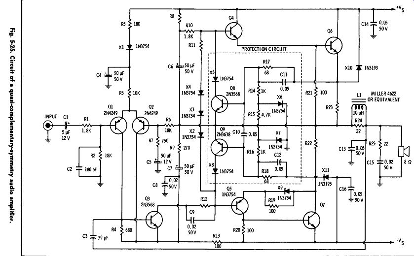
Fig. 5-25.
A ½-ampere fuse is used in the emitter lead of each output transistor for protective fusing of the output transistors and also to provide local feedback, since the ½-ampere type 3AG fuse has about 1 ohm of dc resistance. This local feedback increases the bias stability of the circuit and also improves the declining frequency response of the output transistors at the upper end of the audio spectrum. Because of possible lower transistor efficiency above 10 kHz, care should be taken when checking the maximum continuous sine-wave output at these frequencies. If continuous power is applied for more than a short period, sufficient heating may result to raise the transistor current enough to blow the ½-ampere fuses.
Since there is not sufficient sustained high-frequency power in regular program material to raise the current to this level, actual performance of the amplifier does not suffer, because the power level in music and speech declines as the frequency increases beyond about 1 to 2 kHz.
The speaker system is shunted by 22 ohms in series with 0.22 µF to prevent the continued rise of the amplifier load impedance and its accompanying phase shift beyond the audio spectrum.
The overall result, from using direct coupling, no transformers, and ample degeneration, is an amplifier with output impedance of about 1 ohm for good speaker damping, low distortion, and good bandwidth. The power response at 1 watt is flat from 30 Hz to 15 kHz and is down 3 dB at 50 kHz. At this level, the total harmonic and intermodulation distortion are both less than 1 percent. At 8 watts, the intermodulation distortion is less than 2½ percent, and the total harmonic distortion is less than 1 percent, measured at 50 Hz, 1 kHz, and 10 kHz. The performance of the amplifier of Fig. 5-24D is about the same for both 8- and 16-ohm loads.
Fig. 5-25 shows the basic configuration of a quasi-complementary symmetry circuit that provides outstanding performance in high fidelity amplifiers. This basic circuit is used for four separate audio amplifier circuits that can provide continuous sine-wave power outputs of 12, 25, 40, and 70 watts ( rms) with only minor changes in components. The input, predriver, and protection-circuit transistors remain the same for all output-power levels.
These universal quasi-complementary-symmetry amplifiers feature rugged hometaxial-base silicon npn output transistors. These transistors and the complementary driver transistors are operated class AB in an arrangement that ensures a small zero-signal current drain.
Other features of the circuit include direct-coupled preamplifier and predriver stages and short-circuit protection or safe-area limiting.
The preamplifier stage consists of a balanced-bridge circuit ( Q1 and Q2) that maintains quiescent zero dc voltage at the output.
Feedback is coupled through resistor R6, and ground reference is provided through resistor R2 and capacitor C2. The common emitters are returned to the positive supply through resistor R3, diode X1, and resistor R5. Diode X1 and capacitor C4 minimize turn-off transients and provide power-supply decoupling. The bridge circuit is direct-coupled to a class-A predriver stage ( Q3), which is coupled to the complementary drivers ( Q4 and Q5) through R12. The dissipation-limiting protection circuit is also connected at this point.
The purpose of this circuit is to prevent the output stage from being driven into conduction if abnormally high dissipation occurs. The dissipation-limiting circuit provides a shunt path for the drive cur rent from the associated driver and output devices. Resistor R12 provides some limiting of the current that transistor Q9 must support during overload conditions. Capacitor C9 bypasses R12 to improve transient response. Diodes X2, X3, and X4 and resistor R11 provide a controlled forward bias on the drivers and output devices so that class-AB operation is maintained. The "bootstrap" capacitor, C6, supplies the extra voltage swing necessary to saturate the upper output pair ( Q4 and Q6) through resistor R12. Resistor R13 and capacitor CS provide high-frequency decoupling for the negative dc supply line. Resistors R20 and R21, with R22 and R23, provide the necessary stabilization for the output transistors ( Q6 and Q7). Current is sampled across resistor R23 for positive-cycle sensing and coupled to transistor QS through resistor R17. Simultaneous voltage sampling is provided by resistor R14 and diode X6. Current is sampled across resistor R22 for negative-cycle limiting and coupled to transistor Q9 through resistor R15. Voltage sampling by resistors R15 and R16 and diode X7 causes a change in the slope of the limiting characteristics. Resistors R24 and R25, capacitors C13 and C15, and inductor L1 provide high-frequency rolloff ( above 50 kHz) so that a good margin of stability can be maintained under any loading conditions. Capacitors C10, C11, and C12 provide additional stability during limiting. Diodes X5 and XS prevent forward biasing of the collector-base junctions of transistors Q5 and Q9 during alternate half-cycle signal swings. Capacitors C14 and C16 provide parasitic suppression. Diode X9 and resistor R19 ensure a transconductance match between the upper and lower Darlington pairs to minimize low-level distortion.
Each amplifier provides the full rated power output to frequencies well beyond 20 kHz at a total harmonic distortion of less than 1 percent.
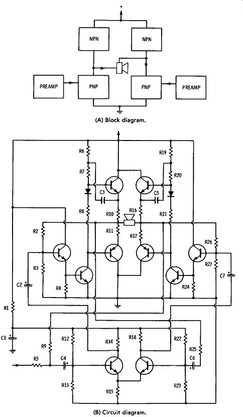
(A) Block diagram. (B) Circuit diagram.
Fig. 5-26. Bridge-type audio amplifier.
Fig. 5-26A is a block diagram of an audio-amplifier configuration that, for a given dc supply voltage, transistor voltage-breakdown capability, and load, can provide four times the power output obtainable from a conventional push-pull audio-output stage.
Alternatively, given power-output and load requirements may be achieved from this circuit configuration with half the supply voltage and transistor voltage-breakdown capabilities required for conventional circuits. This performance is possible because the load can swing the full supply voltage on each half-cycle. The load is direct coupled between the center point of two series-connected push-pull stages. This bridge type of arrangement eliminates the need for expensive coupling capacitors or transformers. These features are very attractive in applications for which the supply voltage is fixed, such as automotive or aircraft supplies.
The bridge-amplifier configuration consists essentially of two complementary-symmetry amplifiers with the load direct-coupled between the two center points. Each amplifier section is driven by a class-A driver stage that uses a transistor Darlington pair. The amplifiers must be driven 180 degrees out of phase. This dual-phase drive is provided by a differential-amplifier type of input stage, which also provides the advantage of a high input impedance.
Fig. 5-26B shows the basic circuit configuration of the bridge-type audio-amplifier circuit.
Stereo Power-Amplifier Circuits
The design features of power amplifiers for stereo are similar to those for monophonic operation. The use of two electrically separate power stages is still considered the best all-around arrangement. However, efforts have been made to design single stages that can handle both stereo signals at once.
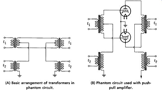
(A) Basic arrangement of transformers in phantom circuit. (B) Phantom circuit used with pushpull amplifier.
Fig. 5-27. Two-channel amplifier derived from phantom-type telephone circuit.
[Do not be confused by the use of this word in connection with a third, "middle" speaker and its associated circuit, discussed later. ]
An example of a "two-way" amplifier, sometimes called a biortho or simplex system, is one developed from the long-used telephone "phantom" circuit. Fig. 5-27 A shows the original phantom circuit, and Fig. 5-27B shows how the principle can be applied to a push pull amplifier. The basic part of the circuit is a conventional push pull amplifier, as shown in the upper portion of Fig. 5-27B. The push-pull amplifier uses input and output transformers. A second channel is added by inserting additional input and output trans formers in series with the return leads from the center taps of the transformer windings. The signal voltage from the extra input trans former is applied through the halves of the regular input transformer to the grids of the tubes in phase. This signal does not interfere with the regular signal because it cancels out in the primary winding of the regular output transformer. However, this extra signal does change the instantaneous voltage on both grids in the same way at the same time, thus causing both tube plate currents to do the same thing. Although the plate-current fluctuations from this source can-eel out as far as the regular output transformer is concerned, they do cause the same fluctuations in the total plate current into the center tap. This total current passes through the extra output trans former, whose secondary winding delivers the output from the extra channel.
The circuit of Fig. 5-27 could be used for stereo by applying the L signal to the regular push-pull channel ( E1 ) and the R signal to the extra circuit ( E2 ). However, there are serious disadvantages to this.
One is that the extra circuit operates as a single-ended ( rather than push-pull) amplifier with the tubes in parallel. This type of circuit is much more subject to distortion than is the push-pull amplifier, and its power-handling capability with tolerable distortion is much lower. Since the L and R signals usually do not differ very much in amplitude, the lopsided arrangement would be inefficient.
To overcome this objection, the circuit is rearranged to use sum ( L + R) and difference ( L - R) signals. The sum signal carries most of the power of the stereo information. Since the L and R signals are usually nearly equal, the difference ( L - R) signal is relatively small-it is the difference between two signals which are almost the same in amplitude. This small signal is applied to the extra channel, and does not tax its relatively low distortion-free power-handling capability.
The new arrangement of the circuit is shown in Fig. 5-28. No input transformer is necessary; the - L signal is applied to one grid, and the R signal is applied to the other grid. The negative L signal is obtained simply by passing the L signal through an odd number of conventional grounded-cathode amplifiers, each of which provides a phase reversal.
In the circuit of Fig. 5-28, each tube inverts its signal, so the relative polarities of the signals across the entire transformer primary and each half of the transformer are as indicated. The result is that the signal coupled through the main transformer (T1) is equivalent to L + R with polarities as indicated by the arrows at the secondaries.
Now consider the other channel. The primary winding of trans former T2 carries current from the center tap of the primary of T1.
Therefore, this current is the sum of the plate currents of the two tubes, and the voltage has the relative polarity shown. The output of T2 is the L - R signal. This output is combined with the L + R outputs of T1 to provide the overall L and R outputs of the combi nation circuit. Although the L - R output enters into the derivation of both the L and R outputs, its amplitude is relatively small, so it can be handled as an extra output with little distortion.
Whether the simplified circuit just described or a dual power amplifier is used, there are certain switching functions usually provided in a stereo power amplifier. One of these is to provide for parallel operation for the monophonic mode. A switch is provided simply to connect the L and R outputs in parallel. If you happen to have an amplifier not so equipped, or have two separate amplifiers which you are combining, you can connect the outputs together yourself. Two things are important to remember.
1. The phasing must be correct. This is indicated by the connection that gives the most output.
2. The rules of impedance matching must be observed for most efficient operation. For example, if the speaker has an impedance of 8 ohms, each of the two parallel-connected outputs should be of 16 ohms impedance.
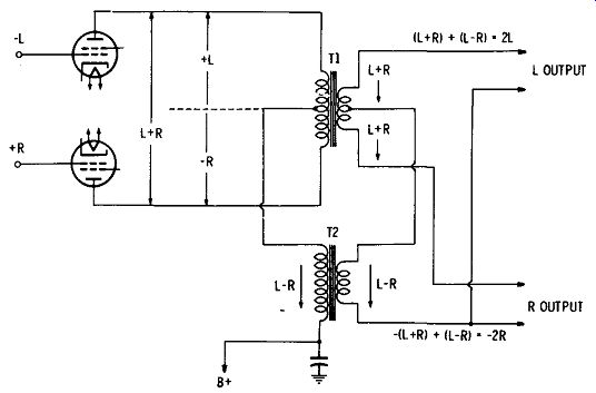
Fig. 5-28. Improved combination output circuit.
Actually, there is some doubt as to real need for such a parallel connection during monophonic operation. Many audiophiles with good stereo systems say that they find playback of monophonic recordings and broadcasts very pleasing through two channels, even though there is no stereo effect involved. Of course, paralleling does provide a single output with the power capabilities of both channels, and this may be useful under some special circumstances.
Another switching function sometimes found in the power-amplifier portion is the "quasi-stereo" switch. This switch permits either the L or the R signal alone to be fed to both channels.
Some output circuits also include a channel-reversing switch, which might more accurately be called a "channel-swapping" switch.
Operation of this switch causes the speaker that was receiving the L signal to receive the R signal, and vice versa. This is useful when the listener is checking to see if his L and R connections through the system are correct. For example, if he makes his own tape recordings, he may have an error in the connection of tape-machine outputs, and this can be quickly corrected by the "reversing" switch.
Otherwise, once your pickup cartridges and tuner outputs have been properly connected, there is no further use for this switch.
Driver-Amplifier and Phase-Inverter Stages
The amplification of the most sensitive power-amplifier stage is insufficient to provide full output from the signal of the average input device such as a phono pickup, microphone, or tuner. Additional amplifier stages are added to all power-amplifier stage designs to provide the required gain. The low driving power requirements of tetrode tubes operated class AB, as is standard in modern amplifier design, allow use of a voltage amplifier, a driver, and inverter stages with low-power outputs. These can be operated on a linear portion of the tube characteristic and produce sufficient gain per stage in such a manner that usually two to four stages, according to the particular design, can produce more gain than required.
The voltage amplification is usually accomplished in one, two, or three of these stages, and then the signal is fed to inverter and driver stages to provide two components of input signal 180 degrees out of phase with each other to drive the push-pull power-output stage.
There are various arrangements for providing linear, undistorted, low-level power for driving the final amplifier. Block diagrams of various arrangements are shown in Fig. 5-29.
-------------------
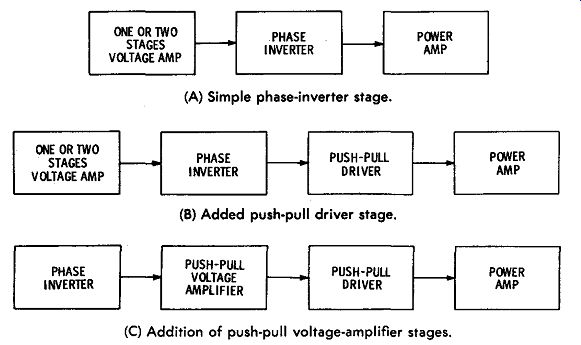
(A) Simple phase-inverter stage. (B) Added push-pull driver stage. (C) Addition of push-pull voltage-amplifier stages.
Fig. 5-29. Block diagrams of various amplifier arrangements.
--------------------
Sensitive, high-gain tetrode power-amplifier stages require comparatively small driving power and are usually connected directly to a simple cathodyne phase-inverter stage as shown in Fig. 5-29A, even though the gain of the cathodyne phase inverter is less than unity. In this case, design requirements are simple, as the cathodyne is fairly foolproof and develops negligible distortion.
Where the power amplifier has a low amplification factor, as when straight class-A operation is used, more power must be provided, and a circuit such as that in Fig. 5-29B may be used. The advantage of this will be found in the power-amplifier operation only because each added push-pull stage must be balanced, stable, and most care fully designed to eliminate distortion to feed the final amplifier stage properly.
The circuit shown in Fig. 5-29C is used in one of the top-brand amplifiers and has been designed with considerable care to achieve balance throughout the push-pull voltage-amplifier stages. Such a design is practical for use in laboratory-type equipment.
Phase Inversion
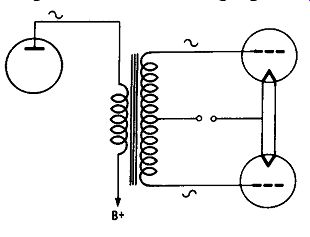
Fig. 5-30. Phase inversion with a transformer.
The signals at the grids of the power stage must be as nearly 180 degrees out of phase and equal in amplitude as possible at all audio frequencies. Since the input and preamplification stages are almost always of single-ended design, it is necessary to split the amplified signal into two equal components, one lagging the other by exactly one half-cycle ( 180 degrees). The simplest device for splitting the phase is a transformer with a single input winding and a center-tapped output winding ( Fig. 5-30). Such a transformer will provide the required phase split and equality of amplitude but at a considerable expense. An input trans former of this type must be specially designed and constructed.
It is large and heavy and, generally speaking, impractical as compared with the simplicity and low cost of resistance-coupled phase inverter circuits such as those shown in Figs. 5-31 and 5-32.
Fig. 5-31 shows various commonly employed tube-type phase inverters. The circuit shown in Fig. 5-31A utilizes a self-balancing arrangement. The incoming signal drives the grid of the upper tube, ...
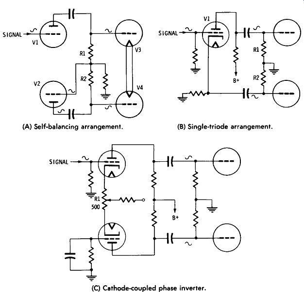
(A) Self-balancing arrangement. (B) Single-triode arrangement. (C) Cathode-coupled phase inverter.
Fig. 5-31. Phase-inverter circuits.
... V1. The output of V1 drives the upper tube ( V3) in the power amplifier, and a portion of this same output feeds through to drive the grid of V2. The output of V2 is 180 degrees out of phase with the input; therefore, the phase has been inverted as required.
The cathodyne circuit shown in Fig. 5-31B is the most commonly used phase inverter in tube-type equipment because of its simplicity and because it is self-balancing. The signal fed to the grid of V1 is reversed 180 degrees at the plate but is in phase at the cathode, thereby splitting the phase in accordance with the requirements for driving the power-amplifier stage. The same value of current flows through R1 and R2 ( equal values of resistance), therefore causing balanced output to each tube in the power amplifier.
The circuit shown in Fig. 5-31C is called a cathode-coupled phase inverter. This circuit has provision for equalizing the outputs from the two sides by adjustment of R1 ( with signal applied). This latter circuit is generally used when one or more push-pull voltage amplifiers follow to drive the power amplifier.
In the split-load transistor phase-inverter stage shown in Fig. 5-32A, the output current of transistor Q1 passes through both the collector load resistor ( R4) and the emitter load resistor ( R3). When the input signal is negative, the decreased output current causes the collector side of resistor R4 to become more positive and the emitter side of resistor R3 to become more negative with respect to ground. When the input signal is positive, the output current increases, and opposite voltage polarities are established across resistors R3 and R4. Thus, two output signals which are 180 degrees out of phase with each other are produced. This circuit provides the 180-degree phase relationship only when each load is resistive and constant throughout the entire signal swing. Other transistor phase-inverter arrangements are shown in Figs. 5-32B, 5-32C, and 5-32D.
Voltage Amplifiers
The gain of power-amplifier stages is relatively low, and phase inverter stages usually have less output than input. The average amplifier requires several additional stages with high gain per stage to bring the signal up to sufficient level to obtain full output according to the power-stage capabilities. Further, basic power amplifiers usually require a separate preamplifier with output voltages of 1 to 2 volts to drive the amplifier to full output.
These stages are operated as low-power, high-gain voltage amplifiers. Voltage amplifiers are almost always resistance coupled, operating on a small and straight portion of their characteristic curve and providing considerable voltage gain with negligible distortion.
Pentodes are used for highest gains, and triodes are used for greatest stability. One to three voltage amplifiers are usually contained in a basic amplifier, according to the sensitivity and gain requirements.
Good voltage-amplifier design can be achieved with negligible distortion of the signal, but it is not so easy to keep down internal noise and hum pickup. Special design arrangements have been made to reduce noise and hum. Hum can be reduced by use of special isolated filament circuits with short and shielded leads carrying alternating currents. Another attack is to use direct-current filament supplies. Low-noise design has also been improved by use of special input tubes and circuits and other components, such as low-noise transistors, resistors, and controls.
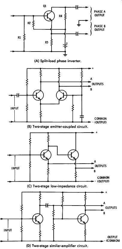
Fig. 5-32. Transistor phase-inverter circuits.(A) Split-load phase inverter. (B) Two-stage emitter-coupled circuit. (C) Two-stage low-impedance circuit. (D) Two-stage similar-amplifier circuit.