Negative Feedback
In the dynamic operation of a modem basic amplifier, there is usually provided feedback of a portion of the output signal to the input stage. This feedback is negative, or, in other words, a cancelling signal fed in opposite phase with respect to the input signal at the feedback point. This feedback signal is superimposed on the original signal to reduce distortion and noise originating from within the amplifier. Negative feedback also lowers the effective output impedance and provides better speaker damping. The only disadvantage of negative feedback is that it reduces the overall amplifier gain considerably. However, this loss of gain can be re covered by use of an additional voltage-amplifier stage as found in modem arrangements.

Fig. 5-33. Negative-feedback loop.
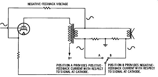
Fig. 5-34. One-stage voltage and current feedback circuit.
Fig. 5-33 shows a block diagram of an arrangement using a negative-feedback loop. Fig. 5-34 shows a feedback circuit arrangement in one stage only. Negative-feedback voltage may be fed back over one or any odd number of stages.
With application of negative feedback, noise and distortion are reduced by cancellation. With no signal input, any internally generated noise has a signal component fed from the output back to the input as shown. Since this feedback signal is opposite to the internally generated noise, when the feedback is adjusted so that the noise portion of the feedback signal is proportionately equal to the average generated noise over the feedback loop, a large portion of the noise will be cancelled out. The same is true for hum internally picked up, providing the phase of the hum is suitable for suppression.
The same principle of cancellation applies to distortion of the original signal originating within the amplifier at any point within the feedback loop. An internally distorted signal waveform will be pulled back toward the original signal shape. The original signal will be reduced, but additional components added internally to the original signal will tend to cancel out.
The effective output impedance of the amplifier is lowered by means of the variation in the amount of negative feedback applied in relation to the output load. The negative feedback is taken off the output of the amplifier in the same manner as the speaker takes power. When the speaker is not taking power, the relative output signal voltage rises, and consequently there is proportionately more negative-feedback voltage. More negative feedback reduces the gain and lowers the output signal, tending to compensate for the un loaded condition of the output. In this manner, negative feedback has the same effect as lowering the output impedance of the system.
Negative feedback of an amplifier is rated in dB. The feedback dB rating is equal to the reduction in gain of the amplifier caused by the negative feedback.
Positive Feedback
Just as negative voltage feedback lowers the output impedance of an amplifier system, positive-feedback voltage will increase the effective operating output impedance. Positive-feedback voltage, if applied in the same manner but opposite in phase to negative feed back, will cause system oscillation at random audio frequencies.
Current feedback applied from the output of the amplifier to the cathode of an intermediate amplifier stage will cause opposite effects on output impedance. Positive-feedback current will lower the effective output impedance, and negative-feedback current will raise the effective output impedance of an amplifier. Positive-feedback cur rent will also increase distortion in a manner opposite to the cancellation principle of negative feedback.
Variable Damping
This feature of amplifier design does not improve amplifier performance. It is incorporated in some amplifiers to provide better speaker operation. Variation of the effective output source impedance of an amplifier, as can be provided by voltage and current feed back controls, will provide an adjustment for best loading and damping for any particular speaker arrangement. Fig. 5-34 shows how simple combinations of voltage and current feedback circuits with an amplifier can be arranged to obtain any value of output impedance and damping factor desired. In Fig. 5-34, when the switch is at position A, positive-feedback current and negative-feedback voltage are fed back to the input to lower the output impedance and increase the damping factor of the system. When the switch is at position B, negative-feedback current and negative-feedback voltage are used to raise the output impedance and lower the damping factor. Fig. 5-35 shows a circuit arrangement used in a popular amplifier kit to provide continuously variable damping designed to provide complete dynamic matching of the amplifier to any speaker according to individual taste.
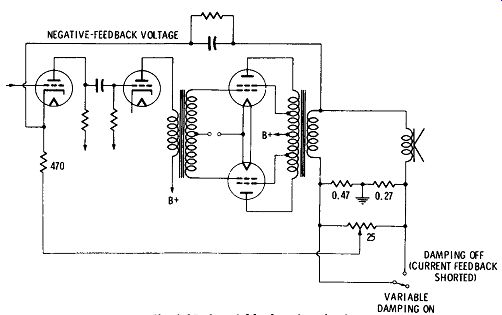
Fig. 5-35. A variable damping circuit.
Basic amplifiers usually require about 1 volt of signal into a load resistance of 100,000 to 300,000 ohms to drive them to full output.
Tuners usually provide this amount of drive, so a preamplifier is not required to increase gain when only tuners are used.
High-output phono cartridges and microphones provide sufficient output ( up to 1 volt) to drive some basic amplifiers, but high fidelity phono pickups and microphones of the magnetic or dynamic type give considerably lower outputs. The lower the output, the easier it is to design quality characteristics into these pickup units.
To develop sufficient signal to drive a basic amplifier to full output, additional amplification or preamplification is required before feeding the basic amplifier. This gain is usually provided by a pre amplifier, preamplifier-equalizer, or control center. Preamplifier equalizers and control centers are also designed to provide all kinds of control adjustment, compensation, and filtering to cover about every condition one would desire, as has been described.
A low-output phono pickup feeding a simple preamplifier with one or two stages provides sufficient gain to drive a basic amplifier which needs up to 3 volts for full output, but when various arrangements of compensation filtering networks and feedback circuits are employed to develop special effects these features have circuit requirements that reduce the overall gain by an amount greater than the compensation provided. For instance, if 20 dB of treble boost and attenuation are provided, a total of 40 dB range of control is applied. If the amplifier is to provide a gain of 50 dB under flat operating conditions, then it must provide for an output level of 50 dB at the reference frequency, which is usually around 500 Hz, plus 20 dB at boost frequencies. The full attenuation of the highs or lows will also cause reduction of the overall gain at the reference frequency so that more than 50 dB of gain at the reference frequency at flat setting is required--an average design might require 10 dB of additional reference-frequency gain to cover all conditions of treble and bass attenuation-curve variations and overlap. Therefore, in order to provide for bass and treble boost of 20 dB, that much more gain ( 10 dB) must be added. If 20 dB of negative feedback is collectively applied, then the gain of the amplifier should be at least 50, plus 10 for overlap, plus 20 for boost, plus 20 for negative feedback as described, or a total of 100 dB of amplification to provide 50 dB of effective gain because of these provisions. There are other provisions in the more complex control units that require even more gain; thus arises the reason for more stages and complexity as more features are incorporated in the unit.
Compensation
There are several forms of compensation provided in preamplifiers and control units. One form of compensation is equalization of the highs (attenuation) and lows (boost) to compensate for emphasis and de-emphasis, respectively, of the highs and lows in the processing of high-fidelity records, as described previously. Current hi-fi records are cut with a curve like that shown in Fig. 5-3, as has been described. Equalizing circuits in preamplifiers and control centers must have provision to compensate for this by amplification compensation curves of closely equal and opposite form, as shown in Fig. 5-4. These curves show equalization for most all records cut today as per Record Industry Association of America ( RIAA) standards. However, there are several other curves to which many popular records are still being made from old master recordings. These curves are shown in Fig. 5-36. Equalizers will have to provide for these as long as the older recordings are played. This requires more switching circuits. Another form of compensation is to equalize for emphasis of highs used in fm broadcasting techniques and to compensate for the loudness effect of the human hearing system, as described previously.
All these compensating effects are usually provided by various arrangements of high-pass and low-pass filters. These filters are placed in series with some channel of the preamplifier according to their use, or they are inserted in negative-feedback loops to attenuate by discrimination of feedback at certain frequencies and at the same time to reduce overall distortion.
Record equalization is usually selected by a single rotary switch control. More elaborate systems provide additional finer adjustment of rolloff and turnover frequencies to suit personal taste.
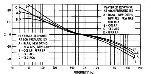
Fig. 5-36. Comparison of standard RIAA playback curve with some curves
used before the present standard was adopted.
Equalization rolloff points and slopes are controlled by switching in varying amounts of capacitance, resistance, or inductance in the high- and low-pass filtering circuits as described. Almost all modern records are being cut to one standard, so this provision is mainly useful for compensating for odd records and to give considerable flexibility for experiment or to compensate for other conditions according to the critical listener's taste.
A modem high-fidelity system may have many sources of program material: phono pickup, a-m or fm tuners, television, tape, microphone, and others. Control centers are available with any degree of complexity one might desire to provide conveniently for the many kinds of inputs, to switch from one to the other, apply power to several program sources, control or alter the signal, mix programs, and in general perform the many operations used in advanced high fidelity techniques.
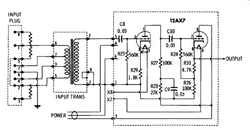
Fig. 5-37. A simple pre-amplifier circuit.
NOTE: I - DC VOLTAGES TAKEN WITH 20,000 OHMS-PER- VOLT METER AND SHORTED INPUT. 2 - AC VOLTAGES TAKEN AT 1 kHz WITH 2-MEGOHM AC VTVM. 3 - All RESISTORS ±10% CARBON UNLESS SPECIFIED.
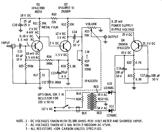
Fig. 5-38. A tape preamplifier circuit.
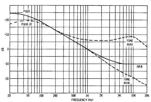
Fig. 5-39. Frequency response in series with head, for circuit shown
in Fig. 5-38.
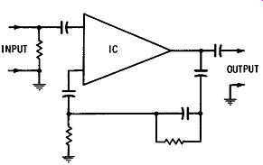
Fig. 5-40. Integrated pre-amplifier circuit with equalization network.
PREAMPLIFIER CIRCUITS
A simple tube-type preamplifier is shown in Fig. 5-37. The plug-in unit shown is the simplest form of preamplifier including only an input matching circuit, a straight amplifier working on the linear portion of its curve, and an output to match the power-amplifier input.
The purpose of this unit is to match the input device, such as a phono pickup or microphone, to the input circuits of the amplifier and to increase the input signal from such low-output devices as a dynamic microphone sufficiently to drive the amplifier to full output.
The prime advantage of such a unit is its obvious simplicity.
The transformer provides a multi-match for input devices having impedances from 50 to 20,000 ohms. The output matches a 100,000 ohm or high-impedance input of a basic amplifier.
Where no control, compensation, or filtering is desired, this unit will provide all that is needed. This is especially suitable to micro phone application.
Fig. 5-38 shows a circuit of a simple preamplifier specifically designed for tape. This preamplifier includes (NAB) variable equalization for tape speeds from 1 7/8 ips to 15 ips. See Fig. 5-39. The maximum output into a high-impedance load is 6 volts rms. This unit must be fed to an amplifier with a 10-foot or shorter shielded lead.
There is a similar model with one stage added and an output transformer to match a 600-ohm balanced line. Taps are provided for 1500-, 150-, and 6-ohm loads. A 600-ohm line up to several hundred feet long can be used.
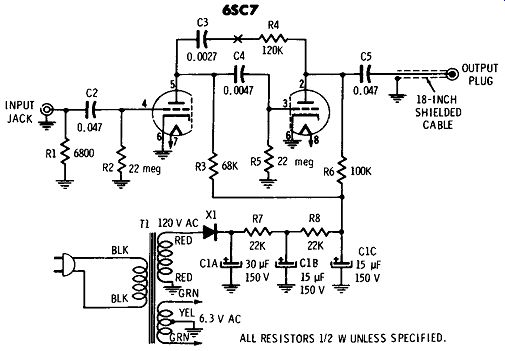
Fig. 5-41. A preamplifier with fixed equalization.
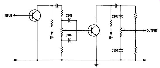
Fig. 5-42. Two-stage preamplifier with separate bass and treble controls.
Fig. 5-40 illustrates the use of an integrated-circuit preamplifier.
The external resistor-capacitor network shown is used with the IC to provide equalization. Figs. 5-41, 5-42, 5-43, and 5-44 show pre-amplifier circuits of simple design, but each successive unit has progressively more complex circuitry. Fig. 5-41 is a two-stage amplifier with impedance-matching and gain characteristics similar to those of the unit in Fig. 5-37, but in addition it has fixed equalization to compensate for average pre-emphasis and de-emphasis of recordings. The purpose of this unit is to match the output of high fidelity, low-output magnetic phono pickup cartridges, to increase the signal, compensate for record playback, and match a basic amplifier input. Equalization is achieved by use of R1 to roll off the highs, and C3 and R4 to provide low-frequency compensation. The feedback loop is negative and tends to remove any internally generated distortion or noise as well as provide attenuation for compensation.
This unit also can be used for straight public-address work or microphone input by removing the equalization circuits.
While older records had many variations in emphasis rolloff frequencies, the variations are small enough that the circuit shown in Fig. 5-41 will do a reasonable job on all of them. ( See Fig. 5-36.) However, if it is desired to be able to compensate closely for the original emphasis conditions, more elaborate units with several equalization filter circuits and components that can be switched in are available.
Fig. 5-42 shows a circuit with the same functions but with controls added in a transistor circuit. The tone-control network has two stages, with separate bass and treble controls. The frequencies for boost and cut are controlled by the values of C101, C102, C103, and C104. Loading of output and input must be compensated for when added according to value.
Phono Preamp and Control
The unit shown in Fig. 5-43 is similar to and used primarily for the same purposes as the unit shown in Fig. 5-41. This unit provides amplification and equalization of the signal from a hi-fi magnetic pickup, but it has the added feature of equalization selection. Examination of the circuit reveals additional switching for control of low- and high-frequency compensation. Low-frequency compensation circuits are adjustable by switch SL High-frequency rolloff is accomplished by the capacitors selected by S2.
The method of attenuation in the circuits shown in Figs. 5-41 and 5-43 is degenerative. The component frequencies that are desired to be attenuated are fed back negatively, and those that are not desired to be attenuated are fed back in such a manner as to achieve proper emphasis and de-emphasis.
Equalization is also achieved in a simpler but effective manner by high- and low-pass filter arrangements inserted in series with the amplification circuits, as in Figs. 5-42 and 5-44.
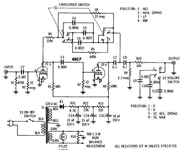
Fig. 5-43. A preamplifier with variable equalization.
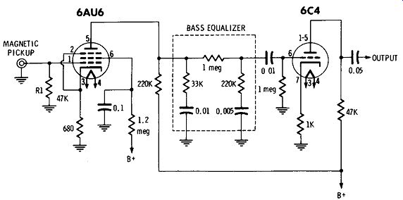
Fig. 5-44. A preamplifier with series equalization-attenuation.
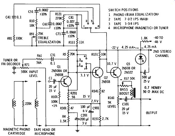
Fig. 5-45. Phono, tape, microphone, and tuner preamplifier.
The degenerative compensation circuit has advantages in the distortion and interference cancelling effects of negative feedback which is used over the entire audio spectrum; that is, if the signal is fed back so as to provide 20-dB treble attenuation, the treble is actually attenuated 30 dB and mid-range 10 dB, so that the negative feedback affects the whole spectrum.
The circuit of Fig. 5-45 shows a transistor arrangement which meets the requirements of increasing the signal level from a pickup device to about 1 volt rms. It also meets the requirement of providing compensation, if required, to equalize the input signal for a constant output with frequency when the pickup device is a tuner, magnetic microphone, phono cartridge ( mono or stereo), or tape head.
The preamplifier will match the impedances of most magnetic pickups. Input impedance to the preamplifier increases with frequency in switch positions 1, 2, and 3 because of the frequency selective negative feedback to the emitter of the first stage. The impedances of magnetic pickups also increase with frequency, but they are below that of the preamplifier.
The first two stages of this circuit have a feedback bias arrangement, with R101 feeding to the base of the first stage bias current that is directly proportional to the emitter current of the second stage. The output stage is well stabilized with a 5-kilohm emitter resistance.
The ac negative feedback from the collector of the 2N508 ( Q2) in the second stage to the emitter of the first stage ( Q1) is frequency selective to compensate for the standard NAB or the standard RIAA recording characteristics for tape. The flat response from a standard NAB recorded tape occurs with treble control R91 near mid-position.
There is about 6 dB of treble boost with the control at 30K, and approximately 10 dB of treble cut with it at zero. Mid-position of the treble control also gives flat response from a 7½-ips tape. This treble equalization permits adjustment for variations in input and output components.
A 3¾-ips recording tape head gives an equalized response with ± 1 dB variation from 60 Hz to 12 kHz. Noise level is 76 dB below reference-level output.
A good signal-to-noise ratio (S/N) can be realized with a tape head inductance of 0.4 henry. The S/N and dynamic range are improved by Rl41 in the emitter circuit of the second stage, which reflects a higher input impedance from this stage and thus increases the gain of the first stage.
The voltage feedback from the collector of the second stage decreases at lower frequencies because of the increasing reactance of the feedback capacitor in series with the treble control. In the last switch position, capacitor C41 is large enough with R81 to make the voltage feedback ( and thus the gain) constant across the audio spectrum. This flat preamplifier response can be used with a tuner, fm decoder, or microphone. The input impedance to the preamplifier in switch position 4 is about 5.5 kilohms, and a 300-microvolt input level gives a 1-volt output (70-dB gain). This sensitivity and input impedance give excellent performance with low- and medium-impedance magnetic microphones. The noise is 65 dB below the 1-volt output level. A magnetic pickup should be left connected at the preamplifier input while using the tuner or fm decoder. This tuner input has a sensitivity down to 250 millivolts.
The RIAA feedback network ( first switch position) has capacitor C71 for decreasing the amplifier gain at the higher frequencies. This eliminates the need to load a magnetic cartridge with the proper resistance high-frequency compensation. An input level of 7 millivolts gives a 1.5-volt output.
The emitter-follower output stage of the preamplifier gives a low impedance output for a cable run to a power amplifier ( transistor or tube) and acts as a buffer so that any loading on the preamplifier will not affect the equalization characteristic. The preamplifier out put should not be loaded with less than 5 kilohms, preferably about 15 kilohms.
Control-Center Preamplifier Circuit
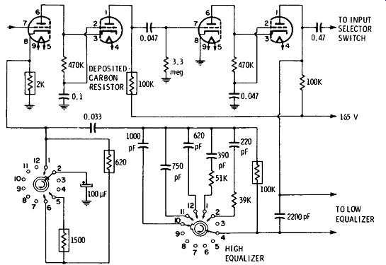
Fig. 5-46. Application of low-noise deposited-carbon resistors to reduce
input-stage noise.
It has been shown that to obtain more control features and flexibility, more gain is required and therefore more stages, circuits, and components. Quality design becomes increasingly difficult, especially at the input stage of a high-gain preamplifier. This stage is probably the most critical because of noise conditions. Any noise additional to the original signal produced or picked up in the first stage will be amplified in direct proportion to the total amplification of the input signal. If the input signal is low, as it is from magnetic and dynamic phono pickups, the first-stage noise and hum pickup must be proportionately very low not to cause noticeable interference. Hum pickup from ac-operated filaments is such a problem when low output magnetic pickups are used that several manufacturers of high-grade preamplifiers have a special rectifier and filter to provide current for the first or more stages in the preamplifier. Still further precautions are taken in designs by having a separate chassis for the power supply and a provision for dc filament supply. The real advantage of this is again experienced in the input stage. Further noise reduction is attempted by use of special low-noise resistors in loading-circuit controls and networks where carbon resistors do develop and add noise to the signal as it passes through. Circuits where these special resistors are applied-plate, cathode, and compensating networks-are shown in the schematic diagram of Fig. 5-46 from a Bogen preamplifier design. The rectangular resistor symbols represent low-noise deposited-carbon resistors.
The input section of preamplifiers and controls also contains the switching circuits for changing various input sources as desired.
One interesting arrangement having considerable flexibility is found in the master control shown in Fig. 5-47. This unit provides for seven inputs. The input stages provide the proper impedance match to the input unit. How this is accomplished is also shown in Fig. 5-47.
This unit has been conservatively designed on the following principles: ( 1) that an equipment having higher than necessary output capabilities will give better fidelity when working on a smaller portion of its overall response curve, and, ( 2) that process quality control by use of close-tolerance components in all critical circuits will ensure that each unit produced will be very similar in quality of operation to a laboratory model.
Naturally this type of unit will cost more than an ordinary model, but it has features and specifications as follows: Hum: Inaudible at full gain ( 20 volts output, whereas usually less than 5 volts is required to drive most basic amplifiers). Noise: 10 dB or more below average low-level signal input from magnetic phono pickup ( 10 m V). Intermodulation Distortion: Less than 0.1 percent at normal output (2 volts).
Frequency Response: ±1 dB from 20 Hz to 60,000 Hz.
Controls:
A. Switching ( 1) Low-level microphone ( 2) Two low-level magnetic cartridges ( 3) Fm or a-m tuner ( 4 ) Television ( 5) Phono pickup cartridge ( 6) Tape playback or monitoring ( monitor as you record)
B. Equalization compensation. Six accurate equalizer turnover positions. Six accurate treble rolloff positions.
C. Loudness compensation.
A continuously variable loudness control which is so designed as to compensate for the Fletcher-Munson hearing characteristics at various levels.
(See Figs. 1-1 and 5-48.) To obtain consistency and quality, the circuit contains over a dozen accurate low-noise resistors, a dozen low-tolerance silvered mica capacitors, and a high-Q toroidal coil for cutoff filter circuits.
Filaments operate on direct current which has three stages of hum filtering. A separate plug-in miniature power supply contributes to reduction of hum to below the thermal noise level so as to be in audible and not measurable at full gain and with full bass boost.
A variable high-frequency cutoff filter is provided for use with tuners to eliminate a-m interstation beat whistle (10 kHz). This circuit also provides positions to quiet undesirable record-surface noise, and tape and fm-tuner hiss.
There are several circuits common in principle to almost all the foregoing control centers. Among these are the bass and treble controls designed to provide from 15 to 20 dB boost or attenuation of bass or treble frequency components separately. This kind of circuit is shown in Fig. 5-47. Treble control R26 ( Fig. 5-47) and associated components provide adjustment of the high frequencies by variable high- and low-pass filtering. Bass control R27 and associated components provide a similar effect in the bass regions. These controls are arranged in high- and low-pass filter networks and made variable about a design center which constitutes the flat position when the controls are on dead center. Turning to the left droops and turning to the right boosts high- and low-frequency notes for each control, respectively.
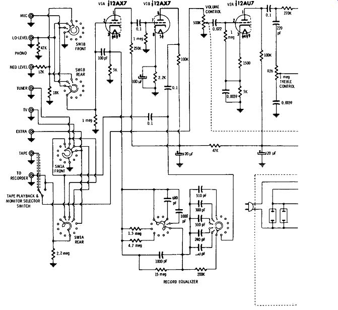
Fig. 5-47. A single-channel laboratory type preamplifier equalizer.
Another feature common to most advanced control centers is the convenience of two outputs: one to feed a tape recorder for recording one's own program material, and one to feed the amplifier system. These outputs are usually fed through a cathode-follower circuit arrangement in order to reduce the output impedance. The ad vantage of the high-impedance input and low-impedance output characteristics of a cathode-follower output circuit is that the low impedance output characteristic permits the use of long connecting lines between the preamplifier and the basic amplifier without danger of hum pickup or loss of high-frequency components of the signal.
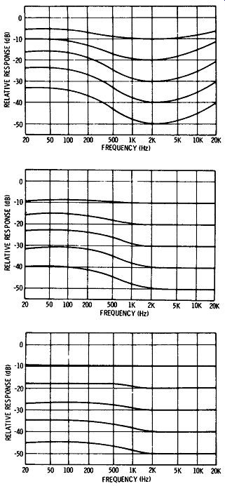
(A) Maximum position . (B) Second position. (C) First position.
Fig. 5-48. Curves showing the frequency response of the amplifier of Fig. 5-47 corresponding to various positions of the loudness control.
In preamplifiers having direct-coupled output from the plate of the last stage, a short shielded lead, preferably shorter than one or two feet, is desirable because this lead will be sensitive to surrounding magnetic fields which may induce undesired noise components.
Also, the capacitance of the lead may attenuate the highs.
A loudness control is usually furnished as a switch for a common setting or as a variable control to compensate for different degrees of human hearing response. Refer to the Fletcher-Munson curves at different audio volume levels, as shown in Fig. 1-1.
Common to all units is the volume control, either coupled to a loudness control or separate. This control is usually inserted either in one or two grid circuits or on the output side of a cathode-follower output stage. The latter has the advantage of simple uncritical design in that it does not affect frequency response in any way.
The grid-connected ganged volume control as used in the circuit of Fig. 5-47 prevents overloading by too strong a signal before it reaches the last stages of the system.
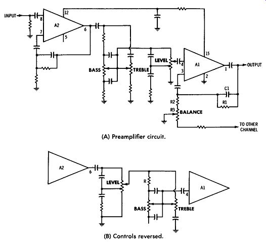
(A) Preamplifier circuit. (B) Controls reversed.
Fig. 5-49. Single-channel preamplifier using one half of integrated circuit.
Integrated Circuits for Preamplifier Service
A schematic diagram of an integrated-circuit single-channel pre-amplifier is shown in Fig. 5-49. The circuit of the integrated amplifier array is based on use of one half of an RCA 3048 or RCA 3052 16-lead JEDEC package. Tone controls and provision for balance with a second amplifier have been added. Amplifier A1 provides a flat response in the audio range, but is rolled off at about 20 kHz by capacitor CL Because each amplifier of these integrated circuits has an independent feedback point, it is possible to vary the gain for balancing when a second similar channel is added ( for stereo). With this arrangement, the gain of one channel is increased while that of the other is decreased as the balance control is varied. The result is negligible change in level throughout the range of the control.
Resistor R1 in Fig. 5-49A acts in parallel with the feedback resistance already on the integrated-circuit chip to reduce the gain.
Resistors R2 and R3 reduce the negative feedback supplied by R1.
This same amount of gain could have been programmed by omission of R1 and a corresponding increase in the values of R2 and R3.
Analysis of differential-amplifier stages has shown that the equivalent noise source resistance comes from both inputs. Therefore, the low resistor values achieved by the use of R1 result in a decrease in the noise output by about 4 dB. This noise reduction is important when the level control is at the minimum setting and the signal-to noise ratio is 0 dB. It is possible to improve this circuit under certain operating conditions by alteration of the position of the controls in the circuit. To achieve this, the equalizer and second-amplifier stages may be kept intact, but the positions of the level and tone controls should be reversed; i.e., the level control should be first and the tone controls following, as shown in the partial diagram of Fig. 5-49B. In some cases, the design of complete systems is complicated by the fact that many loudspeakers tend to overload at low frequencies.
In addition, there may be acoustic coupling between the input and output that causes an unstable microphonic condition at full gain.
With the arrangement of Fig. 5-49B, it is possible to realize a system which has a great deal of bass boost at normal listening levels, but in which the gain at the bass end is restricted as the maximum level is approached. The value of resistor R in the tone control network ( Fig. 5-49B) is made smaller in this system. At average listening levels, the difference is made up by the reduced series impedance presented by R. The treble-boost capacitor must be increased so that there is little apparent loss in treble at low settings.
The gain of the second amplifier is reduced to make the system gain equivalent at the reference frequency, but in so doing the net gain at the bass end is less. As the level control is advanced, the sensation is one of a small change in emphasis from lows to highs.
Feedback Level Control--Fig. 5-50 shows the use of integrated circuits in a preamplifier that employs feedback volume control. In a feedback-volume-control circuit, the gain, rather than the input level, of the amplifier is varied. The level control is located between the output and the inverting input between the two integrated circuits. At minimum volume, the entire output is fed back to the input. With this amount of feedback, some external stabilization is required; C1 and R1 are used to provide this stabilization.
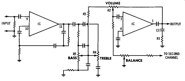
Fig. 5-50. Integrated-circuit preamplifier with feedback volume control.
The maximum gain level of the second amplifier stage is determined by the ratio of R2 and R3. Adjustment of R2 also varies the ratio of feedback resistance to source resistance. The input impedance to the second stage varies from R3 at maximum volume to R3 + R2 at minimum volume. Adjustment of R2, therefore, varies the loading on the preceding tone-control circuit. The circuit shown in Fig. 5-50 exhibits less bass boost at maximum volume than at lower levels, as does the circuit in Fig. 5-49B. To maintain bass boost at higher levels, it is necessary to scale the impedances of the tone-control circuit to lower values.
At minimum volume, the feedback-volume-control circuit effectively places the noise source for the second stage at the output of the preamplifier. Under these conditions, the source resistance seen by the power amplifier is reduced.
The feedback-volume-control circuit requires a special taper of the volume-control potentiometer. A linear taper acts rather like a switch in that it provides very little volume as the control is rotated up to about 90 percent of its rotation. The level then rises very quickly to maximum. The correct taper is a counter-clockwise logarithmic type, i.e., one in which the rate of change of resistance is very fast at first, and then slows down as maximum rotation is approached.
Stereo Integrated Circuits--Silicon monolithic integrated circuits have been designed specifically for stereo preamplifier service ( Fig. 5-51). Each package consists of four identical, independent amplifiers that can be connected to provide all the amplification necessary in a dual-channel preamplifier for a high-quality phonograph system. When a signal source is connected to the inputs of amplifiers B and D, the output of each channel may be used to drive a high-quality, high-power audio amplifier; all intermediate functions are accomplished by interconnection with the integrated preamplifier circuits. The top amplifier array is schematically identical with the bottom. Each amplifier of this unit is tightly specified for equivalent output noise under a variety of test methods. The IC's shown will perform to RIAA test specifications for equivalent input noise using one test method for amplifiers A and C, and an appropriately different method for amplifiers B and D. These circuits are supplied in a 16-terminal dual-in-line plastic package and may be operated over a temperature range of -25°C to +85°C.
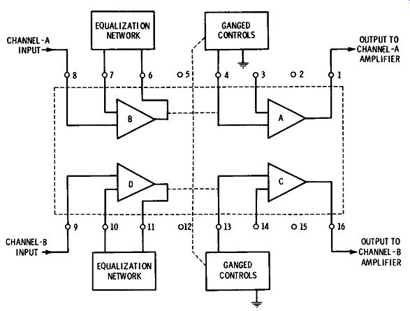
Fig. 5-51. Silicon monolithic integrated circuit for stereo preamplifier.
Fig. 5-51 shows a block diagram of the stereo ( 2-channel) pre amplifier integrated-circuit amplifier array. Each of the amplifiers provides two stages of voltage gain. The input stage is basically a differential amplifier with a Darlington transistor added on one side.
The output stage uses a combination of three transistors connected in an inverting configuration.
Input signals to the amplifiers in the array are normally applied to the noninverting input terminal to the base of a Darlington input transistor. A 0.1-meghom resistor supplies bias current for this transistor. The voltage drop across the resistor is small because the base current of the Darlington transistor is very small.
Each amplifier in these arrays may be viewed as an ac operational amplifier in which a fixed resistance is permanently connected be tween the output and the inverting input. In amplifier D, this resistance is provided by a series combination of resistors.
The amplifiers in the integrated-circuit arrays are normally operated in the noninverting configuration; it is important, therefore, to minimize the capacitance from output to input.
The gain of the first amplifier section of the preamplifier provides an increase of the signal by more than 40 dB. The gain of the first amplifier, however, is not so high that the amplifier overloads at maximum signal levels. The first integrated circuit is connected to the equalizing and compensating networks. The second integrated circuit adds more gain and provides for connections to the ganged controls desirable in stereo operations.
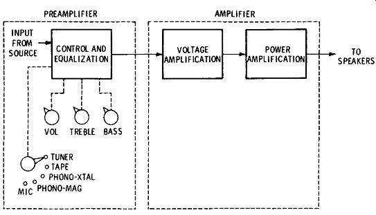
Fig. 5-52. Major divisions and functions of one channel in stereo amplifying
system.
STEREO AMPLIFICATION
The overall amplifying functions of a stereophonic high-fidelity system can also be divided into two or more channels, each having three main parts, as illustrated in Fig. 5-52. The first part, frequently physically separate, is called the preamplifier and is similar to single-channel systems. Although it amplifies the signal, its primary jobs are not amplification but: ( 1) to compensate for frequency characteristics of source material ( mainly discs and pickups), ( 2) to provide adjustment of balance among the signal components of high, low, and medium frequencies ( and for speaker compensation and listener taste), and ( 3) to provide control of loudness and other effects.
The second and third amplifier parts in Fig. 5-52 are usually combined physically into what is known as just "the amplifier." The voltage amplifier brings the signal voltage up to a level sufficient to drive the power amplifier. In addition, it provides phase splitting so that two equal signal components, 180 degrees out of phase with each other, are available to drive grids of the push-pull power amplifier. The power amplifier is very similar to the ones found in single-channel systems.
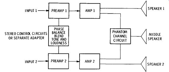
Fig. 5-53. How two amplifier controls are combined for stereo.
Basically, stereo amplifiers are different from ordinary amplifiers because they must amplify two or more separate channels rather than just one. The first stereo systems used two complete single-channel amplifiers, separate physically as well as electrically. The block diagrams in Figs. 5-53 through 5-58 illustrate how two or four amplifiers, or amplifier channels, are combined for stereo. Special features differing from monophonic arrangements may be summed up as follows:
1. Use of two or four amplifying channels, and combination of these channels physically into relatively compact arrangements.
2. Provision of additional controls, to allow adjustment of relative output amplitudes for optimum stereo effect. In many cases, volume, loudness, and tone controls for the two or four channels are ganged to simplify operation.
3. Arrangements for blending the outputs and for providing out put for additional channels and speakers when desired.
Physical Arrangements
The simplest way to provide two or four separate electrical channels is to provide two or four complete amplifiers and speaker systems, and in some cases this is done. However, this makes the system bulky and costly. Accordingly, various ways of physically combining parts or all of the amplifiers to accomplish reduction in size and cost have been devised.
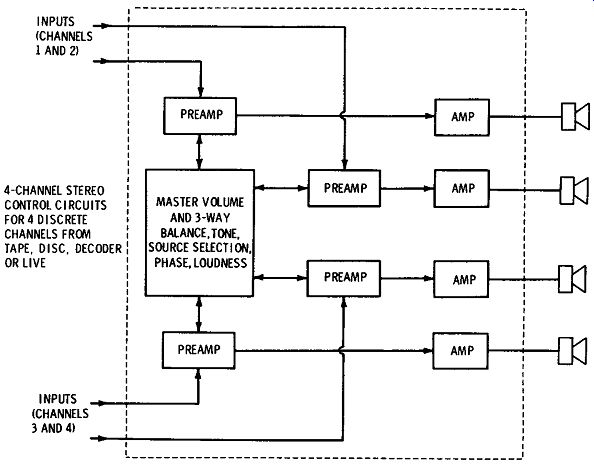
Fig. 5-54. Discrete four-channel arrangement ( 4-4-4).
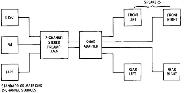
Fig. 5-55. Conversion of two-channel system to four-channel derived
stereo (2•2-4),
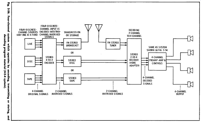
Fig. 5-56.
Just mounting two or four complete amplifiers on one chassis is sufficient to reduce weight and size considerably. A power supply of twice the current capacity is considerably less than twice as large or heavy, and the use of one, instead of two chassis ( even though it is a little larger than either of the two it replaces), makes the weight and size much less.
One interesting way that has been used to combine the two or four channels physically is the use of dual components for all stages except the power amplifier. Just as many functional sections are used, but because each pair of voltage-amplifier stages is in the same integrated-circuit package, space is conserved.
Fig. 5-54 shows the arrangement commonly used to process four discrete-channel sound from any source. The sources may be micro phones, tapes, discs, or a decoder. ( The decoder system arrangement is shown in Fig. 5-56.) Four-channel open-reel tape can provide a fine-quality, impressive performance in the home, but for average operation in home or car, tape in cartridges is most popular. Latest techniques provide for very good reproduction from cartridge tapes when Dolby circuits and chromium-dioxide and similar tapes are used.
Fig. 5-55 shows the system arrangement for a derived four channel sound system ( 2-2-4 system). In this system, the sound is decoded, or separated, after amplification.
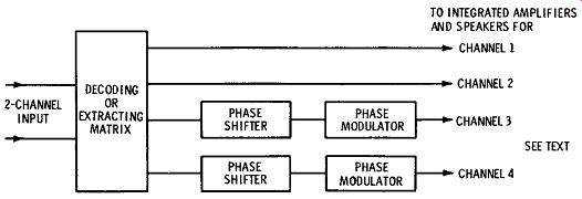
Fig. 5-57. Four-channel synthesized-sound system.
Fig. 5-56 shows the common 4-2-4 system for encoding four discrete-channel signals into two encoded or matrixed signals and then transmitting or recording the two matrixed signals for further use. To reproduce a likeness of the original sound, it is necessary to decode the two matrixed signals into four discrete signals and then to control and amplify the four signals in the manner shown in Fig. 5-54.
The stereo effect of two- and four-channel sound enhances the effect to the listener in varying degrees depending on the technique used and the program material. Generally speaking, four-discrete channel sound can provide excellent results under all conditions.
The 4-2-4 arrangements are considered next best, followed by the 2-2-4 systems. However, two-channel stereo with top-level components properly selected, installed, and operated will provide almost everything anyone could want for the home.
Fig. 5-57 shows a system arrangement for producing synthesized sound. To produce four channels from two, the synthesizer extracts selected portions of the two-channel signals and then phases and / or delays the extracted components to develop simulated space, distance, and reflection effects somewhat similar in quality to the effects of direct and reflected sounds in a large hall. This system may also provide switching to eliminate the phasing and delay operations and may provide straight decoding of encoded signals in a manner similar to the system shown in 5-56. When operated in the synthesized-sound mode, this system is a "sophisticated 2-2-4 system"; however, when this system is operated as a straight decoder, it is operating as a 4-2-4 system.
Fig. 5-58 shows a common method of converting two-channel stereo into a four-channel system using adapter-decoder-amplifier combinations available. These units vary, but generally they provide for decoding of two-channel matrixed signals, controls for balance and phasing of the four-channel output, plus outputs for four separate channel amplifiers or outputs for two channel amplifiers and provision for internal amplification of the other two channels, as shown.
2-CHANNEL
2-CHANNEL INTEGRATED INPUT AMPLIFIER WITH DECODER INTEGRATED AMPLIFIER
REAR LEFT REAR RIGHT FRONT LEFT FRONT RIGHT
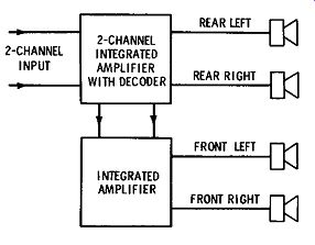
Fig. 5-58. Use of combination decoder and rear-channel amplifiers.
Control Functions
When two or more amplifying systems are used together for stereo, they cannot provide the desired stereo effect unless their operation is coordinated. Although the pioneers of stereo employed completely separate amplifiers, this required operation of multiple sets of controls, including loudness, treble, bass, and equalization selection. Having all these controls separate makes a flexible setup for controlled laboratory experiments, but is not practical for the home stereo system. Therefore, in most commercial stereo equipment, at least some of these controls are combined for greater ease of operation. Let us review the controls having special significance in stereo.
1. Balance Control--This is a combination of the volume controls of the two or four channels. It has additional significance compared with monophonic volume controls because in stereo not only the volume of the sound but also the relative volumes of sound from the two or four channels are important. A balance control for two channel stereo is usually a ganged potentiometer with one section for each amplifier. When the shaft is rotated clockwise, the output of one channel increases while that of the other channel decreases; at about mid-position the outputs are the same. Adjustment of this balance control takes care of differences in source-equipment outputs, gain of the amplifiers, difference in efficiencies and directive properties of the speaker systems, speaker locations, room acoustics, etc.
If a stereo program is being reproduced, adjustment of the balance control should make the overall source location appear to move toward the left, right, or center, depending on which speaker output is being increased.
In four-channel stereo control centers, the volume control is usually a master volume control with a four-gang potentiometer to adjust the overall volume of the four channels. In addition, there are three additional sets of ganged balance controls, one for adjustment of the volume balance of the left and right front channels, one for adjustment of the balance between the left and right rear channels, and one to adjust the relative volume balance of the front and rear sets of channels to each other. The master volume control is used to set the overall volume of the four channels, and the balance controls are set to improve the overall effect by balancing the power levels applied to the various speakers so that the desired stereo effect is achieved.
In some cases, both balance and individual volume controls are included. The individual controls are "one-time" adjustments to set the balance control. A monophonic signal is fed through the amplifiers, and the listener stands at an appropriate location for listening; then, with the balance control set at mid-position, the individual loudness controls are adjusted until the sound seems to come from a central location with respect to all speakers, and the volume is at the desired level. The volume controls can then be left set at this level and the balance control used to compensate for different types of program material.
2. Master Gain Control--Even though the volume controls are adjusted for comfortable volume during the balance adjustment, the listener may still want to adjust overall volume without disturbing balance. This is the purpose of a master gain control. One way of providing such control is to gang the loudness controls through a mechanism that allows either individual or ganged operation. Such a mechanism is now used on some amplifiers. The shafts for the controls are concentric, like those on some television controls. By pulling out on the inner shaft, the operator unlocks the controls for independent adjustment. After the balance adjustment is completed, the shaft is pushed in again, and the combination used as an overall loudness control.
3. Blend Control---This is used to "dilute" the stereo effect. It allows some of the L signal to be fed to the R or center channel or some of the R signal to be fed to the L or center channel. This control is useful mainly when pickup microphones are spaced far apart and there is too strong a left, right, or "hole-in-the-middle" effect in playback.
4. Quasi-Stereo Switch---This allows switching either the L or the R signal alone into all channels. The purpose of this is to use all channels, and thus all speaker systems, for a monophonic source; those who have tried this say it makes for more pleasing listening than with a single channel. However, with matrixed ( sum and difference) connections, such as those used in tuner multiplex, this is automatically done with monophonic material. Therefore, the main use of the quasi-stereo switch has been with a conventional tuner or monophonic pickup or tape head wherein a single channel is connected to only one of the amplifier input circuits.
5. Cartridge Paralleling---This is very important for playing monophonic discs with a stereo cartridge. As explained earlier, rumble in a turntable has a strong vertical component which can be picked up by a stereo cartridge. However, the rumble signal of one channel is out of phase with that of the other channel. Connecting the two channels in parallel for monophonic playback causes the rumble signal to cancel out. Thus, although in monophonic playback both channels reproduce the same monophonic signal, they should be paralleled for rumble reduction. In addition, the signals from the two channels combine to produce a higher-energy output when the parallel connection is used.
6. Phase-Reversing Switch---This reverses the phase of one of the stereo signals with respect to the other by simply reversing connections of the two leads carrying the signal of one channel at the input. Although this should seldom be necessary after initial setup of the stereo system, some audiophiles like to be able to change phase. They feel that in some studio programs and in some home recording experiments errors in phasing will crop up.
7. Input Equalization---Both stereo channels require the same input equalization for record and pickup characteristics as do single channel systems. For this reason, input selectors are usually ganged, with one control for both channels.
Two-Channel Stereo Adapters
The controls described in the foregoing discussion for the most part require connection into the circuits of both channels of the stereo system. This means that for the use of two separate amplifying systems not designed for stereo the owner must break into the circuit somewhere and insert these controls.
To simplify the use of separate monophonic systems for stereo, several types of adapters have been developed and are available commercially. A block diagram of such an arrangement is illustrated in Fig. 5-53. The adapter connects to both preamplifiers, either at the outputs or at a jack called "Tape Output." This jack ordinarily allows the signal from the disc or tuner into the preamplifier to be tapped off and fed to a tape machine for recording. In this case, the output can be applied to the stereo adapter.
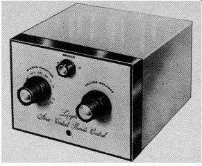
Fig. 5-59. Low-cost stereo adapter. Courtesy Lafayette Radio Electronics
Corp.
An adapter contains the essential controls that are not used in a monophonic (single-channel) system and also provides for co ordination of the two signals. The two stereo signals leave the adapter unit and are fed to two standard single-channel amplifiers arranged for stereo. A typical adapter is pictured in Fig. 5-59.
Four-Channel Adapters---Four-discrete-channel systems using four-channel tape, four channel disc (modulated multiplex disc in the 4-4-4 system mode see Fig. 5-54), or four live inputs provide optimum four-channel service, but these systems are not compatible for use with current fm broadcast equipment. Therefore, adapters for derived or matrixing systems by which four-channel information can be transmitted or stored in two-channel mediums have been developed. These are compatible with current stereo techniques in all modes ( disc, fm, tape, etc.). Four-channel stereo systems may be built by adding components such as adapters, additional amplifier units, and speakers to two-channel systems.
Such adapters may be separate units that produce derived or decoded matrix sound. Or, adapters can be obtained that are combined in several ways with two additional integrated amplifiers ( some may be had complete with four built-in channels), controls, and one or more decoders.
Derived-Four-Channel Sound Equipment ( 2-2-4)---A simple and effective adapter arrangement to convert conventional two-channel stereo sound to derived-four-channel operation ( 2-2-4) with most conventional two-channel amplifiers uses the Quadaptor system and components shown in Figs. 5-55 and 5-60. The Quadaptor system serves as a junction circuit arrangement between the outputs of a conventional two-channel stereo amplifier or receiver, and a four-loudspeaker system. It is a passive device, requiring no additional power.
Utilizing the derived system, this unit provides simple but essential circuitry to provide four different signal components from two stereo channels. Accurate electrical balance in the system is required to attain maximum separation. The unit also provides switching for listening to the front speakers alone as conventional two-channel stereo.
The Quadaptor system does not add anything to the original program, nor should it in any way materially alter the overall con tent or distortion levels of the signals. It is not a synthesizer.
A substantial portion of the recorded material in normal two channel sources is masked. The derived system makes effective use of all of the signal information, including the masked signal, by extraction of portions of signals from the total signals that have been recorded. This simple technique of ambience recovery in derived sound may reveal an added "presence" or realism to present stereo two-channel output from disc, tape, or stereo fm broadcasts, according to the program material.
The theory of operation of derived sound is described in Section 2.
Installation is described in Section 8.
Matrixed-Four-Channel Sound Equipment ( 4-2-4)---Electro-Voice, CBS, Sansui, and other makers have systems of four-channel sound that contain true matrixing systems. The home receivers of these systems are designed or adapted to decode the material that has been encoded before broadcast or before recording by the process shown in Fig. 5-56.
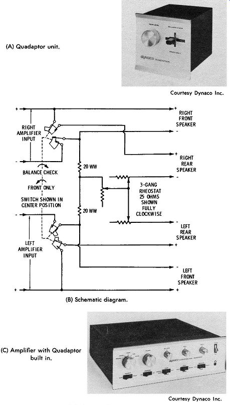
(A) Quadaptor unit. (B) Schematic diagram. (C) Amplifier with Quadaptor
built in.
Fig. 5-60. Dynaco Quadaptor.
As discussed in Section 2, two-channel fm transmission, disc, or tape may be used to carry or store the matrixed information in two channel matrixed format. A decoder at the beginning of the reproducing end of the system converts the two channels back into four with half the separation ( more or less) possible within the two channel system used to transmit or store the matrixed information signals. However, the quality of reproduction of properly arranged and operated systems should be equal to the quality of equivalent two-channel equipment, except for the enhancement that four-channel operation may provide. In the matrixed systems, the total separation between any combination of the four output channels cannot exceed the total separation between the two matrixed signals.
However, to improve performance, it is customary to increase the separation between the two front speakers at the expense of the degree of separation between the two rear speakers and the separation between front and back. The psychoacoustic relationship is similar to that of live programs in that the ear is considerably more sensitive to and able to differentiate between forward sounds than rear sounds ( front source dominance). In addition, image shift of sound to either side of the listener is vague much as secondary vision is vague to the viewer of side images.
The Electro-Voice professional encoder shown in Fig. 5-61 is the heart of the E-V Stereo-4 matrix compatible four-channel 4-2-4 system. This system allows:
1. Cutting and playback of compatible four-channel matrixed records using existing stereo equipment.
2. Production and playback of compatible four-channel matrixed tape recordings on standard two-channel recorders.
3. Transmission and reception of four-channel matrixed fm broad casts using conventional stereo-multiplex equipment.
The CBS and other encoders operate under similar principles but with somewhat different matrixing designs.
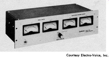
Courtesy Electro-Voice, Inc.
Fig. 5-61. Electro-Voice Model 7445 Stereo-4 encoder.
After the original signals are encoded, the resulting matrixed signals are handled and processed in the same way as conventional stereo signals. These systems of transmission and storage are economical because, except for the source equipment and some added mix-down time necessary for any four-channel origination, the only extra hardware needed to produce a four-channel matrixed program is the encoder, and this cost is borne by the producer rather than the consumer. The Stereo-4, SQ, QS, and other systems give the listener complete freedom of choice in building toward four-channel reproduction. Since these matrixed signals are compatible, they may be reproduced in conventional mono or stereo on presently owned equipment. This same equipment can be used and simply added to, to achieve four-channel reproduction.
The matrix system ( 4-2-4) provides an effective system by using two complementary pieces of equipment, an encoder at the recording studio or broadcast station and a decoder in the home. This system also permits four channels of information to be stored and retrieved with the standard two channels available on tape, disc, and fm broadcast. This is accomplished with negligible change to those specifications which affect audio quality, i.e., frequency response, signal-to-noise ratio, and distortion.
The encoder incorporates a matrix circuit which acts upon the four original stereo channels in a predetermined way to create two composite signals (channels) which may be cut on a record or broadcast by a conventional stereo fm station. The underlying principle of the matrix circuit is algebraic summation; i.e. the four original channel signals are added and subtracted in the matrix network to achieve the two desired composite (matrix) signals.
These two composite signals may be reproduced without decoding on conventional two-channel stereo equipment or on monophonic equipment, the same as with present two-channel recordings, or they may be decoded into four channel signals and played back through any four-channel system.
Input and output impedances of the encoder are usually 600 ohms, transformer coupled. On the Electro-Voice unit shown in Fig. 5-61, four front-panel meters allow monitoring of either the four input signals or the two encoded output signals. Internal gains are adjusted so that a 0-VU signal level into all four inputs produces a 0-VU level on the two encoded outputs. Indicated 0-VU is +8 dBm.
For minimum equipment investment and to maintain FCC requirements for proof of performance in broadcasting, the encoder may be installed between a four-channel tape deck and a two-channel console input. A standard four-channel hi-fi tape deck or recorder is sufficient for this purpose.
Encoded matrixed material may be processed additionally with out degradation of the recovered four channels. High-quality complementary processing methods, such as signal-to-noise stretchers, may be employed on the encoded signal with equally good results after de-processing. Non-complementary processing, such as compressors or limiters or competing equipment lines using different matrix design or arrangements, should be so connected as to act equally on all stereo channels simultaneously, or the gain and other relationships between the two encoded channels will be upset.
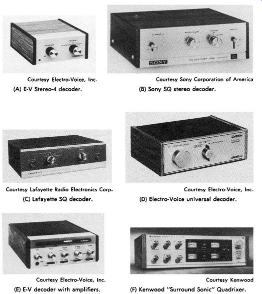
The Stereo-4 decoder shown in Fig. 5-62A has a matrix complementary to that of the Stereo-4 encoder shown in Fig. 5-61 to convert the two encoded signals back into four. The two signals entering the decoder are added and subtracted in a predetermined complementary way to derive signals similar to the four original stereo channels which entered the encoder. These in turn are fed to four independent amplifier channels and speakers. The SQ decoders shown in Figs. 5-62B and 5-62C operate in a similar manner and are designed to decode the CBS SQ matrixed signals. The decoder shown in Fig. 5-62D is designed to decode all current ...
-----------------
Courtesy Electro-Voice, Inc. (A) E.Y Stereo-4 decoder. Courtesy Lafayette Radio
Electronics Corp. (C) Lafayette SQ decoder. Courtesy Electro-Voice, Inc. (E)
E-V decoder with amplifiers. Courtesy Sony Corporation of America (B) Sony SQ
stereo decoder. Courtesy Electro-Voice, Inc. (D) Electro-Voice universal decoder.
Courtesy Kenwood (F) Kenwood "Surround Sonic" Quadrixer.
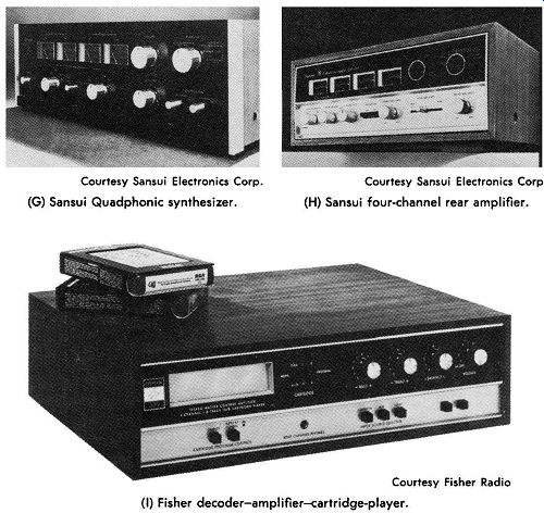
Fig. 5-62. Examples of equipment for four-channel conversion.
Courtesy Sansui Electronics Corp. (G) Sansui Quadphonic synthesizer.
Courtesy Sansui Electronics Corp. (H) Sansui four-channel rear amplifier.
Courtesy Fisher Radio (I) Fisher decoder-amplifier-cartridge-player.
-----------------
... matrix formulas, including Stereo-4, SQ, and QS, and is offered as a universal decoder.
The second outstanding advantage of the matrix system is that the decoder matrix circuitry may also provide significant enhancement to ordinary stereo recordings and broadcasts, even though they have not been specially processed with an encoder.
A four-channel matrix decoder circuit is so adjusted that it acts to separate into four channels any two-channel stereo signal fed to it.
Fortunately, due to the way modem two-channel ( un-matrixed) recordings are made with multiple microphones and multitrack recorders, when all these signals are "mixed down" to two channels, a considerable amount of positional information remains which is not discernible when reproduced in only two channels. ( Much of this information is there but masked.) This extra positional information often resembles what the matrix encoder would have produced for the recording. This extra information occurs unpredictably and varies from one recording to the next, but it can be said that virtually all modem stereo recordings do contain some degree of these additional signals. The decoder is selective and separates some of this masked information from the front channels and distributes these signal components to the rear channels, thereby allowing signals that would have been masked at the front to be heard from the rear. Thus the decoder acts upon this information in such a way that it delivers a different signal to each of the four speakers. The net effect is that most recordings exhibit a considerable amount of "four-channel information" which becomes audible or discernible only when they are played through the decoder and the signals are distributed to the four speakers.
Fig. 5-57 shows a block diagram of the internal arrangement of a type of decoder-adapter with synthesizers built in to provide simulated spatial and reverberation effects for program material that is, or is not, encoded. There are several variations of equipment for this system available, some of which are shown in Fig. 5-62.
Fig. 5-62E shows an Electro-Voice adapter-amplifier-decoder which provides easy expansion of an existing two-channel stereo system into four-channel operation. This unit contains two complete integrated amplifiers for the rear channels, a universal decoder, and full switching and control facilities for four-channel operation. The unit may be connected as shown in Fig. 5-58.
The Kenwood Surround Sonic Quadrixer is shown in Fig. 5-62F. This unit was designed to convert an existing two-channel stereo system to a four-channel stereo system by functioning in conjunction with the existing two-channel system and with an additional two-channel amplifier and two additional speakers ( four channels of amplification and four speakers altogether). In addition, this system can provide synthesized four-channel sound from two-channel sources, whether the material has been encoded or not, by reverberation or time delay adjusted to suit room acoustics.
Fig. 5-62G shows the Sansui QS-1 four-channel adapter with Quadphonic synthesizer. The QS-1 makes use of a reproducing matrix (decoder) and selective phase modulation technique to develop four-channel signals from two-channel input. The QS-1 provides high and low output levels to the amplifiers, two- and four-channel monitor circuits, input level control, four VU meters, four-channel ganged master volume control, and three balance controls for ( 1) front left to front right, ( 2) rear left to rear right, and ( 3) front to back. The synthesizer control has seven positions to provide ( 1) 2 Channel only, ( 2) Solo, ( 3) Concert Hall 1, which is not emphasized or treated and is essentially flat in response, ( 4)
Concert Hall 2, which provides exaggerated concert-hall effects ( selection and phasing of selected frequency components), ( 5) Surround Normal, to obtain a normal surround stereo effect, ( 6) Surround Quarter Turn, to reposition the sound effect by 90°, and (7) Surround Half Turn, to reposition the sound by 180°. Fig. 5-62H shows the Sansui QS-500 adapter-rear-channel-amplifier combination unit, designed to convert existing two-channel stereo systems to four-channel operation with the addition of the QS-500 and two rear speakers. The unit includes the two-channel amplifiers and controls and metering for front, rear, and front-to-rear balance.
This unit also provides a decoder and a synthesizer. Fig. 5-58 shows a diagram of how to arrange this unit and two speakers with a complete two-channel system to provide a complete four-channel system with decoder-synthesizer. The other provisions of this unit are essentially the same as those of the QS-1 shown in Fig. 5-62G. Fig. 5-621 shows a Fisher unit with two decoders ( 2-2-4 and 4-2-4), cartridge player, and integrated rear amplifier ( 50 watts). Installation of a decoder is covered in Section 8.
(A) Compact preamplifier. Courtesy Shure Brothers Inc. Courtesy Pi lot Radio Corp.
(B) Preamplifier and control unit.
Fig. 5-63. Two types of stereo preamplifier.
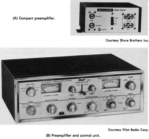
Although a few compact low-cost stereo preamplifiers are avail able ( such as the one shown in Fig. 5-63A), most stereo preamplifiers are of the more sophisticated type illustrated by the examples shown in Figs. 5-63B and 5-64. To illustrate the features of a typical pre amplifier control center and clarify the meanings of the various controls, let us take the example of the unit illustrated in Fig. 5-63B. The SELECTOR control in the upper left comer selects the input and impedance required for proper load for the source device. It has positions for microphone, tape head, phono pickup cartridge, fm and a-m tuner, tuner with multiplex, and tape-recorder inputs.
The distinction is made between a direct connection to the tape head for tape playback, in which proper loading and equalization for the head itself are necessary, and the input to the preamplifier from the output of the playback amplifier of the complete tape recorder.
The MODE switch is in the lower left comer of the unit in Fig. 5-63B. This switch allows manipulation of the two channels of the preamplifier so they can be used for normal stereo operation ( Nor mal), with the two inputs swapped (Reverse), with just channel A, or with just channel B. Just to the right of the MODE switch is the MASTER VOLUME control. This is a dual control, which simultaneously adjusts the gain of both channels. Because the MASTER VOLUME control adjusts volume without allowing for the loudness characteristic of the human ear, a LOUDNESS control ( just to the right) is also included. This is really a switch, providing stepped increases or decreases of volume in both channels simultaneously. At each step, an equalizing network compensates for the response characteristics of the listener's ear ( see Fig. 5-48). To the right of the LOUDNESS control is the STEREO BALANCE control.
In its center (up) position, it allows approximately equal gains in the two channels. As it is turned toward the right (clockwise) it increases the gain of channel B and reduces the gain of channel A until, at its extreme position, output is obtained only from channel B. When it is turned to the left (counterclockwise) it increases the gain of channel A and decreases that of channel B in the same manner. This control is used for adjustment for optimum stereo effect, which may be realized at different adjustments for different types of program material and different stereo systems.
To the right of the STEREO BALANCE control are the tone controls for adjusting the degrees of bass and treble boost. This unit differs from many others in that the BASS and TREBLE controls are step switches instead of continuous controls, and in that here the equalization for different playback characteristics ( LP, NAB, RIAA, and AEB) is provided by adjustment of the boost controls instead of at the input switch. In other units, the equalization characteristics are selected by the input selector, which will have such labels as ceramic, crystal, RIAA, etc., and continuous adjustment of the bass and treble boost is provided.
Courtesy Dynaco Inc. (A) Dynaco preamplifier-control center (assembled
or kit). Courtesy McIntosh laboratory Inc. (C) McIntosh combination tuner
preamplifier-control center. Courtesy JVC America, Inc. (B) JVC all-silicon "SEA" stereo
system preamplifier. Courtesy Harman-Kardon, Inc. (D) Harman-Kardon preamplifier/equalizer
control center.
Fig. 5-64. Examples of stereo preamplifier-control units.
Two output-level meters are shown in the upper portion of the panel in Fig. 5-63B. These are used to check the balance between the two signals during either playback or recording. The switch located between the meters transfers the meters to register for recording or playback, and the controls adjust recording gain and playback gain independently. The control in the upper right-hand corner is used to turn the unit on and off or provide connection for automatic shut-off. The later is used when the phono turntable mechanism is interconnected with the preamplifier to shut off all power when the records of a stack have all been played.
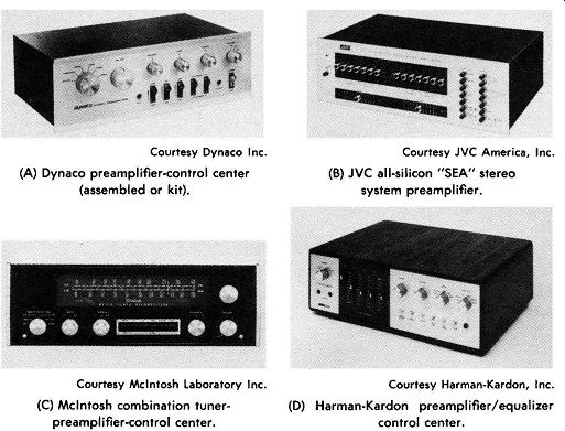
Fig. 5-64A shows a high-quality stereo preamplifier which may be purchased as a kit. Fig. 5-64B shows a stereo preamplifier which provides for finite control of frequency response and balance with a wide range of input capability. Fig. 5-64C shows a unit containing a stereo preamplifier, control centers, and built-in tuners. A block diagram of this unit is shown in Fig. 5-65.
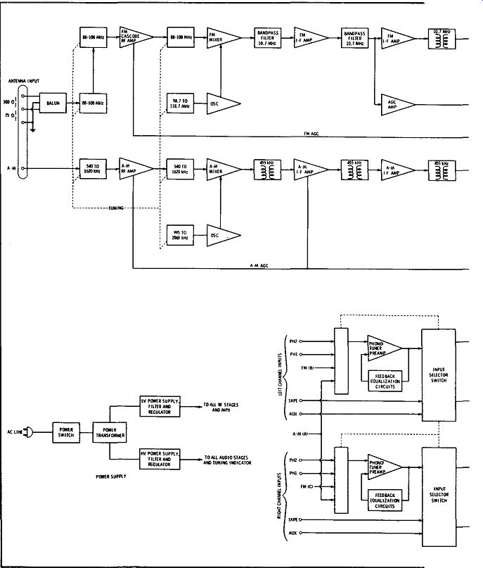
Fig. 5-65. Block diagram of McIntosh stereo preamplifier-tuner.
Amplifiers
Power amplifiers for stereo reproduction have the same requirements (electrically) as amplifiers for monophonic reproduction.
They must have sufficient output to operate the speaker system at a desirable level, low harmonic and intermodulation distortion, frequency response from 20 or 30 Hz to 20 kHz or more, and good response to transients. If any of the requirements of high fidelity for monophonic amplifiers are compromised, the full benefit of stereo reproduction cannot be realized.
The primary differences between stereo amplifiers and high fidelity monophonic amplifiers are physical in nature. First, there must be two or more separate amplifier circuits or amplifier channels. These are usually combined on one chassis. Of course, there is nothing to stop one from buying two or three separate amplifiers, but the compactness of combination units is an advantage.
Because all of the manual controls can be provided in the pre amplifier which feeds the amplifier, most amplifier units are designed with only a limited number of controls, and these controls need adjustment only once, or at the most, just occasionally. Examples of stereo power amplifiers are illustrated in Fig. 5-66. Each can be concealed completely in a cabinet, with all the controls located on the preamplifier panel.
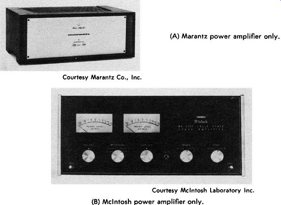
(A) Marantz power amplifier only. Courtesy Marantz Co., Inc. Courtesy McIntosh
Laboratory Inc. (B) McIntosh power amplifier only.
Fig. 5-66. Typical stereo power amplifiers.
Transistor Stereo Control Centers and Amplifier Units
The trend in hi-fi stereo design is toward multiple units on one chassis, and compactness without loss of quality. For this reason, transistors are well suited for high-fidelity control-center amplifiers.
Hum pickup from wiring, transformers, microphones, and other components is reduced because transistors do not have filaments.
Circuit arrangements and layouts can be made more efficient, due to elimination of wiring and due to the small physical size of the transistor. Shielding requirements are reduced for the same reasons.
Since transistors are low-impedance devices, they, compared with tubes, more nearly match magnetic pickups, dynamic microphones, tape decks, speakers, and lines, with increased efficiency in power transfer and reduced component requirements.
Arrangements utilizing transistor application and transistor/tube combinations with nuvistor input stages, field-effect transistors, and silicon and silicon-planar transistor types have made many new designs possible, and the state of the art continues to advance. Transistors allow reduction in size. In some cases, transformers can be eliminated.
Properly designed circuits for transistor use or transistor/tube combinations with negative feedback can provide for high-fidelity equipment the required wide frequency response and low distortion, equaling that of circuit arrangements utilizing only vacuum tubes.
It is difficult to attain faithful reproduction of all signals with transformer-coupled circuits. To have good response at low frequencies, transformers are physically large and expensive.
Transistors have made possible practical development of transformerless circuits for audio frequencies, since the transistors for audio are basically low-voltage, high-current devices. The emitter follower stage, in particular, offers interesting arrangements, since it has low inherent distortion and low output impedance.
Hi-fi stereo preamplifier-amplifiers utilizing transistors and integrated circuits throughout are shown in Fig. 5-67.
Combination Units
The trend toward combining all units except speakers into one compact cabinet is reducing cost and increasing the adaptability of hi-fi equipment to all sizes of homes. For the most exacting requirements in hi-fi, separate units still have some advantage, but the latest designs of stereo "compacts" are hard to beat. For average use, they are more than adequate, and even lower-cost models provide exceptional quality and require a minimum of space.
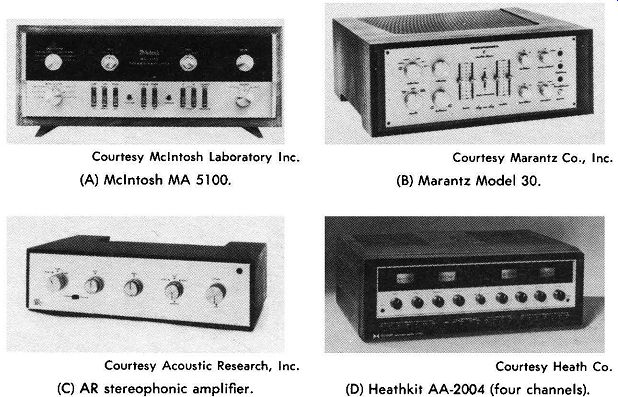
Courtesy Mcintosh Laboratory Inc. (A) McIntosh MA 5100. Courtesy Acoustic Research, Inc. (C) AR stereophonic amplifier. Courtesy Marantz Co., Inc. (B) Marantz Model 30 . Courtesy Heath Co. (D) Heathkit AA-2004 (four channels).
Fig. 5-67. Transistor stereo preamplifier-amplifier units.
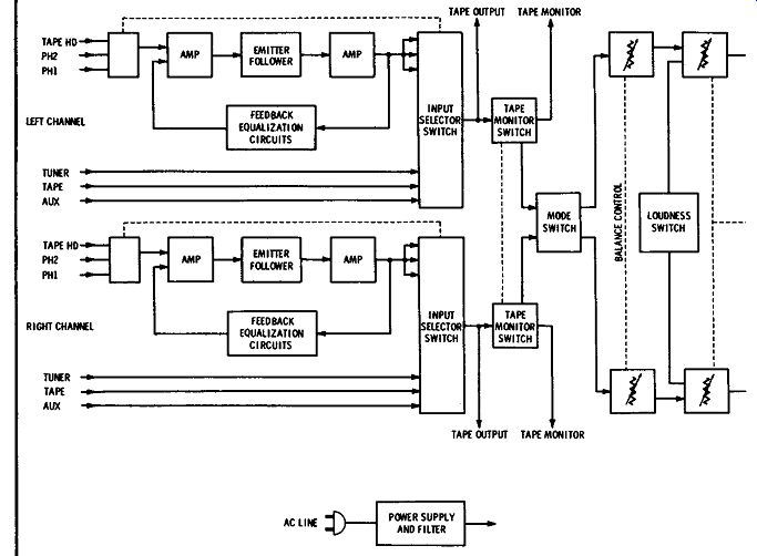
Fig. 5-68. Block diagram of McIntosh MA 5100 preamp-amplifier.
Fig. 5-67 shows preamplifier-control-power-amplifier unit combinations, all of solid-state design and high quality. Fig. 5-68 shows a functional diagram of the unit shown in Fig. 5-67 A, and Fig. 5-69 shows curves of the frequency response and distortion characteristics of this equipment.
Fig. 5-70 shows a four-channel combination integrated unit that provides preamplifiers, power amplifiers, controls for the four channels, and interrelated controls including four-way balancing among all four channels. This unit can be adapted to 2-2-4, 4-2-4, and 4-4-4 systems, and it provides for enhancing with a hall effect and quadrixer.
Fig. 5-71 shows two-channel integrated receivers which provide everything needed for hi-fi broadcast reception except the speakers.
In addition, there is a complete set of controls and preamp-amplifier ...
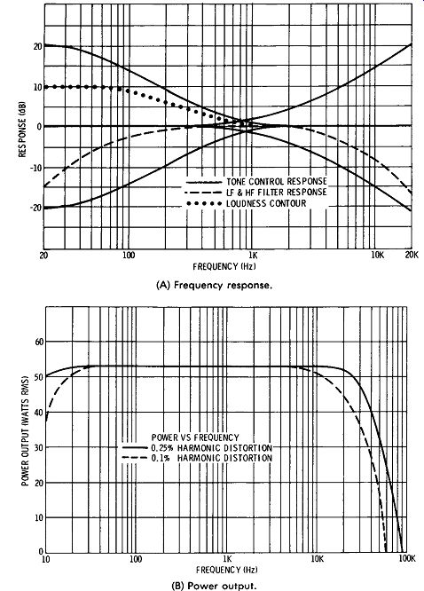
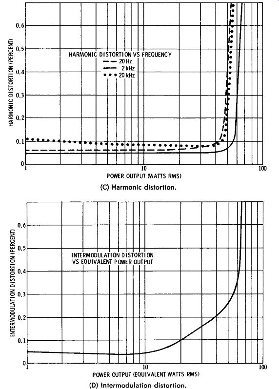
(A) Frequency response. (B) Power output. (C) Harmonic distortion.
(D) Intermodulation distortion.
Fig. 5-69. Performance curves for McIntosh MA 5100 preamp-amplifier.
Courtesy Kenwood
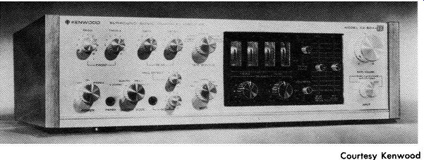
Fig. 5-70. Kenwood four-channel combination control center-preamplifier-amplifier with decoder and synthesizer.
Courtesy Marantz Co., Inc.
(A) Marantz Model 22.
Courtesy Matsushita Electric Corporation of America (C) Panasonic Model SA-6500. Courtesy Heath Co.
Courtesy Allee Lansing (B) Altec Lansing Model 725A. Courtesy Sherwood Electronics Laboratories (D) Sherwood Model SEL-200. (E) Heathkit Model AR-15.
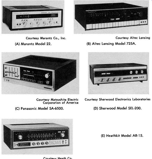
Fig. 5-71. Two-channel integrated receivers.
------------------
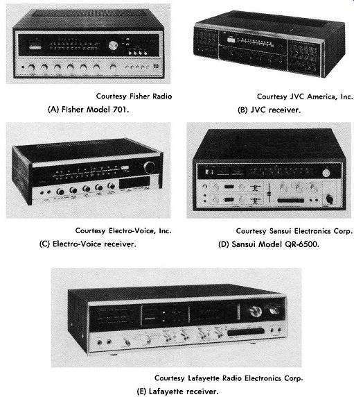
Courtesy Fisher Radio (A) Fisher Model 701. Courtesy Electro-Voice, Inc.
(C) Electro-Voice receiver. Courtesy JVC America, Inc.
(B) JVC receiver.
Courtesy Sansui Electronics Corp.
(D) Sansui Model QR-6500. Courtesy Lafayette Radio Electronics Corp.
(E) Lafayette receiver.
Fig. 5-72. Four-channel receivers.
---------
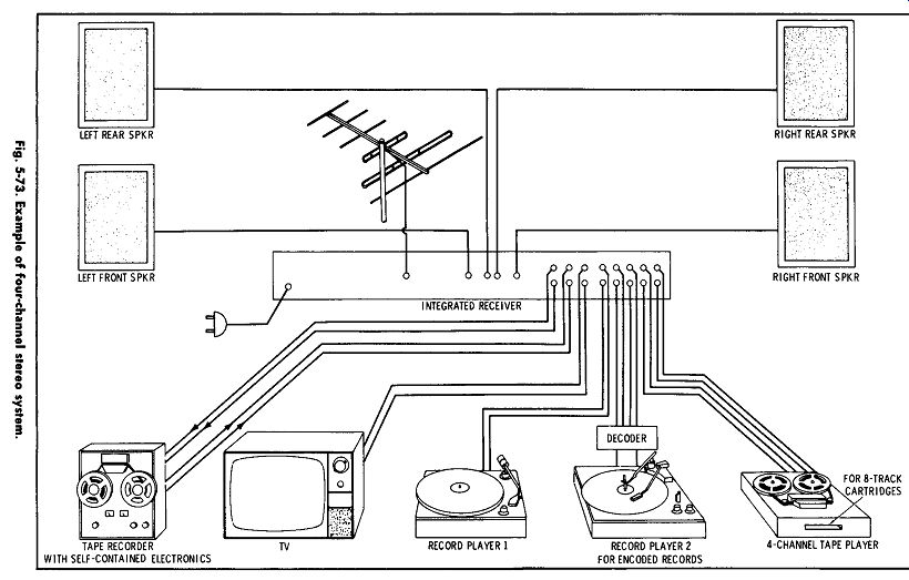
Fig. 5-73
------------
Courtesy Harman-Kardon, Inc.
(A) Harman-Kardon Festival 235.
Courtesy Matsushita Electric Corporation of America (C) Panasonic Model SC-8700. Courtesy AKAi America, Ltd.
(E) AKAi "true surround sound" package.
Courtesy JVC America, Inc.
(B) JVC Model 4450. Courtesy Sansui Electronics Corp.
(D) Sansui Model MQ-2000. Courtesy Fisher Radio (F) Fisher Model 40.
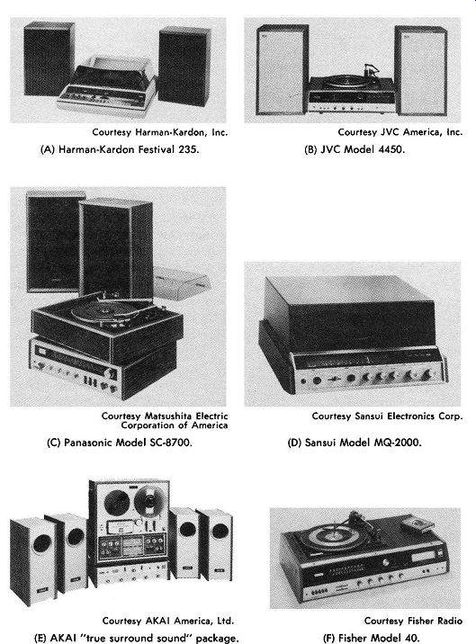
Fig. 5-74. Stereo package compacts.
----------
…facilities for phono, tape, tv, record, and playback inputs and outputs. Courtesy General Electric Co.
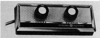
Fig. 5-75. Remote-control unit used with stereo preamplifier. Courtesy Fisher Radio
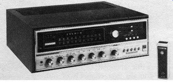
Fig. 5-76. Fisher four-channel receiver with wireless remote control of station selection.
Fig. 5-72 shows four-channel receivers with similar and advanced features. These units have provision for all kinds of inputs, outputs, monitoring, and control of the four channels. The unit in Fig. 5-72C comes with a built-in universal decoder that converts 4-2-4 pro grams directly through its own four channels. The receiver shown in Fig. 5-72D provides all of the foregoing features together with decoding and forms of program enhancement such as synthesizing.
Fig. 5-73 shows a system arrangement with many of the features that now can be included in a four-channel system package. The sample receiver shown will accept two phonos, one for standard records and one for encoded records such as the Columbia SQ records which contain four channels of information matrixed into two channels. The decoder shown between record player 2 and the receiver has two inputs and four outputs. If the Electro-Voice or Sansui units shown in Figs. 5-72C and 5-72D, respectively, are used and properly adjusted, the decoder is not necessary as it is built in.
Connections may have to be made to adapt to the phono, however.
The sample receiver shown in Fig. 5-73 provides for recording two-channel programs, storage, and replay. Television sound may be played over the system in mono to gain the benefit of the audio quality of a hi-fi reproduction system, which is generally superior to the average tv-set audio system. In addition, there is provision for two- and four-channel tape playback from both reels and cartridges.
The outputs to the speakers may be adjusted and balanced to suit the listener's taste and the room acoustics. All of the above features can be obtained at relatively low cost if sufficient study and time are given to the selection and installation of the system.
Fig. 5-74 shows several complete package compacts which will provide complete hi-fi two- or four-channel systems according to the desire of the user. Sometimes it is preferable to buy the compact separate from the speakers, as is possible with the units shown in Figs. 5-74D and 5-74F. In this manner it is possible to obtain equipment sized to fit the room requirements, quality to suit the taste, and prices to fit the pocketbook.
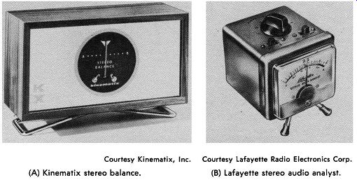
Courtesy Kinematix, Inc. Courtesy Lafayette Radio Electronics Corp.
(A) Kinematix stereo balance. (B) Lafayette stereo audio analyst.
Fig. 5-77. Typical stereo balance meters.
Many listeners like to be able to control volume and balance from the listening position, since this is the only place adjustment can be made for the proper effect. To provide for this need, manufacturers are making remote-control units available. A typical re mote-control unit is illustrated in Fig. 5-75. This unit has a 30-foot cable, the other end of which plugs into the tape input and output jacks of the preamplifier. Thus when the controls are set for the tape-record position, the outputs of the amplifier must pass through the cable to the remote-control unit and back to the preamplifier before passing on to the amplifier. In the process, the volume and balance may be controlled by the remote unit.
Other units available include radio-controlled station-selector and volume-control devices ( Fig. 5-76) that can be operated from any where in the room and which have no connecting wires. These devices do not enhance the quality, but they may come in handy for adjusting a four-speaker system, which has different effects for different listener positions and different positions of speaker placement. Such devices are also desirable for listeners who have difficulty in getting about.
Balance and Tuning Instruments
One of the functions important for the maintenance of good stereo effect is the preservation of balance in the system. If you have a preamplifier with volume-level meters, these meters can be used to check balance when a test tone is applied to both input channels at once. However, most systems do not have built-in meters. Therefore, an external metering device which will indicate when balance is achieved is useful. Two examples of commercially available balance meters are shown in Fig. 5-77. These meters can be attached to the outputs of the amplifiers and adjustments made until the meter needle is centered-indicating the two signals have exactly the same amplitude. It should be noted that this balancing is not normally done with the balance control; rather, fixed-setting adjustments ( screwdriver adjustments) are set for balanced output with the balance control in its center position. Then, the balance control can be adjusted later, during actual operation of the system, to compensate for such things as speaker types and placement, room acoustics, etc.
Courtesy McIntosh Laboratory Inc.
Fig. 5-78. McIntosh maximum performance indicator.
A common cause of distortion is multipath reception of the fm signal, which is caused by reflected signals from the same transmitter arriving at the receiving antenna slightly later than the direct signal. This can usually be corrected by antenna rotation or replacement. To check this condition, an indicator using a 3-inch cathode ray tube is available ( Fig. 5-78). This instrument also may be used to check signal strength and indicate correct tuning position more accurately than a meter; it will indicate the nature of the signal ( mono or stereo), the relative phase of the two channels, which channel is being used if only one is used, channel balance, and separation. For those who want the ultimate in fm stereo reception, this instrument is a valuable tool. There are receivers available with similar features built into one integral unit.