In our discussion to this point, we have considered cone-type radiators as though all the sound energy were released from the front of the cone. This is essentially what we meant in an earlier statement that direct-radiator speakers would be considered as being mounted in an infinite baffle. Now that we have considered the design features of speakers, we shall proceed to describe the effect of their accessory equipment.
BAFFLES
Actually, sound energy is released from both sides of a cone.
This is natural because there is air on both sides of the cone and the cone moves as a unit; however, when the cone moves forward, the air in front of it is compressed and the air in back of it is rarefied.
The sound released from the rear of the cone is of opposite phase to that released from the front of the cone. If the sound from the rear is allowed to flow so that it meets the sound from the front, cancellation takes place, and the response of the speaker drops off sharply. Such cancellation is substantial only when the paths to the meeting place are short compared to a wavelength and maximum when the total path length from the front of the cone to the back is exactly equal to zero or one wavelength. Sound waves from the rear change 360 degrees in phase in one wavelength and therefore oppose front waves. The wavelength of sound becomes longer as the frequency decreases; consequently, front-to-back interference is worst at the lowest frequencies and ordinarily marks the cutoff frequency of the speaker mounting. Such interference is not appreciable at higher frequencies at which the wavelength is small compared to the path length between the front and back of the cone. At these frequencies, the compressions and rarefactions are so closely spaced that there is no definite general cancellation action as at the low frequencies.
The longer the path length between front and rear, the lower is the frequency at which interference can take place. By extending the edges of the cone with some rigid flat material, we make it necessary for sound waves from the rear to travel out to the edges of the material before they can meet the sound waves from the front and interfere with them. The added material is called a baffle, and its principle is illustrated in Fig. 7-1. With the speaker alone ( Fig. 7-1A), the front and rear waves must travel only along one side of the cone to meet at the edge. This path is so short that a speaker alone without baffle will usually not reproduce much below about 350 Hz. In Fig. 7-1B is shown the situation when a baffle is added.
The length of the interference path is increased by the width of baffle material on each side. The reader can clearly demonstrate this effect by operating a speaker connected to a radio receiver or record player. First, listen to the speaker alone; then place it against a temporary, improvised baffle. The latter can be a large piece of cardboard or a corrugated carton with a hole cut in it. The increase of low-frequency response will be very clearly noticeable.
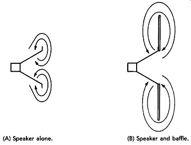
(A) Speaker alone. (B) Speaker and baffle.
Fig. 7-1. Increase of front-to-back interference path length by addition of baffle.
Baffles should be made of good sound-insulating material and should be soft enough to prevent rattle. Soft woods are satisfactory, but material like Celotex is more appropriate. The speaker must be securely fastened to the baffle, and the baffle must be rigidly mounted to prevent rattle.
If a baffle is to be of limited size, the speaker should not be mounted in the center. The center is a bad position because the path lengths to all four edges are the same, and the frequency components at which the path length ( one side) is one wavelength are severely attenuated. The center position is illustrated in Fig. 7-2A. If the speaker is moved toward one comer, as in Fig. 7-2B, the uniformity of response is much better because the path length to each edge is different, and the interference attenuation is distributed. The interference does not have to take place around the edge of the baffle but sometimes is purposely made to take place through a port, as illustrated in Fig. 7-2C. The design principle of such an arrangement is to equalize the response peak due to speaker resonance by the sharp attenuation around that frequency by spacing the port so that the sound travels a half wavelength. Some audiophiles adjust the size and shape of the port until it balances out the resonant peak of the speaker.
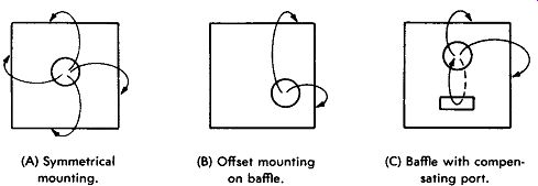
(A) Symmetrical mounting. (B) Offset mounting on baffle. (C) Baffle
with compensating port.
Fig. 7-2. Mounting a speaker on a flat baffle.
For a theoretically perfect speaker, the ideal baffle is one which has infinite lateral dimensions. The interference path lengths are then infinite, and no matter how low the frequencies of the sound components, cancellation or reinforcement due to baffle limitations cannot take place. Obviously, an infinite baffle in the fullest sense cannot be realized. However, if the baffle dimensions are sufficiently large that the frequency at which the path length is a half wave length is far below the range of frequencies to be used, the baffle is referred to as infinite. For example, a speaker mounted in a hole in the wall of a house and placed at least 6 feet from the nearest opening, with its back opening on one room and its front on the adjacent room or outside is, for all practical purposes, mounted on an infinite baffle. For use with an infinite baffle, one or two identical wide-range speakers with essentially Hat response over the desired frequency range are recommended to be placed at ear level or directed toward ear level. Speakers for this application should have very low resonance characteristics because there will be no provision for eliminating such defects. In the previous discussion of speakers, it was stated that each direct-radiator speaker was assumed to be mounted in an infinite baffle because this removes the effect of front-to-rear interference and allows us to consider the inherent effects of the speaker.
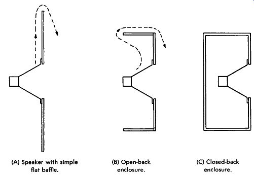
(A) Speaker with simple flat baffle. (B) Open-back enclosure. (C) Closed-back
enclosure.
Fig. 7-3. Evolution from a flat baffle to a simple enclosure.
SIMPLE ENCLOSURES
An infinite baffle, or an approximation of it, is one of the best speaker mountings. However, its size is a disadvantage in an ordinary home. For example, to reduce the frequency of interference to 50 Hz, the baffle must be at least 12 feet square! Because of this size problem, various arrangements have been developed in an attempt to get the same effect without the use of so much space.
This has led to the design of speaker enclosures.
The evolution from a Hat baffle to a simple enclosure is illustrated in Fig. 7-3. The simple Hat baffle is symbolized in Fig. 7-3A. To reduce the maximum dimension of the baffle, the outer portions can be bent back at the four edges to form an open box, as indicated in Fig. 7-3B. The path length is as great as for the Hat version, but the lateral dimensions are smaller. In Fig. 7-3C the process is carried one step further, and the back of the enclosure is closed; the back prevents any sound from the rear from getting to the front.
The open-back cabinet arrangement of Fig. 7-3B is the one commonly employed for radio and television receivers. A glance at the size of midget radio cabinets and a quick estimate of their path lengths will quickly show why low-frequency response is lacking in this type of receiver. The small speaker used is also a low-frequency limiting factor, but the cabinet is usually the important limitation. Large console models employ larger speakers and larger cabinets, but the path length is seldom sufficient to allow reproduction as low as 150 Hz, unless some special cabinet design other than the simple open-back box is used.
Another disadvantage of the open-back box is the fact that it acts as a resonant tube at some frequency well within the operating range, unless it is very large. Sounds of frequency near resonance are reproduced with annoyingly excessive volume relative to other sound components. Any sudden sound peaks of any frequency or sounds of low frequency can shock-excite the box into oscillation at the resonant frequency. Low-frequency sounds which are not attenuated by the interference path all seem to sound the same, because of shock excitation at the resonant frequency. This accounts for the fact that many console radio receivers and some of the earlier juke boxes emitted a constant booming during reproduction of music.
It would seem, then, that simply closing the box as in Fig. 7-3C would be the answer; and the box could be as small as desired as long as it holds the speaker, because the sides and back would block the rear-to-front interference path. Unfortunately, this is not so.
As soon as the box is closed up tight, as in Fig. 7-3C, the air in it is no longer free to move in the open as in the open-back cabinet.
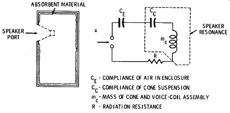
Fig. 7-4. Equivalent circuit of closed-box enclosure.
Instead, the action of the cone causes pressure changes in the cabinet rather than a combination of pressure and velocity. This means that the springiness or compliance of the air is an important factor. Compliance is acoustic capacitance and combines with the compliance of the cone suspension in such a way as to raise the resonant frequency of the system to a value higher than that of the speaker alone. The reason for this effect can be noted from the equivalent circuit for the closed box, given in Fig. 7-4. The mass ( inductive effect) of the cone, the compliance ( capacitive effect) of the cone suspension, and the compliance ( capacitive effect) of the air in the box are all effectively in series with each other. The smaller the box, the smaller is the acoustic capacitance it simulates.
Use of a small box lowers the capacitance connected in series with the series-resonant circuit of the speaker and thus raises the overall resonant frequency.
An important feature of the closed box is the fact that, because there is no motion of air in and out of it, there is no inertance or inductive effect. There is only compliance, or capacitive effect.
Accordingly, the box does not resonate itself as do some other types which we shall consider later. All it does is enter the resonant circuit of the speaker unit and raise the resonant frequency of the system above that of the speaker.
Compliance and thus the capacitive effect of a closed box in creases with size if the box can be made large enough so that the equivalent air compliance capacitance is large compared with the equivalent speaker-suspension compliance capacitance. Then the box will raise the resonant frequency only a negligible amount above the resonant frequency of the speaker. On the other hand, because the only effect of the box is to raise the resonant frequency, a speaker with a very low self-resonance could be put into a relatively small box. Then the system resonance would still be low enough for good results, even though it is raised above the resonant frequency of the speaker alone. Generally, a closed box of a given volume will raise the resonant frequency of the system a given percentage above the resonant frequency of the speaker.
Because the closed box keeps back radiation from getting around to the front and interfering, it is frequently referred to as the infinite-baffle enclosure and sometimes even as infinite baffle. As should be clear from the preceding discussion, this closed-box enclosure is not at all equivalent to a true infinite baffle unless it is so large that its effect on the resonant frequency is negligible.
Although the primary consideration in connection with a closed box is its effect on system resonance, this is not by any means the whole story. Conditions are such that as frequency increases above the resonance value, the system goes through a series of minor resonances which, if not counteracted, cause substantial irregularities in the response characteristic. There is also an effect due to reflection of back-radiated energy from the inside of the back and walls of the enclosure, with irregularities resulting from phase variations between cone vibrations and such reflected energy reaching the cone. These effects are minimized in practice by padding the inner surfaces of the cabinet walls with sound-absorbent material such as heavy felt, glass fiber, rock wool, or cellulose. This padding material acts as an acoustic resistance, lowering the Q of the box at high frequencies and tending to smooth out the response.
The baffle is a development of the foregoing, fitted with a system of screens which act as two-stage acoustic filters damping out cabinet and air resonances.
The compliance of the box increases with the size of the speaker cone. Therefore, the larger the cone, the greater is the percentage increase of speaker resonance caused by the enclosure. The resonant frequency of larger speakers is ordinarily so much lower than the resonant frequency of smaller speakers that the compliance increase is overcome, and the system resonance is lower with a larger speaker.
Practical designs are such as to limit the increase of resonance due to the cabinet to 20 percent over the speaker resonant frequency.
Authorities do not agree on any standard cabinet volume necessary for a given size of speaker, probably because of the wide variations of speaker resonance and suspension compliance in different models of speakers of the same cone size. Data from different sources specify that from 400 to 700 cubic inches of cabinet volume per inch of nominal speaker diameter should be used as a minimum. Since it is safer to stay on the large side, let us assume that 600 cubic inches per inch of nominal speaker diameter is a good minimum value.
On this basis, some typical speaker sizes and minimum required enclosure volumes would be as given in Table 7-1.
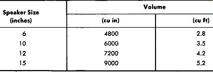
Table 7-1. Minimum Enclosure Volume for Typical Speakers
One significant design feature in many of these infinite-baffle types of enclosures is the breakup of the rear wall to minimize internal reflection effects which become severe at higher frequencies.
These breakup arrangements vary from two-surface double panels to complicated assemblies of small flat surfaces all at different angles.
Another method of minimizing these reflections is to make the whole rear portion of the enclosure semispherical, to break up reflections into an infinite number of angles. Representative of this type is the "kettledrum," which looks like the instrument after which it is named, with the speaker unit mounted in the diaphragm portion of the drum.
One manufacturer makes use of the infinite-baffle box but makes the rear wall with a flexible mounting to the remainder of the box.
This makes the cabinet give under sound-pressure waves, reducing the stiffness of the enclosure acoustically. The acoustic impedance of the box thus becomes equivalent to that of a much larger box. This enclosure is used with an extended-range, single-cone speaker to give excellent performance in a relatively small space.
In the infinite-baffle enclosure, all radiation from the rear of the speaker is eliminated. This minimizes interference but also makes systems of this type less efficient than others which utilize the sound from the rear.
One way to overcome this loss of efficiency is to use two or more identical speakers in the enclosure. When two or more speakers operate on the same audio-frequency signal and are mounted close to each other, they interact. Sound energy from one speaker rein forces the vibration of the cone of the other speaker, and vice versa, in what is known as mutual coupling. The action is similar to that in a multielement antenna array. The result is that the efficiency of the combination is much better than the efficiency of either speaker alone. Another advantage arises from the fact that even speakers of the same model are seldom exactly alike, because of tolerances in manufacture. These tolerances are actually an ad vantage because the difference in the resonant frequencies of the respective speakers tends to distribute the speaker resonance effect and make low-frequency response more uniform.
This idea is frequently used in infinite-baffle enclosures but is just as applicable to other types of enclosures. An example is given under the topic of bass-reflex enclosures.
BASS-REFLEX ENCLOSURES
The infinite flat baffle and the closed box eliminate back interference by isolating the rear of the cone from the front. In another, more popular arrangement, radiation from the rear of the cone is used to reinforce the front radiation rather than cancel it. This arrangement is illustrated in Fig. 7-5 and is known as the bass-reflex enclosure. It is the same as the closed box except that an opening is cut below the speaker. This opening, or port, allows air to flow in and out of the box as the speaker cone moves back and forth. The basic design principle is that the back radiation is fed through a path, including the box as a whole and the port, such that the back radiation emerges and reinforces radiation from the front.
Addition of the port adds acoustic inductance ( inertance) to the load offered to the speaker by the cabinet, because of the motion of air through the port. Although the stiffness of the air in the enclosure is not so great as in the closed box, it is still appreciable. The flow of air through the port is also accompanied by friction, which is an acoustic resistance effect. As illustrated in the equivalent circuit in Fig. 7-5, the port inertance, friction, and enclosure compliance form a parallel-resonant circuit. This circuit is connected effectively in series with the series-resonant circuit of the suspension and mass of the cone of the speaker.
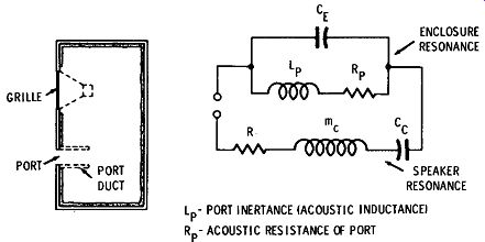
Fig. 7-5. The bass-reflex enclosure and its equivalent circuit.
Because of this more complex acoustic-impedance pattern, the design of a good bass-reflex enclosure involves a little more than simple path length. The effective length of the path of the sound from the rear of the cone is primarily dependent on the nature of the impedance offered by the enclosure itself, as expressed in the equivalent circuit. The design is simply a matter of keeping the resonant frequency of the enclosure in proper relation to the resonant frequency of the speaker. Because the enclosure offers parallel resonance, and the speaker series resonance, one of these resonances can be made to offset the other. Accordingly, one of the most popular methods of design places cabinet resonance right at the speaker resonance frequency. Others believe in making the enclosure resonate slightly lower in frequency than the speaker, feeling that, although this does not completely compensate for speaker resonance, it extends the overall response to a lower frequency.
Placing cabinet resonance exactly at the speaker resonant frequency does not eliminate the bump in frequency response due to speaker resonance, unless the Q's of the two resonant systems are approximately equalized. Such equalization is accomplished by loading the enclosure with acoustic resistance until the overall response is smoothest. Acoustic resistance is supplied by absorbent material on the inner walls but more efficiently by placing grille cloth or other mesh-like material over the port. When air is forced through small holes, friction, which is acoustic resistance, is developed.
The port cannot be placed too close to the speaker because then the path from the rear of the cone starts to become direct, like that in a small flat baffle, rather than including the impedance of the box as a whole, as it should. To keep the overall cabinet size to a mini mum, some designs add a duct in back of the port, as shown by the dash lines in Fig. 7-5. This allows maintenance of a minimum direct path length from the rear even for relatively small spacing between the port and the speaker and keeps down the overall volume. There is a limit to volume reduction by this method because, as the port becomes larger, the effective volume of the cabinet ( which must not include port-duct volume) becomes smaller inside. Also, the end of the port duct must not come too close to the rear wall of the enclosure and should not exceed one-tenth of a wavelength at the resonant frequency.
The cabinet resonance is determined by the well-known Helmholtz resonator equation:
t=2010"4 where,
f is the resonant frequency of the cabinet, in hertz,
A is the area of the port, in square inches,
V is the volume of the cabinet, in cubic inches.
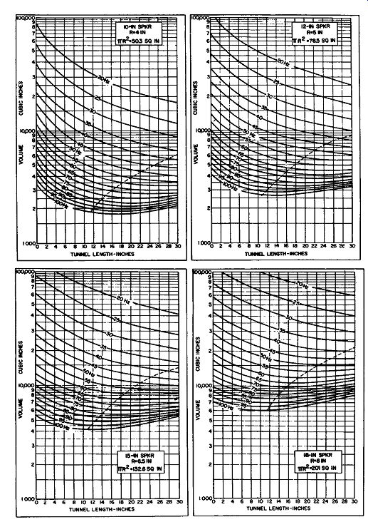
Fig. 7-6. Design graphs for bass-reflex cabinets.
Calculations of the design parameters of the bass-reflex enclosure are beyond the scope of this guide, and our approach has been to explain which factors are important and why. Dimensional information has been carefully worked out and put into graphical form, an example of which is shown in Fig. 7-6. The cabinet volume must have a definite value and should not be as large as possible, as occurs with the flat baffle and the closed box.
Because of variations in speakers and tolerances in cabinet construction, the actual cabinet and speaker resonant frequencies seldom coincide exactly, even though designed to do so. Because the area of the port influences the cabinet resonant frequency, this area may be varied after construction and assembly are complete, to trim the cabinet resonance to match that of the speaker. The port can be covered in part by a book or other flat, rigid device, and the open area can be varied.
An audio-frequency signal generator ( audio oscillator) of reasonably constant output is useful in checking for proper port-area adjustment. The front of the speaker cone mounted in the enclosure is watched as the generator output frequency is passed through frequencies from 30 Hz upward. As the resonant frequency of the speaker is reached, cone excursion increases greatly to a maximum and subsides to smaller deflections at higher frequencies. The audio signal is adjusted for resonance. Then the port area is varied until cone excursion becomes minimum. The speaker resonance is then being damped by cabinet anti-resonance.
Because the bass-reflex enclosure reverses the phase of the back radiation and makes it additive to the front radiation at low frequencies, it is often referred to as an acoustic phase inverter.
Some designers prefer to make the bass-reflex type of enclosure with distributed ports. Instead of one port of calculated size, a number of smaller ports are used. The areas of these ports add up to the proper calculated port area. It is claimed that the different positions of the different holes prevent dips in the response curve at frequencies at which the interference path length becomes one wavelength.
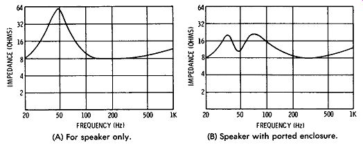
(A) For speaker only. (B) Speaker with ported enclosure.
Fig. 7-7. Speaker impedance versus frequency.
The effect of the bass-reflex type of enclosure in damping the response peak of speaker resonance is illustrated in Fig. 7-7.
Sometimes more than one woofer or tweeter unit is used in a bass-reflex cabinet to take advantage of mutual-coupling efficiency.
An example of a small bass-reflex enclosure employing two 6-inch woofers and a tweeter is shown in Fig. 7-8.
ACOUSTIC LABYRINTH
Another method of acoustic phase inversion is exemplified by the acoustic labyrinth, depicted in Fig. 7-9. The cabinet is divided into parts by a series of baffles in such a way that the spaces between the baffles form a lengthened passage, or duct, of approximately constant cross section between the back of the speaker and the front of the cabinet. The labyrinth thus feeds the back radiation around to the front.
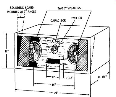
Fig. 7-8
Besides the acoustic inversion effect, the labyrinth has another very important design consideration. The pipe or tube simulated by the space between the baffles acts as a tuned line when it is exactly a quarter-wavelength long at the resonant frequency of the speaker.
It simulates a parallel-resonant circuit which equalizes the series resonance of the speaker unit in the same manner as in the bass reflex cabinet. The labyrinth has two main beneficial actions: ( 1) It equalizes the resonant bump in the speaker response and spreads out low-frequency response, and ( 2) it provides reinforcement of the sound in the range near the frequency at which the duct length is a half-wavelength ( twice the resonant frequency of the speaker). Fig. 7-9. An acoustic-labyrinth cabinet arrangement.
HORN-TYPE ENCLOSURES
Audio engineers have always been attracted to horns because of their high efficiency and good frequency response above cutoff frequency; but, as was brought out in our previous basic discussion of horns, a conventional horn structure for a low enough cutoff frequency for high fidelity ( say 50 Hz or lower) is so large at the mouth as to be prohibitive for ordinary use. To overcome this problem, a number of designs have been developed to simulate the performance of a large horn without the large dimensions necessary in the conventional type. In home installation, the use of horn-type enclosures is confined to the low-frequency range, and they are ordinarily employed in conjunction with a separate tweeter ( which may itself have a separate horn), or they are driven by a coaxial or extended-range, single-cone driver. In the home, cone-type drivers are almost universally used to drive the horns at low frequencies.
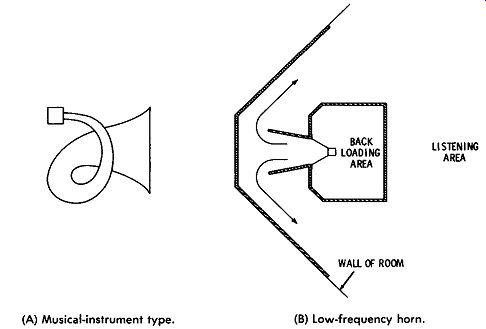
Fig. 7-10. Folded horns. (A) Musical-instrument type. (B) Low-frequency
horn.
One of the first measures taken to reduce size is the folding of the horn. Folded or rolled exponential horns have been used for centuries in musical instruments, and these look like that shown in Fig. 7-10A. Of course, this type has a small throat and in electrical sound systems would be used with a diaphragm-type driver. In high-fidelity systems, horns are driven by cone-type speakers ( for low frequencies) and must therefore have large throat diameters.
A low-frequency horn application more typical of high-fidelity equipment is shown in Fig. 7-10B. The front of the cone faces away from the listener, but its output is directed around between the baffles toward the listening area. The baffles are so constructed and mounted that the closed area leading from the speaker cone to the room roughly approximates an exponential horn of the low-frequency cutoff desired. This type of horn in practical design cannot in itself have the full mouth area necessary for theoretical cutoff in the desired range of approximately 50 Hz. The structure is normally designed to be placed in the corner of a room, and the walls of the room become continuations of the sides of the horn, as illustrated.
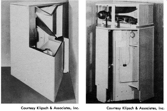
Fig. 7-12. Cutaway view of Klipschorn woofer horn. Courtesy Klipsch & Associates,
Inc.
Fig. 7-13. Rear view of Klipschorn with tweeter on top. Courtesy Klipsch & Associates, Inc.
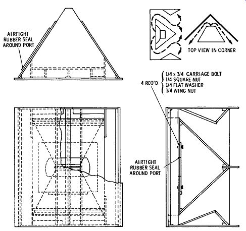
Fig. 7-11. Klipschorn arrangement used in Electro-Voice assemblage.
Notice the back-loading area in the structure of Fig. 7-10B. This is considered necessary for cone drivers because without it the loading on the cone is not symmetrical, and distortion results. This is why in practically all low-frequency horn structures some balanced loading is provided. The back loading is not always a closed area, but in some cases constitutes slots or ports.
One of the best known of the better reproducing systems is the Klipschorn arrangement. A layout of the interior of a typical commercial type of the Klipschorn is illustrated in the diagrams of Fig. 7-11. The principle is the same as that of Fig. 7-l0B. A cutaway view of the original Klipschorn is shown in Fig. 7-12. An enclosure in the center of the cabinet back-loads the woofer. The front of the woofer cone opens into a narrow front channel, which is the throat of the horn. From there, the woofer output is led around the center enclosure through ducts of a gradually increasing cross-sectional area. These ducts open out to the back of the cabinet. A vertical baffle at the back leads the sound to emanate from the sides through vertical openings between the baffle and the remainder of the cabinet. The sides of the cabinet are at such an angle with respect to the walls that the space between them and the walls forms a continuation of the horn. As the sound waves pass the front of the cabinet, they are still enclosed in the continuation of the horn formed by the walls in the comer of the room. A cutaway view of the low-frequency horn and the complete system, with tweeter horn mounted on the top, is shown in Fig. 7-13. Another horn-enclosure arrangement utilizing a labyrinth back-loading is shown in Fig. 7-14.
The Empire speaker with acoustical suspension and adjustments (Fig. 7-15A) has the following features ( Fig. 7-15B ):
1. A 12-inch mass-loaded woofer with floating (acoustical) suspension, a 4-inch voice coil, and a large ( 18 lbs) speaker ceramic structure.
2. Sound-absorbent rear loading.
3. Die-cast mid-frequency /high-frequency full-dispersion acoustic lens.
4. Imported marble top.
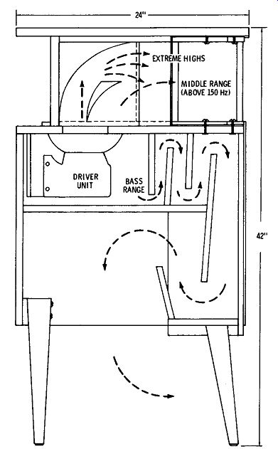
Fig. 7-14. Cross section of acoustic-labyrinth horn.
5. Ultrasonic domed tweeter.
6. Full-presence midrange direct radiator.
7. Totally damped acoustic fiber enclosure.
8. Exclusive dynamic reflex stop system for enriched bass response; can be adjusted to suit room acoustics.
9. Front-loaded horn with 360-degree-aperture throat.
10. Terminals concealed underneath.
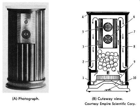
(A) Photograph. (B) Cutaway view.
Fig. 7-15. The Empire Grenadier 800P speaker. Courtesy Empire Scientific Corp.
COMPACT Hi-Fi SPEAKER SYSTEMS
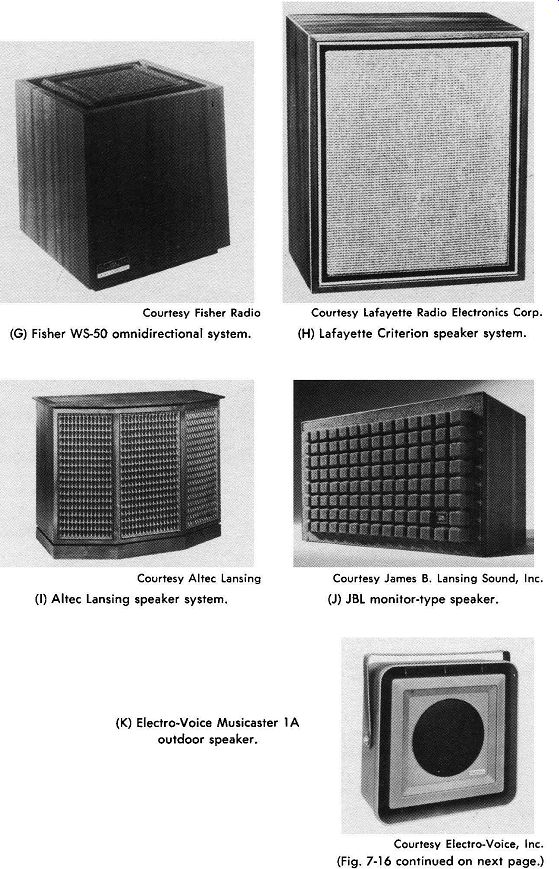
Compact high-fidelity speaker systems in decorator cabinets suit able for placing on a bookshelf or use as end tables, consolettes, or other decorative pieces are now designed and made to reproduce as accurately as any other type of system available-and at reduced prices over larger systems. These systems reproduce accurately from 40 to 20,000 Hz and can be purchased in the price range of $50 to $1000. See Figs. 7-16A through 7-16Q. Exponents of larger speakers and systems point out that low bass response requires movement of large amounts of air and therefore hi-fi reproduction requires a large speaker cone. However, new designs and materials and the application of the natural laws of physics have made possible the movement of larger amounts of air with multiple speakers with small cones by the use of loose mountings ( in acoustical suspension) allowing greater lateral movement, and by adding to the effective mass of the moving material. The increased travel of the cone moves the same amount of air as a larger cone with normal travel, and it provides more accurate control and reproduction. The latter is accomplished by the use of heavier and stronger magnets.
Acoustical suspension is provided by the reduction of forces on the cone at the mounting ring by the use of soft materials such as polyvinyl chloride (PVC) painstakingly applied to provide greater stretch with dynamic concentric alignment and negligible resistance to wide lateral movement. The force necessary to damp the movement of the cone is provided by the elastic air sealed inside the enclosure; thus it is said that the cone is in acoustical suspension or suspended on pressurized air and the elastic mount.
In these designs, the compression and decompression operate in a nearly linear manner, reducing much of the distortion inherent in larger speaker designs. In addition, tweeters and midrange reproducers have been improved in quality and width of dispersion, creating overall improvements that widen the utility and application of lower-cost high-fidelity systems.
For output measurements of Acoustic Research speaker AR-3, see Fig. 7-17. In this figure, the response curves of each radiator are shown separately so that interference patterns--which reflect the particular position of the recording microphone rather than reproducing quality-are eliminated. The speaker provides level controls for independent adjustment of the midrange unit and the super tweeter section.
The speaker system shown in Fig. 7-18 is a small unit containing nine small ( 4-inch) speakers, all producing the full audio range.
There are no crossovers, and therefore no distortion or loss is introduced on this count. The speakers are long-excursion, high-compliance (acoustic-suspension) speakers that can move large amounts of air. By acting in unison ( mutual coupling of speakers), the group provides the same effect as one larger speaker with a cone area approaching the sum of the cone areas of the nine speakers. In addition, an electrical equalizer ( Fig. 7-18C) is used to compensate for loss of bass response and to adjust overall performance to suit the room and the listener's taste.
------------------
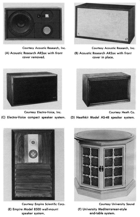
Courtesy Acoustic Research, Inc.
(A) Acoustic Research AR2ax with front cover removed. Courtesy Electro-Voice, Inc.
(C) Electro-Voice compact speaker system. Courtesy Empire Scientific Corp.
(E) Empire Model 8500 wall-mount speaker system. Courtesy Acoustic Research, Inc.
(B) Acoustic Research AR2ax with front cover in place. Courtesy Heath Co.
(D) Heathkit Model AS-48 speaker system. Courtesy University Sound
(F) University Mediterranean-style end-table system. Courtesy Fisher Radio
(G) Fisher WS-50 omnidirectional system. Courtesy Altec Lansing
(I) Altec Lansing speaker system. Courtesy Lafayette Radio Electronics Corp.
(H) Lafayette Criterion speaker system. Courtesy James B. Lansing Sound, Inc.
(J) JBL monitor-type speaker.
(K) Electro-Voice Musicaster 1 A outdoor speaker. Courtesy Electro-Voice, Inc.
Fig. 7-16. Compact speaker systems.
-------------------
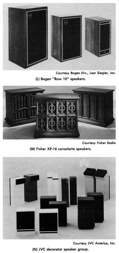
Courtesy Bogen Div., Lear Siegler, Inc.
(L) Bogen "Row l O" speakers. Courtesy Fisher Radio
(M) Fisher XP-16 consolette speakers. Courtesy JVC America, Inc.
(N) JVC decorator speaker group. Courtesy Bose Corp.
(O) Bose 501 speaker system. Courtesy McIntosh Laboratory Inc .
(P) McIntosh speaker system. Courtesy Electro-Voice, Inc.
(Q) Electro-Voice consolette speaker.
Fig. 7-16. Compact speaker systems (Cont).
-------------------
(A) Woofer frequency response. (B) Midrange response in test baffle. (C) Super-tweeter response in test baffle. (D) Woofer harmonic distortion.
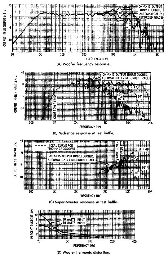
Fig. 7-17. Output characteristics of Acoustic Research AR-3 speaker.
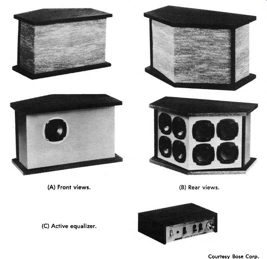
(A) Front views. (B) Rear views . (C) Active equalizer. Courtesy Bose Corp.
Fig. 7-18. Bose 901 Direct/Reflecting speaker system.
The advantages of this system are:
(1) The response of each speaker in the group is different from that of each of the others, causing the resonant frequency of each speaker to be different from that of every other speaker; therefore the resonance of each speaker is minute when compared to the output of the acoustically coupled group operating in unison. As a result, individual resonances and other distortions are negligible in comparison to the total output.
(2) The speaker enclosure is pentagonal in shape, thus avoiding standing-wave resonance. There are no sides parallel to any baffle on which any of the nine speakers are mounted.
(3) The omni directional effect of the speakers is increased by placement of speakers so that only 11 percent of the sound ( one speaker) is direct-radiated toward the listener and 89 percent ( eight speakers) of the sound is toward the rear to provide reflected sound in all directions from the wall back into the room. This provides more uniform dispersion at high frequencies throughout the room.
(4) An equalizer is part of the system; it provides accurate compensation for the bass rolloff in acoustic-suspension speakers, and for the effects of radiation impedances, speaker characteristics, enclosure dimensions-and even for the grille cloth effects. There is negligible distortion introduced by this unit. The equalization is provided in the system before the amplifier, thereby eliminating bulky components and providing greater accuracy.
ELECTRICAL SPEAKER EQUALIZERS
Electrical equalizers for compact speakers are now available for use instead of mechanical baffles and horns to compensate for bass response rolloff, and to provide for variation of effective bass power output requirements due to location of a speaker in a room and other room audio characteristics. ( Examples of these units are shown in Figs. 7-18C, 7-20, and 7-21.)
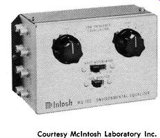
Fig. 7-20. McIntosh MQ 102 environmental equalizer. Courtesy McIntosh
Laboratory Inc.
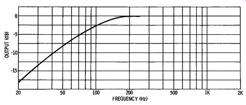
Fig. 7-19. Reduction in bass response in acoustic-suspension speakers.
The equalizer is primarily designed to compensate for the rapid falloff of bass output that occurs in high-quality acoustic-suspension (air-spring) compact speakers. In compact acoustical-suspension speakers without horn enclosures and / or other mechanical reinforcement, additional power is required to provide the large amounts of air movement necessary to produce a proper reproduction of base notes below 200 hertz. The baffle and horn can provide the needed reinforcement in larger units. The bass output of the acoustical-suspension speaker drops off as shown in Fig. 7-19. This sharp drop-off of response is within the short range of 20 to 200 hertz.
Most preamplifier sections of modem hi-fi systems do not provide for compensation of this large drop-off in such a short span of frequencies. If the bass boost in the average preamp ( which usually has a fixed slope from 20 to 1000 instead of 20 to 200 Hz) is used to increase the bass response to compensate for the rolloff in the speaker, this boost will increase the response in a different proportion (slope) than is required, thereby introducing more distortion.
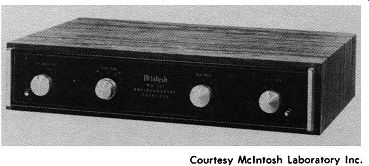
The equalizer shown in Fig. 7-20 is specifically designed to provide compensation for bass rolloff of acoustical-suspension speakers. Another advantage of this equalizer is in compensating for room effects on the bass output of the speaker system in any particular configuration that may be used. The room in which a loudspeaker system is placed can substantially alter its sound balance. An equalizer may be designed to compensate for room conditions and for different positions of a speaker in any room.
Fig. 7-21 shows an equalizer that provides bass correction plus compensation for variations in speaker output requirements due to speaker placement or other factors. The power output of a bass speaker varies over an 8 to 1 range ( 9 dB) depending on where the speaker is placed in the room (Fig. 7-22). For example, if a speaker is suspended in the center of a large sound-absorbing room, a 20 hertz signal will radiate equally in all directions from the speaker.
It will be radiating into a sphere. If the speaker is lowered to the floor in the center of the room, it will be radiating into a hemisphere.
The signal striking the floor would be reflected upward and in effect would almost double the loudness. If the speaker is then moved along the floor to the center of a wall, the power will double again. The speaker is now radiating into a quarter of a sphere.
However, if you move the speaker into the corner of the room, the radiation is concentrated into one eighth of a sphere, and the power doubles again to 8 times the power of the first position.
Courtesy McIntosh laboratory Inc.
Fig. 7-21. McIntosh MQ 101 environmental equalizer.
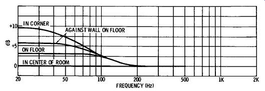
Fig. 7-22. Effects of room gain for different speaker placements.
(A) Equalizer correction. (B) Speaker and equalizer.
Fig. 7-23. Response curves for McIntosh equalizer.
(A) Treble-level switch in normal position. (B) Treble-level switch in decrease position.
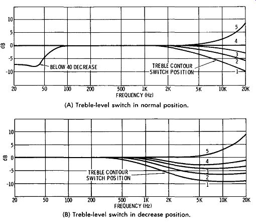
Fig. 7-24. Response curves for Bose equalizer.
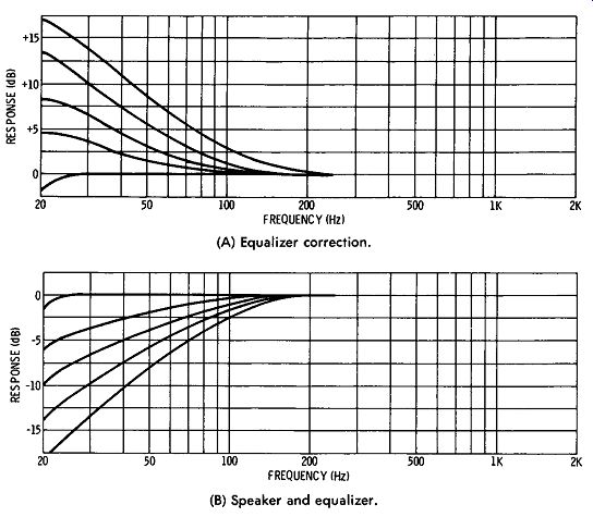
To restore the system to a flat response under any of these conditions, while preserving the nearly perfect transient response of certain acoustic-suspension speakers, the electrical equalizer shown in Fig. 7-21 may be adjusted to provide a signal having a curve equal but opposite to the reduction or increase that occurs as a result of relocating the speaker. The equalizer can be adjusted to provide for room equalization for any location or condition of the room.
In the unit shown in Fig. 7-20, the electrical correction can be varied in accordance with the curves shown in Fig. 7-23. Provision is made in the unit shown in Fig. 7-21 for adjustment of low-frequency correction as shown in Fig. 7-23 and mid-frequency and high-frequency differences in rooms. Some rooms are heavily draped and furnished. A room of this sort needs mid-frequency and treble boost to make music sound naturally alive. Other rooms have smooth, hard walls or concrete :floors, and mid-frequency and treble attenuation is required to restore music-hall balance and effect.
In the unit shown in Fig. 7-18, the active equalizer offers the choice of 19 additional contours that can be selected from the front panel. This gives the listener flexibility to exercise his own taste in compensating for room and other variables. Various contours avail able with this unit are shown in Fig. 7-24.
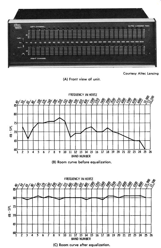
The Altec Acousta-Voicette stereo equalizer shown in Fig. 7-25A is designed to adjust the stereo system output to the room coupling so that a flat acoustical response at the listener's position is allowed, as shown in Figs 7-25B and 7-25C. This device can correct the usual narrow-band room acoustic faults by adjustment of two sets ( for stereo operation) of 24 filters spaced at center-frequency intervals of½ octave from 63 Hz to 12.5 kHz. There is a broadband insertion control on each channel. Tape monitor, equalizer in, and equalizer out switching also is provided.
This unit can minimize room resonances and increase spatial perception by increasing the levels at high threshold areas for those with hearing deficiencies. It can provide for tuning the stereo system to the room to any listener's taste.
(A) Front view of unit. (B) Room curve before equalization. (C) Room
curve after equalization.
Fig. 7-25. Altec Acousta-Voicette stereo equalizer.
STEREO SPEAKER SYSTEMS
The basic design principles of speaker enclosures are the same for stereo as for monophonic reproduction. However, the fact that two or more sound reproducing sources must be used in stereo has led to variations in how these enclosures are arranged.
The simplest approach is two or more complete reproducing systems, one to handle the left signal and one for the right signal, and possibly two more for left-rear and right-rear signals. Stereo speaker-enclosure systems have evolved along the lines indicated by the arrangements illustrated in block form in Fig. 7-26. Many arrangements take advantage of the fact that the stereo effect is obtained predominantly with higher-frequency components of the sound, because at low frequencies the wavelength is so great that phase differences and depth distinctions between spaced objects are small. There is no definite frequency at which transition takes place, but there is a gradual change effect. Authorities place the dividing line for practical purposes between 150 Hz and 400 Hz.
Frequency components in this range and below may come from a single source since little stereo effect can be produced under normal conditions.
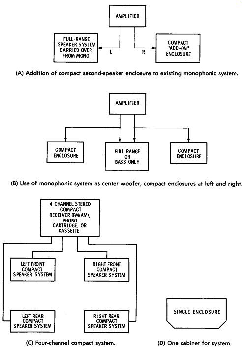
In Fig. 7-26A, the existing system has been expanded by the addition of a limited-range ( not much low-frequency response) compact enclosure to the full-range system previously used for monophonic reproduction. The added speaker provides all but the lowest frequency components and serves as the right-channel speaker for the stereo effect. The full-range system provides the left stereo speaker and reproduces all of the lowest-frequency non directional components.
Two compact wide-range enclosures and a low-frequency center speaker are illustrated in Fig. 7-26B. The center reproducer need only be a woofer, responsive to frequencies up to 500 Hz. A dual voice-coil speaker, like that shown in Fig. 6-35, would be a logical choice for the center speaker. However, if the system is being evolved from a former mono system, the center speaker could be the full-range reproducer from that system.
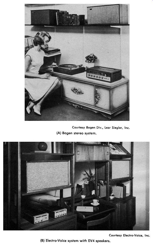
The advent of stereo stimulated the trend toward smaller en closures. Therefore, special techniques have been developed to re duce the size and price of full low-frequency response units. A number of compact single-channel reproducers have been developed with excellent characteristics for arrangements like those of Figs. 7-26A and 7-26B. They are available in all finishes and styles. Some are floor models; others are placed on a bookshelf or table. Some contain single speakers and have response £rpm about 50 Hz up, so they can be used with a center woofer with no low-frequency loss; others are full-range arrangements, with claimed frequency response extending from 40 to 20,000 Hz. The latter could be used without center speaker, to provide left and right sources for a two-source arrangement. Most of the compact enclosures do not exceed 2 feet in their maximum dimension. Typical complete arrangements using compact enclosures are shown in Fig. 7-27.
(A) Addition of compact second-speaker enclosure to existing monophonic
system. (B) Use of monophonic system as center woofer, compact enclosures
at left and right. (C) Four-channel compact system. (D) One cabinet for
system.
Fig. 7-26. Enclosure arrangements for stereo.
There are still a large number of people who would prefer to have the complete stereo system enclosed in one cabinet to simplify furniture arrangement. Because the separation between left and right reproducers must be at least 5 feet (effectively), this means that the cabinet must be either 5 feet long or must have some arrangement by which the sound can be projected so as to simulate the proper spacing. Two examples of single-cabinet stereo-system reproducer enclosures are shown in Fig. 7-28.
A very elaborate stereo reproducing system is pictured in Fig. 7-29. The design of the reproducer is illustrated in Fig. 7-30. Basically it consists of two three-way ( woofer, midrange, and tweeter)
speaker systems, one mounted on each side of the enclosure structure. Their sound outputs are directed against a large round surface which reflects them to the listening area in such a way as to distribute the sound while maintaining its essential directivity for stereo effect.
Stereo Headphones
A good pair of stereo headphones is a worthwhile accessory to any high-quality music system. An increasing number of amplifiers and receivers include a stereo-headphone jack on their front panels, and, if no jack is available, connection to the speaker terminals is a simple matter. If a tape recorder is part of the music system, any serious attempt at live recording, as well as sound-on-sound recording techniques, requires headphone monitoring for proper balance and level adjustment.
A type of headset suitable for home listening is shown in Fig. 7-31.
Each earpiece contains a 1-inch miniature dynamic speaker and is filled with plastic foam for resonance damping. The front of the driver cone is also loaded with plastic foam, and its enclosed rear is vented to the interior of the earpiece through two small holes. These design features are intended to give a wide, smooth frequency response with a minimum of peaks and holes.
The liquid-filled vinyl cushions mold themselves firmly but gently around the wearer's ear. External sounds are almost totally excluded, and it is said that the padded headband and soft ear cushions permit the listener to wear the headphones for hours without experiencing discomfort or fatigue.
The 8-foot plastic-covered cord has four conductors so that the two earphones can be electrically isolated if desired. They are fitted with a three-circuit phone plug that fits the. stereo phone jacks of most amplifiers.
The frequency response of the phones shown in Fig. 7-31 is rated at 30 to 20,000 Hz. While stereo headphones provide a very different listening impression than do speakers, earphones have a wide-range response, smooth and with low distortion. High-frequency hiss is somewhat noticeable. Fig. 7-32 shows a record changer and built-in amplifier that is specifically designed for headset listening.
(A) Bogen stereo system. (B) Electro-Voice system with EV4 speakers.
(C) Heathkit stereo center. (D) NuTone system with in-wall speakers.
Fig. 7-27. Examples of use of compact enclosures.
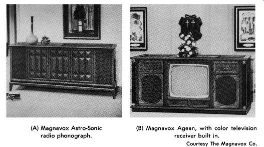
(A) Magnavox Astra-Sonic radio phonograph. (B) Magnavox Agean, with
color television receiver built in.
Fig. 7-28. Single-cabinet stereo systems.
CHOOSING A SPEAKER SYSTEM
The judgment of speaker-system performance is, to a great extent, subjective. A number of system designs with excellent characteristics are available. Differences in the performance of these systems is such that the listener's taste rather than known measurable technical factors provides the basis of a choice. This is partly because the listener does not always conform to the ideal of wanting reproduction exactly like that which he would hear when present at the location of the performance. Various factors have conditioned him to tend to like a few deviations from realism, although constant experience with reproduction that is nearly perfect can educate one.
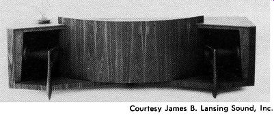
Courtesy James B. Lansing Sound, Inc.
Fig. 7-29. A full-range stereo horn enclosure.
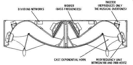
Fig. 7-30. Speaker arrangement in the enclosure of Fig. 7-29.
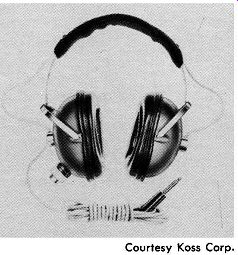
Fig. 7-31. Koss professional stereo phones.
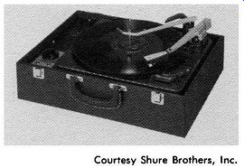
Fig. 7-32. Shure SA-10 record changer and amplifier for headset stereo
listening.
There are a few people who just do not have a hearing system adequate to hear more than a limited degree of the audio range and who, either physically or by training, cannot distinguish be tween the performance of a poor radio receiver and that of a well designed high-fidelity system. Then there are all the gradations in between. Keeping these facts in mind, we can note the following points in the selection of a high-fidelity speaker system.
1. There is no set formula for high quality, for reasons already explained. Each type of well-known system has its enthusiastic sup porters, but the best audio engineers recognize both the strength and weakness of each system. Although they may favor one over the others for themselves, they realize that the type of listener and his situation influence things greatly. You cannot find the best system offhand; you must figure it out for yourself.
2. You cannot separate the choice of the speaker from the choice of the system as a whole. When you first decide you want high fidelity, you must also decide the optimum compromise between your ear and the cost. Optimum high fidelity costs money. Speakers cost the most of any part of it. The speaker system is thus very likely where the limit of cost will enter the choice. The first thing to do is determine the highest quality which really means something to you.
The only way to do this is to shop around. Visit the stores where systems are sold, and, even better, become acquainted with people who have high-fidelity systems of various degrees of quality and different types of arrangements, and see which ones you like. More important, determine where you stop appreciating increments of increase in quality per unit of cost.
A vast majority of people are very happy with a system having response only to about 6 or 8 kHz, providing other distortions are low. A limit can almost be defined in terms of dollars because performance generally follows cost to some degree, assuming that parts of the system are properly matched. Once you have made your choice of quality level, the specifications of your whole system including input devices, preamplifier, as well as the speaker system, should be chosen to match. This is important because two of the easiest ways to waste money are: (1) to have major parts of a system not matched in performance and cost requirements, and (2) to pay the high cost of quality increments above your natural taste requirements.
3. Frequency-range limitation is not as annoying as other forms of distortion. When we speak of the response of a component or system, we assume ( and thus probably take too much for granted) that the harmonic and intermodulation distortion over the entire range are low. It should be kept in mind that a limited frequency range in itself minimizes harmonic distortion because it cuts off components of harmonic frequencies above the range. Listener tests in general have definitely shown that a good, clean, low-distortion frequency response up to 4000 Hz is preferable to a frequency response that extends up to 10,000 or 15,000 Hz, but with slightly greater harmonic distortion. The prospective purchaser of a speaker system should, therefore, not place too much emphasis on nominal claims of frequency response but should assure himself as to how low all forms of distortion remain over the entire range.
4. The listener's ear is the final test. All specifications, charts, and data should be considered in their relationship to the sound to the listener's ear, rather than to any technical tests; however, data from a valid technical test may be criteria as to whether the listener may some day acquire a more discriminating taste.
5. Although there is much to be said for the wide range of some of the single-cone, extended-range systems, the systems with the greatest range are generally those of the multiple type. The purchase of a multiple system does not in itself guarantee high fidelity.
Such things as divided presence ( consciousness of dual source locations), takeover, and fuzzy highs are common complaints. Many feel that a dual system is worthwhile in a higher-priced system but that the single-cone type of system is appropriate for lower-cost installations.
6. In separate-unit multiple systems, watch the phasing. The path length between the listener's ear and the source should be the same for both woofer and tweeter. If this requirement is not adhered to, the high- and low-frequency components join in the wrong phase relationship at many frequencies, and substantial distortion can result.
SPEAKER LISTENING TESTS
As has been explained, the final test of a speaker system is how it sounds. The listener who does not know what to look for in such tests is at a disadvantage. He may overlook factors which later, after he has purchased the system, may assume new importance. Experience has shown that proper attention to certain features will go a long way toward assuring continued satisfaction.
There are no standards of performance. Furthermore, most prospective purchasers of speaker systems do not have equipment to make the tests necessary to check a system against proper standards.
Consequently, listener tests must be made as personal comparisons between different available systems.
The following suggestions should tell the reader what to look for in making listener tests on a speaker system. Each feature should be compared from one system to the next in an attempt to evaluate the one most pleasing. In any tests, every effort should be made to eliminate other components of the whole high-fidelity equipment by using the same or similar auxiliary equipment with each different speaker system. If the reader has not had experience in distinguishing between audio-frequency tones of different frequencies, it is suggested that he obtain an audio signal generator or test record made for this purpose, connect it to a speaker, and run through the audio range, familiarizing himself with the sound of audio tones of low, middle-range, and high frequencies. He will then be better prepared for the listening tests which follow.
1. Look for distinctions between various kinds of bass notes, such as those from different musical instruments. If a bass drum, plucked strings, or bass horn all sound alike, then there is probably excessive bass resonance effect in the speaker or the enclosure.
2. Compare performance on voice with performance on music.
Voices should be crisp, natural, and highly intelligible with the same amplifier adjustments used for music from the same source.
3. Listen for sudden crescendos of percussion instruments and to pizzicato passages of music. Check for evidences of hangover transient distortion which would make it difficult to distinguish one pluck from another.
4. If possible, apply to the system a high-frequency tone of, let us say, about 10,000 Hz. If this is not possible, listen to needle scratching or interstation noise from an fm tuner. Then walk around in front of the reproducer, checking relative output directivity. The broader the output distribution at high frequency, the better is the system.
5. Tap the sides of the enclosure with your knuckles and note whether they are deadened properly or respond with undesirable vibration. All parts of an enclosure structure should be solid and dead.
6. Be sure that, for each speaker system checked, the amplifier boost controls are adjusted for the most pleasing performance. Also check the speaker balance control ( if any) for best balance between woofer and tweeter output. This control is sometimes referred to as the treble adjustment of the speaker system. It is unfair to compare systems in which all controls are not adjusted for optimum performance.