The assembly of a number of components to create a complete sound system is not difficult if some general principles of system design are observed. The major units which make up a sound system are record players, tuners, tape equipment, microphones, television receivers, preamplifiers, amplifiers, speakers, enclosures, baffles, horns, and other acoustical aids. Other parts, such as switching circuits, pads, microphone and speaker stands, cabling, and the like are also to be planned. In order to assemble a sound system which will perform in a desired manner, it is necessary to be familiar with all the components used, and what is required of each of them.
REQUIREMENTS
The most important physical and electrical design characteristics of a complete sound system involve size, power, fidelity, gain, compensation, filtering, number and type of controls, number and type of input (program) sources, and number and type of speakers. The design objective and limiting factors are elements which determine these characteristics. Each must be carefully considered before the components of a sound system can be specified. All of the components which make up a complete system must be carefully co ordinated if the system is to operate properly. No component should be chosen without regard to the other parts of the system with which it is to be used.
AUDIO POWER
Before the components of a system can be selected, the power necessary to supply the required sound volume must be determined.
The absolute unit of power measurement, as applied to physical sound, is the acoustic watt. The acoustic watt is a unit of power of the physical activity of air at sound frequencies. It is not convenient to think in terms of the acoustic watt when designing a sound system, because the actual requirements are related to too many variables and the net results are extremely difficult to measure.
The objective is to provide the listener with a close approximation to an original live performance. Achievement of this objective re quires the subjective equivalents of sound pressure levels that approach those of a concert hall. Although the peak sound pressure level of a live performance is about 100 dB, the average listener prefers to operate an audio system at a peak sound pressure level of about 80 dB. The amplifier, however, should also accommodate listeners who desire higher-than-average levels, perhaps to peaks of 100 dB. A sound pressure level of 100 dB corresponds to less than one watt of acoustic power for an average room of about 3000 cubic feet.
If speaker efficiencies are considered to be in the order of 5 percent, a stereophonic amplifier, then, must be capable of delivering about 20 watts per channel. Higher power outputs are required for speakers of lower efficiency. The peak-to-average level for most program material is between 20 and 23 dB ( 100 dB peak less 80 dB average equals 20 dB peak-to-average). A system capable of providing a continuous level of 77 dB and peaks of 100 dB would satisfy the power requirements of nearly all listeners. Moreover, because sustained passages that are as much as 10 dB above the average may occur, the power-output capability of a top-caliber system should not be below the value required for a peak of 100 dB of acoustic power while delivering a continuous level of 87 dB of acoustic power.
The audio watt is more convenient to work with than the acoustic watt. The audio watt referred to in this respect is the unit of electrical power at audio frequencies as measured at the output terminals of an amplifier. The power requirement of a specific installation can be expressed in terms of the number of watts of audio power required from the amplifier to be used if the efficiency of the speaker system is taken into consideration.
The efficiency of good speakers used with sound systems runs from under 5 to over 15 percent. Assuming that the speakers used have an average efficiency of 5 percent, it is possible to estimate the power requirements of a particular installation in terms of watts of audio power.
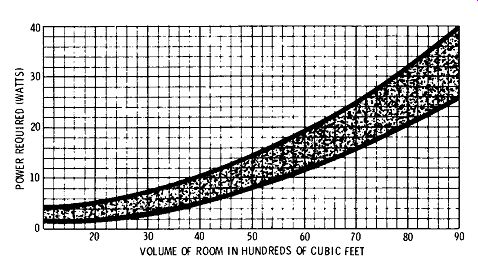
Fig. 8-1 is a chart that can be used for rough estimating. It shows
the minimum power required for coverage of rooms of various sizes.
The size of a room is based on its volume in cubic feet.

Fig. 8-1. Audio power required for various room sizes.
The shaded area indicates the approximate limits within which the power requirements fall. The range of selection is given to provide for various possible uses of the system. The wider the range of reproduction required, the greater is the power required.
The charts shown in Figs. 8-1 and 8-2 are based on use of efficient speakers with reinforced baffling. However, designers of speakers of the acoustic-suspension type, now commonly used in home hi-fi installations, generally trade off efficiency of speaker output for improved quality and reduction in size; the efficiency of such speakers may be as low as one percent. Therefore, when these charts are used to determine the optimum power requirements of acoustic suspension speakers, it is recommended that the power requirements be multiplied by a factor of five.
Since a proportionate increase in power capability of an amplifier to drive a less efficient speaker is less expensive than the cost of a more efficient speaker of equal quality, the trade-off described above is usually in the best interest of the consumer.
Determining Power Required
The exact audio power required from the amplifier used with an indoor installation is governed by several factors. The most important of these are: the volume of the room or rooms to be served; the acoustic characteristics of the walls, ceiling, and floor; the average noise level prevailing; the frequency range of the system and of the material to be reproduced; and the efficiency of the speaker system.
The chart of Fig. 8-2 can be used to estimate detailed power requirements for rooms of various volumes. Curve A is for speech reinforcement systems using high-efficiency horn-type speakers when the prevailing noise level is low. If the noise level is high, curve B applies, providing horn-type speakers are used. Curve B also applies when cone speakers are used and the noise level is low. When the noise level is high and cone speakers are used, curve C applies.
Curve C should also be used for the average music reproducing system when the noise level is low. For very high-quality, wide range reproduction, curve D should be used.
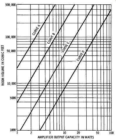
fig. 8-2. Amplifier output required for indoor applications.
The curves of Fig. 8-3 give the amplifier power capacity for out door reproduction. The power required for outdoor installation depends on the distance between the speakers and the farthest point to be covered. Curve A is for a system using a single horn-type speaker covering an angle of 30 degrees. Curve B is for a system covering an angle of 60 degrees, and curve C is for a system covering an angle of 90 degrees.
In multiple-room installations, i.e., installations where several areas are to be served, it is necessary to determine the total power requirements of all the locations which are to be equipped with speakers, and then arrange the distribution of power to the various speakers in accordance with the requirements of the individual locations.
For top-quality installations, there are two reasons why it is advisable to select an amplifier with a higher wattage rating than is actually required. One reason is that the higher-power-rated amplifiers with the same ratings in regard to distortion and frequency ...
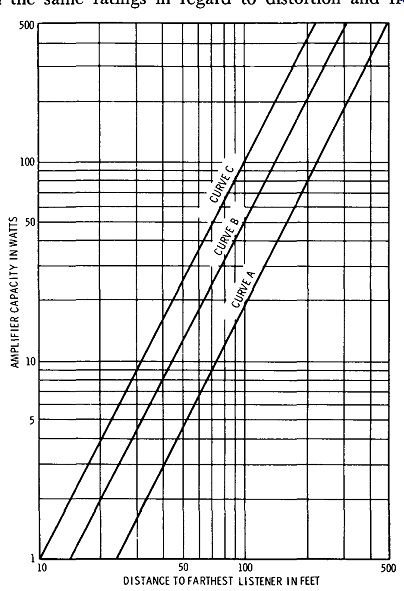
Fig. 8-3. Amplifier output required for outdoor applications.
... response as the lower-power amplifiers will provide better operating characteristics at lower-power operation than the lower-rated units.
The other reason is that greater dynamic range is available to handle extra loud crescendos, which may occasionally drive a smaller amplifier beyond its rated output, thereby causing noticeable distortion.
FIDELITY
The term "fidelity" includes a number of considerations. By definition, fidelity is the degree with which a system accurately reproduces without distortion at its output the essential characteristics of the signal that is impressed on its input. The fidelity requirements of a system depend largely on the type of material which is to be produced and on the listener's taste.
Frequency response is an important characteristic which helps to determine the fidelity of a system. Frequency response is a rating which indicates the range over which a system reproduces all frequencies uniformly; thus, a system may be said to have a flat response between 30 and 20,000 Hz, meaning that a curve of its output plotted against frequency is flat from 30 to 20,000 Hz. The term "flat" is generally understood to mean a deviation of less than ±0.5 dB, which is not noticeable to the average human hearing system.
Although human hearing is limited to about 20,000 Hz at best, modem equipment is often rated up to 100,000 Hz. The implication and fact is that if an amplifier has X distortion at a higher-than audible range, it should be able to produce less than X distortion at audible frequencies. The same principle is applied as that applied to the linear operation of class-A amplifiers: the smaller the operating portion of the overall response curve used the more nearly distortion-free the operation will be.
FREQUENCY REQUIREMENTS
For systems used predominantly for music, the frequency response should extend at least from 30 to 15,000 Hz. When a system is used for a direct pickup, and optimum fidelity is desired, a frequency response of from 30 to 20,000 Hz is desirable. This means that if the sound to be reproduced is being picked up directly from an orchestra or a singer, a wide range should be used. If, however, the source of sound is from recordings or electrical transcriptions, there is no necessity for an extremely wide range. A frequency response of from 30 to 15,000 Hz is adequate for such a system. This takes into consideration the average ear and all available components in the hi-fi chain.
Both the upper and lower limits of the frequency response of a system are important. It has been conclusively determined through subjective tests that the upper and lower limits are related, and that when the upper limit is raised, the lower limit should be lowered. It is a fairly well established rule of thumb among audio engineers that the product of the upper and lower frequency limits should be about 640,000 Hz^2. This means that if the upper limit is 10,000 Hz, the lower limit should be 640,000 / 10,000, or 64 Hz. When the upper limit is 20,000 Hz, the lower limit should be around 32 Hz. The center point of the audible sound range is usually regarded as 800 Hz ( 800^2 = 640,000).
For best results, the response of a system should be the same number of octaves above 800 Hz as it is below. ( An octave is the difference between two tones whose frequencies are related by a factor of 2. For example, one octave below 800 Hz is 800 + 2, or 400 Hz. One octave above 800 Hz is 1600 Hz.) The wider the frequency response of a sound reinforcement system, the more important it is to keep distortion content to the lowest possible percentage. Distortion can completely negate the advantage of a wide frequency-response characteristic.
If a sound installation is to be used for a-m radio reproduction, or if other limited-response programs ( confined to frequencies between 100 and 8000 Hz) are to be used, designing a system whose upper limit is 8000 Hz and whose lower limit is 100 Hz will reduce to a considerable extent the power and response requirements without reducing the efficiency of the system. When it has been determined that a system is to be used for limited response only and reproduction of highest-fidelity components is not considered worth maximum investment, the system components should be selected so as to have a narrow frequency-response range throughout. This will save considerable money, and modem limited-range equipment will still sound good.
DISTORTION
Fidelity also includes the distortion characteristics of a system.
For systems of the highest quality, the total cumulative distortion as fed to the speaker should not exceed 1 percent at normal operating level.
Distortion refers to the presence of components in the output which were not in the input, but were generated in the system itself, and which may be in the form of changes in waveshape or new components harmonically related to the input frequencies. For a detailed description of distortion see Section 1. If the equipment were to be used for speech reinforcement only, distortion content up to 3 percent might not be objectionable, and the highest frequency needed to be reproduced would be limited to approximately 7000 Hz. Overall system harmonic distortion becomes increasingly un pleasant to the ears as the upper frequency limit is raised.
GAIN
The overall gain of the amplifier parts of a system is important and must be carefully considered. The total gain of the amplifiers must be sufficient to drive the final stages to full output with the lowest-level input to be used. Gain is measured in decibels, or dB. A decibel is an expression of a ratio of power or a ratio of voltage; thus, if we know the input signal voltage ( Ei) of a preamplifier and the output voltage ( E0 ) of the same preamplifier, the overall gain requirements of this unit may be determined by using the following expression: Gain ( in dB) = 20 log ( i:) + 10 log ( :~:J where Z_in and Z_out are the input and output impedances, respectively.
If the input power ( P,) and the output power ( PO ) are known, the gain may be determined by the following formula: Gain (in dB) = 10 log(~:) As a matter of convenience, specifications of hi-fi preamplifiers and amplifiers are usually given in overall ratings in a more practical manner. Specifications for basic amplifiers are described as a certain voltage input across a definite input load impedance necessary to produce full output according to power-output rating. Standard input requirements for basic amplifiers may vary from ½ volt to 3 volts of input across input load impedances varying from 100 to 500 kilohms.
Voltage input specifications must always be related to the load.
A preamplifier or tuner rated to deliver 1 volt across 100,000 ohms will not drive a basic amplifier requiring 1 volt across 250,000 ohms to full output without more than rated preamplifier distortion. In some cases, input load conditions of basic amplifiers are not given, and ample drive should be provided to cover all contingencies. Also, basic amplifiers should have less than 2500-pf input capacitance to avoid distortion in the coupling network.
Preamplifiers are usually rated in dB of gain or input voltage level for full output. Fifty to sixty dB of gain will usually provide sufficient output ( 5 volts or more) across standard input impedances from the lowest-level program sources, such as dynamic phono cartridges or microphones. Outputs from these sources may be as low as 5 millivolts across 170 ohms. Input devices having lower outputs than this fall out of the practical application range, as noise becomes too great a factor.
If all units are rated in dB, decibels may be added or subtracted; an amplifier always adds a certain number of dB, and an attenuator subtracts a certain number of dB. Thus, if a preamplifier with a gain of 50 dB is used with a power amplifier with a gain of 60 dB, the total gain will be 50 + 60, or 110 dB. The term "dBm" is used to indicate the volume level of a constant tone. It means that the level, or sound volume, of a constant tone is the specified number of dB above 1 milliwatt. These units are used in specifications of professional equipment and apply only to micro phone levels as far as high fidelity is concerned.
The volume unit is another term commonly encountered in the use of pickup units. The volume unit is similar to the dBm in that it is used to indicate the level of a signal in dB above or below 1 milli watt. The volume unit indicates that the measurement was made on average program material rather than on a constant tone as does the dBm. The volume unit is abbreviated VU.
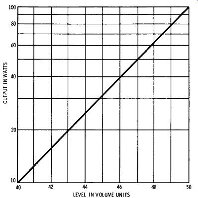
Fig. 8-4. Power versus volume units.
After the power output which will be required from the amplifier has been determined, and the microphones and other input sources have been selected, the gain which will be required from the amplifier can be determined. The first step in determining the gain is to find the volume level in VU to which the power output of the amplifier corresponds. The curve in Fig. 8-4 gives a number of typical values of output power and the volume levels in VU to which they correspond.
It is then necessary to determine the output level of the lowest level microphone to be used. Since microphones are rated in a number of different ways, their ratings should be converted to dB below 1 mW/ 1 bar, as described in Section 4. The output level of microphones is usually a number of dB below 1 mW. Therefore, the output level must be added to the power output of the amplifier ( in VU) to obtain the gain in dB required from the amplifier.
The following is an example of the procedure followed: Assume that the power required from the amplifier is 15 watts, which is equivalent to +42 VU ( Fig. 8-4). If the microphone to be used with the amplifier has an output level of 53 dB below 1 mW, the gain required from the amplifier in this installation would be 42 + 53, or 95 dB. In practice, it is usually wise to add a safety factor of about 10 percent. In the preceding case, it would bring the gain required to 105 dB. If an amplifier is to be used with a number of input sources, the gain required for use with each microphone should be deter mined.
If high-fidelity recording of one's own program material is de sired, gain becomes an important factor. Since the average basic amplifier provides only a 40- to 75-dB gain, a preamplifier to cover all conditions of input and output combinations should provide for a distortionless gain of 70 dB or more. Many preamplifiers are rated at only 50 to 60 dB of gain; so, if hi-fi recording is a must, one must either obtain a basic amplifier with sufficient gain to add to the preamplifier gain to provide a total of more than 100, or one must obtain a preamplifier with more gain.
These high gains are required only for high-fidelity microphone pickup. Ordinary magnetic or crystal pickups for phono or microphone applications require less than 100 dB of total gain for up to 60 watts full output. Under all conditions, 100 dB of total gain is recommended for average applications, barring the lowest-output hi-fi microphones, because it is easier and therefore less costly to produce high-quality low-gain amplifiers and preamplifiers.
BUILDING UP A HIGH-FIDELITY SYSTEM
Some of us may be fortunate enough to be able to go "all out" for high fidelity with our first system, but most of us cannot. In fact, the reader should not feel discouraged if his budget is limited, because he will probably learn more and derive greater enjoyment from building up his system in stages, starting with something relatively modest. Let us consider now some typical systems and also how an elaborate system can be evolved from a simpler one.
First, consider the simple breakdown illustrated by the block diagram of Fig. 8-5. It is convenient to think of a system as broken down into its three main parts: ( 1) a program source device, such as a record player or tuner, ( 2) an amplifier and controls, and ( 3) a speaker system. This arrangement is a minimum complement for either monophonic or stereophonic reproduction. The differences in stereo are only that provision must be made for a minimum of two channels ( possibly four channels) and their related controls in the amplifier section, and that two or more speaker systems must be used. In addition, the source material must provide stereo signal outputs.
If you are starting from scratch, you should keep in mind that you will eventually want a stereo system. No modern high-fidelity system can be complete without stereo. However, we must consider here the possibility that you have a monophonic system now that is "left over" from pre-stereo days, or that you are starting from scratch and want to keep cost down in the first stage by limiting the system to mono. However, in either case, with a little careful planning, the monophonic system can be integrated into a stereo system later.

Fig. 8-5. Three main parts of a high-fidelity system.
There is one part of the high-fidelity system in which you can save by starting with mono, with no compromise in future use for stereo; that is the speaker system. A good wide-range speaker system will cost from $50 to $750, and of course you can spend considerably more. You will need to double this cost for two-channel stereo. If the rest of your system is designed for stereo, you can buy one speaker system first and operate with monophonic reproduction until you can afford the other speaker.
Actually, the cost of amplifiers, changers, and tuners is not much greater for stereo than for mono, if you insist on good high-fidelity reproduction. For example, a good stereo record player can be bought for approximately $75, and buying a record player of equal quality for monophonic reproduction will not save you anything.
A good stereo amplifier, with two complete channels and all the controls you need, is not more than 30 percent higher in cost than a similar monophonic type.
At this point, individual needs must be analyzed-balanced design applied in relation to price and quality. The greatest attention should be given to the speaker. Fifty or one-hundred dollars more invested in this unit will give many times more return than the same amount spent in the amplifier. The next important unit where most return will be had per extra dollar spent is in the record player.
Even a few dollars may make a great difference in this unit. Amplifiers are now so well developed that even the lower-cost combined units perform well. There is little noticeable difference in amplifiers until you double or triple the investment, and then the difference is small, compared with the differences between the lower- and higher cost speakers.
Enclosures cannot be selected from a technical standpoint alone, as they must be selected to suit the overall room layout and associated furnishing of a room. In relation to investment, it is again recommended that emphasis should be placed on the speaker rather than the enclosure. A good speaker will sound good in a poor en closure, but a poor speaker will still sound poor in a good enclosure.
Furthermore, a good speaker will sound good with any reasonable bailing arrangement.
Fig. 8-5 shows a minimum-complexity arrangement which can still produce continuous-program hi-fi reproduction of excellent quality. With a record changer as the program source, this arrangement will be entirely suitable for playing medium-fidelity records and also give excellent performance on hi-fi records. Substituting a tuner ( either a-m, fm, or both) provides another starter arrangement, designed for radio reception. If the tuner has high output, and if volume and compensation controls are provided in the tuner, only a basic amplifier need be provided. If the tuner does not possess a high output, then the preamplifier-amplifier unit will be required for equalization and volume control.
A good starter arrangement is given in the block diagram of Fig. 8-6A. When you purchase the speaker, you should keep in mind that you will want to add another speaker later, to provide for stereo reproduction. Therefore, the first speaker system might be something in a small enclosure, so that when the other speaker system is added the total space taken up will not be excessive.
The next step in the evolution is to add the second speaker system, as illustrated in Fig. 8-6B. Now, with this one addition, you have stereo performance, using the stereo record player and amplifier.
The next logical addition is a tuner, so you can hear stereo broad casts ( Fig. 8-6C). Your stereo amplifier should have inputs for both the record player and tuner, and a selector to choose either. You are now ready either to play records or listen to stereo broadcasts.
Perhaps you prefer a tape machine to either the record player or tuner; it can be purchased in place of either one, or in addition to them.
The diagram in Fig. 8-6C exemplifies a fairly complete stereo system, but you can still build from there. Fig. 8-7 illustrates a more advanced system. Here, the preamplifier is separate and is used with a basic amplifier unit. Record-player, tuner, and tape input devices are used. A third, "middle," speaker has been added, to minimize "hole-in-the-middle" effects. The same third-speaker circuit can be used to supply remote speakers. However, it should be noted that going from an integrated amplifier-control unit to a preamplifier and basic amplifier is a major change in system design because many of the control facilities of the original complete amplifier are duplicated in the preamplifier. The original integrated amplifier could still be used, but it might be economically desirable to replace it with a basic amplifier. The separate preamplifier will normally provide much greater flexibility than the original integrated amplifier.
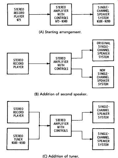
(A) Starting arrangement. (B) Addition of second speaker (C) Addition
of tuner.
Fig. 8-6. Steps in acquiring a hi-fi system.
This system does not provide for control of the center channel because its origin in this arrangement is at the final output point of the other two channels. Control of the center channel is essential to true stereo effect. An arrangement that provides complete control of center-channel blending and volume is shown in Fig. 8-8. This particular arrangement utilizes a combination stereo preamplifier and power amplifier, with center-channel mixing controls and a low-level center-channel output. The center-channel output is fed to a separate single-channel amplifier which drives the center speaker. An additional feature of this arrangement is that an old single-channel amplifier may be utilized for the center channel; thus the stereo effect can be improved at low cost. The two-channel stereo power output is fed to the left and right speakers in the same manner as shown in previous arrangements. There are numerous combinations of preamplifier and control center or preamplifier, power amplifier, and control center that provide a low-level third channel output that may be used in this arrangement.
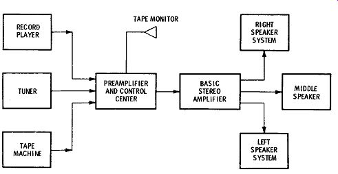
Fig. 8-7. An advanced stereo system.
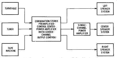
Fig. 8-8. Three-speaker output with controlled middle channel.
FOUR-CHANNEL SYSTEMS
Four discrete channels and four speakers may be used to provide a four-directional surround-sound effect that is quite different from two-channel, two- or three-speaker stereo. The operational difference is that four instead of two different signals are fed to four separate speaker systems, and the speakers are placed in various ways that, in effect, surround the listener to provide a concert-hall effect that can be quite dramatic compared with regular two-channel stereo.
There are three main techniques commonly in use to provide four-channel sound. They are operation with four discrete channels ( sometimes called 4-4-4), the derived-sound technique ( 2-2-4), and the encoded matrix ( 4-2-4) technique. All of these systems are described from several points of view elsewhere in this guide. The general theory of derived sound, four-discrete-channel operation, and matrixing operations is discussed in Section 2. Descriptions of available equipment to adapt for and/ or provide four-channel sound are contained in Sections 4 and 5.
Discrete Four-Channel Tape System ( 4-4-4)
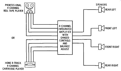
Fig. 8-9. System for playback of four discrete channels from tape.
The optimum method of providing four-channel sound is shown in Fig. 8-9. Signals from four-channel tape, either reel or cartridge, are played back through a four-channel integrated amplifier which contains four separate preamplifier-amplifier circuits with ganged controls and provision for balancing of all the channels. This arrangement is known as four-discrete-channel stereo ( 4-4-4). The equipment and tape in this system should maintain 30 to 40 dB of separation between channels and provide any degree of control and balance necessary to bring out the best of any four-channel material.
Four-channel open-reel equipment is expensive, and program material is scarce. This equipment is most suitable for professional use in developing program material in the studios. However, eight track, four-channel cartridge tapes are available in fairly good supply, and excellent equipment is available, in the middle price range, that contains Dolbyized circuits and provision for use of chromium-dioxide tape that extends the useful audio range to provide excellent four-channel hi-fi sound for the home or car.
Derived Four-Channel System ( 2-2-4)
The simplest and lowest-cost method of creating the four-channel surround-sound effect is with the use of adapters and equipment for the derived-sound technique. This system fully utilizes the capacities of present two-channel systems by extracting parts of the signal content from the output power of a two-channel system and re directing selected portions of these signals to two additional speakers ( Fig. 8-10) . This system obtains the additional channels of related but partially discrete information by means of a sum-and difference extraction matrix to provide two additional signals from the power outputs of a two-channel stereo amplifier. A simplified connection diagram of the Dynaco Quadaptor is shown in Fig. 8-11.
When the original two output signals are fed through the matrix, the center front speaker is connected in series with the ground returns from the left and right speakers. The amplifier must have 6 dB of blending to maintain sufficient separation at the speakers.
The 6 dB of blending is equal in amplitude and opposite in polarity to the cross talk which is introduced by the front-speaker connection, and therefore cancels out the cross talk and provides excellent separation of the speaker outputs.
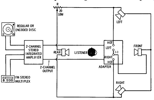
Fig. 8-10. Use of two-channel equipment with adapter to derive two additional
channels.
The rear speaker is connected from the hot terminal of the left amplifier to the hot terminal of the right amplifier. No connection is made from the rear speaker to a ground terminal. The speaker impedance isolates the hot sides of the amplifier outputs, and the common or ground terminals in each stereo-channel output should be connected.
Derived-sound adapters may be used with nearly all component stereo amplifiers and receivers. A very few amplifiers ( notably those with a "floating" output circuit) cannot be used with this arrangement. The reason is that this system requires a common ground reference between the two channels. Any restrictions against joining the common (ground) output terminals of a stereo amplifier or receiver should be pointed out in its instruction manual. This limitation is not related to the normal prohibition against paralleling the outputs of a transistor amplifier ( direct connections between the "hot" or "high" terminals of the left and right channels). If separate mono amplifiers are used, they should have similar circuits so that proper phase relationships are maintained between the two channels. It may be desirable to connect their ground terminals together.
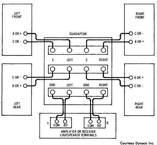
Fig. 8-11. Simplified connection diagram for Dynaco Quadaptor.
When more speakers are added in the same room, the amplifier power requirements do not necessarily increase, provided that the sum of the power outputs of the two amplifiers exceeds the sum of the minimum power-input requirements of all speakers in the room; see Figs. 8-1, 8-2, and 8-3.
Fig. 5-60C shows the Dynaco SCA-80Q, which is a two-channel stereo preamp-amplifier with the Dynaquad circuits and controls built in and connected internally. This unit accepts two-channel in put and provides properly phased and balanced derived-four-channel output. The input can be from standard two-channel stereo fm multiplex, disc, or tape. The advantage of the Dynaco system is its simplicity; only a standard stereo system with two additional speakers ( making a total of four speakers) and the Quadaptor circuitry are needed.
The operation of the Quadaptor ( shown in Figs. 5-60A and 5-60B) is as follows: The REAR LEVEL control simultaneously adjusts the volume level of the two rear speakers. It does not affect the loud ness of the front speakers. In the fully clockwise position, with four similar speakers, the rear-speaker level is the same for a rear signal source as is the front-speaker level for a front source. Because the listener will normally be seated closer to the rear speakers, this control provides attenuation as recommended ( usually 3 to 7 dB). The control will likely be used at or near the ¾-clockwise position with four similar speakers.
The mode switch, a 3-position switch, provides derived "four dimensional" sound in its normally centered position. In the lower position, the rear speakers are disconnected, and the front speakers are heard in conventional two-channel stereo. If it is desired to use another, remote pair of 8- or 16-ohm speakers simultaneously with some speakers in the main listening area, it is recommended that the Front Only switch position be used to protect the amplifier from undue loading. This will provide conventional stereo sound in both areas.
In the upper (spring-return) Balance Check position, the speakers are connected to reproduce only the difference between the channels. Here, there will be no output from a monophonic source ( where both channels are identical) . To adjust for proper operation, this system must be balanced.
The REAR LEVEL control is set to the maximum clockwise position, and the mode switch to Front Only. The desired stereo program is played at the normally used volume level. The amplifier or receiver should be switched to a monophonic operation mode, so that identical signals are appearing at the left and right amplifier outputs.
This is usually identified as "Mono," "A + B," or "L + R" on the amplifier controls. If the amplifier has no mono switch provisions, a mono record or an a-m or mono fm radio program may be used instead.
When the Quadaptor switch is in the Balance Check position, little or no sound will be heard from any of the speakers. To obtain precise electrical balance and maximum separation, the balance control of the amplifier should be adjusted slowly for a null, or minimum sound output. If the amplifier has individual volume controls on each channel rather than separate volume and balance controls, the two volume controls must be adjusted for the null.
If the amplifier provides independent left- and right-channel bass and treble controls, the two bass controls should be nulled, as well as the two treble controls. Normally this will be in their "flat" positions, or where the tone controls are not affecting the circuit. If it is preferred to have some tonal modification, the controls should be nulled with the amount of boost or cut which the listener normally employs.
Once a null has been established, release the Quadaptor switch, return the amplifier mode to normal stereo, and you should be listening to four-dimensional sound. Adjust the REAR LEVEL control so that the back speakers are just perceptible in the normal listening position.
This simple balancing procedure may be repeated whenever changes in the volume-control setting on the amplifier or differing program sources make it advisable.
Because the balance-control setting is critical to obtain optimum separation in this system, this control should not be used for shifting left-to-right emphasis when listening in the four-channel mode.
Thus the listener is advised to shift his position to adjust balance inequities.
If there is reduced separation, lowered output level, and uncertain centering of soloists, or an ill-defined null, the cause is most likely to be reversed polarity (phase) in one of the connections to the Quadaptor.
The degree of increased realism which this derived system provides over conventional two-channel stereo varies with the program material. Some material is specially recorded to take advantage of the capabilities of this system. With existing two-channel material, the benefits to be derived are largely random and depend on the particular recording techniques employed. However, such benefits may be dramatic on some recordings, and it is a rare performance which does not show some improvement.
When the Quadaptor switch is placed in the Front Only position and then switched to four channels, additional audience-participation sound, including applause, should become apparent. In pop material, certain instrumentalists may appear to be located behind the listener, the result of unintentional microphone mis-phasing.
Organ works frequently reveal added low-end power. On many classical recordings, the initial impression when switching from two to four channels may not seem so dramatic.
The benefits of four-dimensional sound will often be most apparent in smaller rooms, where space restrictions were previously a significant handicap in reproducing material such as organ-pedal fundamentals, or in creating any sense of "hall sound." It should not be expected to hear four separate and distinct channels from the use of derived-sound techniques, as this would be in essence discrete four-channel sound or encoded four-channel sound. Realistic musical reproduction with derived sound will contain a similarity in relationship between all sound channels and significant overlap between them, and a large percentage of the program material will be included in common in all channels. The derived four-channel system attempts to take advantage of this principle to develop the full simulated reproduction of the two sound channels and of their phase and amplitude interrelation ships in the four-channel mode. In effect, more information has always been on the record or tape than has been separated previously due to the masking effect of the louder signals ( described elsewhere in this guide). Recording engineers have long striven to find microphone-pickup techniques and performer placement in the studio or hall which could uncover more of the "flavor" of the live performance on playback.
The derived system provides for standard stereo reproduction from the front speakers without use of the rear speakers. If you switch off the rear speakers, you should hear the same left-to-right separation you always had. If a soloist was recorded in a central location, blended into the two channels, the solo will come from a virtual front center location between the front speakers. A mono phonic program played through the derived system using only two speakers will also appear as a centered front source.
In operation, it is generally advisable to reduce the level of the rear-speaker output with a series resistor ( R in Fig. 8-10). This could be a 20-ohm, 10-watt variable noninductive resistor. The rear speaker may give better results if it is raised to a level above the head of the listener and pointed directly at the listener.
Encoded Matrix Four-Channel System ( 4-2-4)
The 4-2-4 encoded matrix technique offers a compromise method that provides discrete four-channel stereo sound with sufficient separation to develop concert-hall realism, and at the same time is compatible with present disc reproduction techniques and fm multiplex broadcasting. Fig. 8-12 shows an arrangement for using this technique with a two-channel stereo system, an added adapter, an additional two-channel amplifier, and two additional speakers.
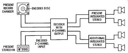
Fig. 8-12. Arrangement for reproduction from encoded discs, tape, or
fm broadcasts.
The separation between channels is about half of that generally obtained with the arrangement shown in Fig. 8-9, but with propitious allocation of separation to favor the front speakers ( where the effect to the listener is greatest) and to apply sufficient but reduced separation front to rear and rear left to rear right, this method provides an effect of concert-hall realism almost equal to that of the most expensive discrete four-channel system. Setup, connection, and operation of this system with the decoder shown in Fig. 5-62D connected as in Fig. 8-12 are as follows: Four separate power amplifiers ( two stereo amplifiers) and four speakers are required. A simple way to use the preamp and input selector sections of most stereo amplifiers and receivers to feed the decoder, while the power-amplifier sections of that amplifier or receiver are used to power the left front and right front speakers of the four-channel system, is to operate the tape-monitor ( also called tape-source) switch. This switch interrupts the normal signal path through the amplifier and introduces a new signal from outside the unit, independent of the input selector switch. The connections for this arrangement are shown in Fig. 8-13. If the unit has a separate control which permits selection of tape input without disturbing the normal input selector, you can easily connect the decoder.
The decoder can be inserted in the system anywhere ahead of the power amplifier. For example, the decoder can be inserted between separate preamp and power-amplifier components. How ever, some flexibility in system operation is lost with this method of connection, so the tape-monitor connection is recommended.
While the choice of equipment for a four-channel system is of concern to many, the criteria for good performance are less severe than for two-channel stereo. As is the case with two-channel stereo, good performance results when all four amplifier channels are the same and all four speakers are the same. However, the results are still totally satisfactory if the rear amplifier is of lower power and the rear speakers have narrower frequency range, because the rear ...
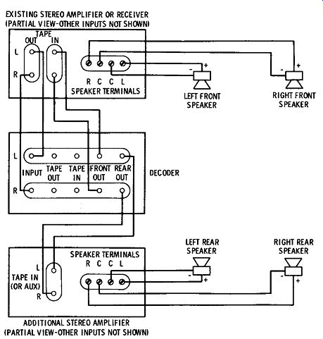
Fig. 8-13. Connection diagram for Stereo-4 decoder.
... channels are enhanced substantially by the front channels, especially at low frequencies, and vice versa. Program material which has ambient information (hall sound) in the rear requires less power and frequency response in the rear channels than does the type of pro gram material in which instruments are all around the listener. For best results, however, the two front speakers should be closely matched high-quality speakers.
With the decoder gain control set at maximum, the decoder output will be no higher than the input voltage from the tape jacks of the front amplifier. For this reason, the gain or input sensitivity of the rear amplifier must be high enough that the decoder output will drive it satisfactorily. If the sound level from the rear amplifier is sufficient when it is connected directly to the tape output jacks of the front amplifier, then the decoder will work with it as well.
Complete receivers ( amplifier with tuner), integrated amplifiers, preamps and power amplifiers, integrated compact systems, consoles, or combinations of these may be utilized for four-channel equipment. The electronic unit used to drive the front pair of speakers will be called the front amplifier, and the electronic unit used to drive the rear speakers will be called the rear amplifier.
The unit to which program sources ( phono, tuner, etc.) are connected should be considered the front amplifier. For this reason, a more complete unit ( stereo receiver versus stereo amplifier) should be considered for the front unit. If two similar units are to be used ( two amplifiers or two receivers), the better unit in terms of power output, distortion, etc., should be used as the front unit.
If the two pairs of speakers are not identical, the better pair should be used for the front speakers.
When the equipment has been selected, refer to Fig. 8-13 and proceed as follows:
1. Using shielded audio cables of convenient length, connect the front-amplifier tape-output jacks to the decoder input jacks.
2. Connect the decoder front-output jacks to the tape-input jacks on the front amplifier. At this point, you should have cables going to and from the front amplifier, connected to the decoder input and front-output jacks.
3. Connect the decoder rear-output jacks to the rear-amplifier input. If the rear amplifier has tape-input jacks, use them. If not, use the auxiliary or other high-level inputs.
4. Connect the four speakers to the appropriate amplifier output terminals. The speaker locations are named with the observer facing the "front" of the four-channel system. Thus, the left rear speaker is connected to the left speaker terminals of the rear amplifier. Be sure to connect all speakers in phase, as outlined in the speaker instructions and elsewhere in this Section.
5. If there is a tape recorder in the system, it may be connected to the tape-input and tape-output jacks on the rear of the decoder. These jacks duplicate the jacks previously used on the front amplifier, and, additionally, allow decoding of the output of the tape recorder into four channels.
6. Connect the ac line cord to a convenient outlet. If a switched ac outlet is available on one of the amplifiers, power will be applied when the amplifier is turned on, and the decoder master gain control can be left turned up all the time. In fact, if switched ac outlets are available on both the front and rear amplifiers, plugging the rear amplifier into the front amplifier and the decoder into the rear amplifier will permit the entire set of equipment to be turned on with the front-amplifier power switch.
7. Place the tape-monitor switches in the tape position to connect the output of the decoder into all four amplifier channels.
Start with the amplifier volume controls turned all the way down, the decoder master gain control turned all the way up, and the decoder function switches in the source decode position. Turning up the amplifier volume controls will provide the desired sound level in the room and also permit adjustment of front-to-back balance. If the volume controls are initially set for the loudest sound level you want in the room, with the front and rear sound levels about the same, then the master gain control on the decoder will reduce the sound from all four speakers equally as it is turned down.
After this initial adjustment, the rear-amplifier volume control can be used as the front-to-rear balance control. Adjust the rear sound level up and down slightly to move the balance point forward or backward in the room, and to adjust for best subjective effect. Enhancement of a two-channel classical work should provide a re-creation or simulation of the ambient sound as it originally existed in the hall where the recording was made. Normally this can be done by reducing the rear-amplifier volume somewhat, and perhaps turning down the rear treble control.
The left-right balance controls of both amplifiers work norm ally, although there will be less need to adjust the left-right balance in either front or rear.
8. To return to straight-through two-channel operation of the front speakers, (A) return the front-amplifier tape-monitor switch to the source position, and ( B) on the rear amplifier, either switch back to source, or switch out of auxiliary depending on the hookup; or simply turn down the volume control.
If a tape recorder is connected to the decoder as part of the system, it is possible to record conventional two-channel tapes, and play tapes through either the two-channel or four-channel system. The signals going to the tape recorder are identical to those coming from the tape-output jacks on the front receiver, where the recorder normally would be connected. If the de coder function switch is in the tape-monitor position, the out put of the tape recorder will play back through the front amplifier in normal two-channel fashion. If the function switch is in the tape-decode position, the output of the two-channel tape recorder will be decoded into four channels, just as a record or fm broadcast is decoded in the source-decode position.
Improved control may be had from the arrangement in Fig. 8-11 by using the decoder shown in Fig. 5-62G. The operation technique is similar to that just described, but this adapter has more features to provide overall balance of the channels to each other with ganged controls. It also provides for monitoring visually and aurally, and it can provide "synthesis" for program material that is or is not ...
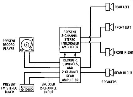
Fig. 8-14. Use of adapter-decoder-amplifier in 4-2-4 system.
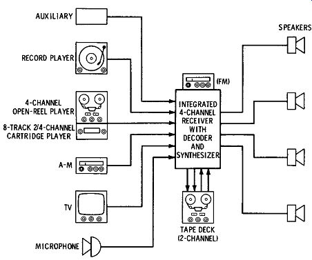
Fig. 8-15. System for two or four discrete channels or 4-2·4 encoded
operation.
... encoded to develop delayed or phased outputs to the rear channels for simulated effects of four discrete channels.
Fig. 8-14 shows a similar system using a combination adapter decoder-integrated-amplifier made especially to adapt two-channel systems to four channels with only one additional electronic unit and two additional speakers. Fig. 8-15 shows an integrated fm stereo receiver and four-channel amplifier with built-in decoder and the capability of operating in two-channel regular or four-channel de coded modes with auxiliary inputs and outputs for two- and four channel operation. This system will play four-discrete-channel out put from tape, both open-reel and cartridge, as well as process en coded 4-2-4 discs and fm broadcasts.
ELABORATE ARRANGEMENTS
A complete hi-fi system that does most everything one would ordinarily want with highest-quality reproduction could have many units. A fairly complete arrangement is shown in Fig. 8-16. It is expected that the speaker system, basic amplifier, control, and other units would be top quality, perhaps costing as follows:
(A) Main speaker system
( B) Auxiliary speaker system ( 2)
( C) Speaker switcher and controls
( D) Basic amplifiers
( E) Control center
( F) Record changer with reluctance cartridge and diamond stylus
( G) Am/ fm tuner
( H) Turntable with dynamic cartridge, diamond stylus, and hysteresis motor (I) Tape recorder ( J ) Television chassis ( K) Microphone
$250 to $700
$100 to $300
$20
$100 to $200
$100 to $150
$85
$100 to $150
$150 to $200
$200 to $400
$150
$50
One can spend several thousand dollars for top-quality components such as the preceding. In addition to these, there are such items available as: automatic time ( on and off) switching controls, disc-recording equipment, intercom, telephone pickups, and others.
SYSTEMS LAYOUT
There are aspects of high-fidelity systems design that may be related to all the members of a family. Sometimes it is better to sacrifice highest fidelity of sound reproduction to gain better family relationship. A compromise in placement of the units may bring better harmony everywhere, both in music and family relations. For instance, one never knows where a wall speaker will sound best until the unit is tried in the wall, but once the hole is made in the wall it is difficult to move.
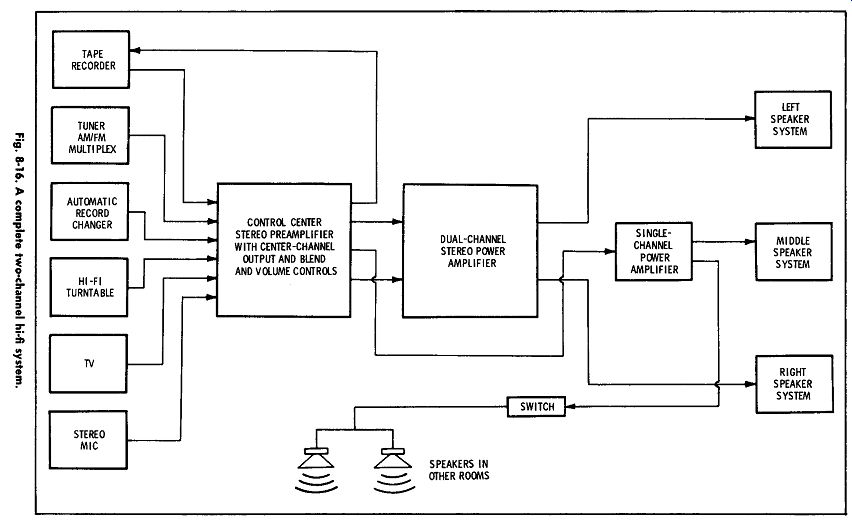
Fig. 8-16
Problems in physical layouts of hi-fi equipment break down into three groups:
1. Speaker placement
2. Operations and control position
3. Units that can be concealed The last is no problem anywhere. The first two problems may be solved in a combined manner or separately. The controlling factor is the room acoustics, and so we will begin with speaker placement.
Speaker Placement in Single-Channel Systems
The placement of the speakers is a very important problem, be cause proper speaker positioning is necessary in order to obtain adequate distribution of the highs and at the same time make adequate provision for bass reinforcement. If microphones are involved, improper speaker placement may cause feedback. Added to this is the problem of minimizing interference between speakers.
There are no rules which can be applied to all installations, but there are a number of points which should be observed when selecting speaker locations.

Fig. 8-17. Speaker placement in square and rectangular rooms.
(A) Speaker in corner of room. (B) Speaker in only one wall. (C) Placement of speaker for a rectangular room.
(A) Wrong way. (B) Right way.
Fig. 8-18. Speaker placement in L-shaped room.
Speakers should never be placed at two ends of a room. As a rule, they can be mounted on one wall or in one corner of a room. Most of the sound heard by a listener should come from one point or from speakers which are equidistant from the listener.
A number of typical examples will serve to point out the procedure used in locating speakers. Fig. 8-17 shows two methods of mounting a speaker in a square room. In Fig. 8-17A, the speaker is mounted in one comer of the room. This gives the best distribution of sound when a single speaker is used. The maximum high-frequency distribution can be expected only over 90 degrees; consequently, this is the only method of obtaining full coverage. In addition, when a comer folded horn is used, the walls act as a part of the system, and an additional advantage of the comer application is gained. To give the proper assist to the folded corner horn, there should be wall lengths of at least four feet beyond the enclosure. In Fig. 8-17B, the speaker is mounted on one wall ( or in it), giving less than full coverage of the highs. This same arrangement for rectangular rooms ( Fig. 8-17C) will give better distribution because of reduction of reflection.
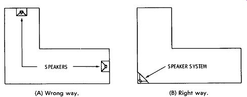
Fig. 8-18 shows the right and wrong ways to position speakers in an L-shaped room. Fig. 8-18A shows the wrong way, in which a speaker is mounted at the end of each leg of the L. In Fig. 8-18B, the correct position is shown. The speaker system is arranged at the junction of the legs of the L, bisecting the angle to obtain even distribution of sound.
Fig. 8-19 shows a two-room installation with adjoining rooms.
A single speaker is mounted in each room. With this arrangement, the speaker lines are kept quite short, and if a listener is able to hear lows originating from two speakers, the speakers will be almost equidistant from him. This condition will exist near the openings between rooms.
Using an inside wall as an infinite- baffle arrangement may turn out in some instances to be an excellent low-cost arrangement, but there are many factors involved that may reduce the effectiveness.
In an average home, a speaker may be mounted in a wall between...
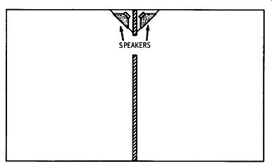
Fig. 8-19. Placement of speakers in adjoining rooms.
... two rooms or between a room and a large closet. In any case, the baffle room must be in proper acoustic relation to the speaker to act as a first-class baffle. Room resonances in either room can be reduced by drapes on opposite walls, but this may not suit the decor. Severe reflections and other interference from the baffling room back to the speaker will cause distortion. A baffling room or closet must be acoustically treated to be effective. Chances are great that the acoustic nature of the room is such that a location where the infinite-baffling technique can be used to best advantage is not the optimum location for the speaker, and as a result the distribution of the highs only covers half or less of the room. Experience has shown that cutting up a house to provide for infinite baffling is not advisable as a practical matter on either a short- or a long-term basis. However, excellent results can be obtained if you persist and have a little luck.
In almost all indoor installations, the speakers are mounted from a normal sitting ear level on up to near the ceiling. This allows a clear path for the sound to a listener in any part of the room. Floors and ceilings are not recommended for speaker mounting, because the effects seem unnatural.
In outdoor installations, the speakers should be mounted 10 feet or more above the ground. All speakers should be located at the same point. This point does not necessarily have to be at the point of direct pickup, since in many outdoor installations sound from the point of pickup is a negligible factor.
Speaker Placement in Stereo Systems
As in the case of monophonic reproduction, the most critical link in the stereo reproducing chain is the speaker system. The requirements for stereo are even more rigid because proper speaker placement and balance are important for production of the stereo effect.
The use of all of the principles discussed in Sections 6 and 7 for speakers and enclosures is more important in stereo systems than in mono systems. The reader is therefore referred to these Sections for fundamentals which concern the design of each individual speaker system. In stereo, we are primarily concerned with the use of at least two of these systems and how they are coordinated for best enjoyment of the stereo effect.
The exact requirements for placement, relative frequency response, and relative power-handling capabilities of the speaker systems to be used for stereo are matters on which even the most respected authorities differ. This is probably because the placement of the microphones at the source, the relative size of the source ( orchestra, chorus, etc.), and the nature of the sounds involved differ widely in the different programs to be reproduced. One set of conditions cannot be optimum for all of them. So it is not possible to give positive single answers to most of the questions which the reader will have about acoustic reproduction for stereo. We shall therefore concentrate on reviewing some of the different ideas that have been set forth on the subject, aware that the listener is best qualified to make the final choice for himself.
Matching Speaker Systems---It seems generally agreed that the ideal situation is two or four completely matched full-range reproducing systems. Some have suggested that "reasonably good" stereo reproduction can be had with one elaborate system of speakers ( for center, right, or left) and one or more cheaper systems which can have limited frequency response (high) and perhaps a small degree of distortion. However, this suggestion is usually made in connection with a transition from a monophonic system to a stereo system, and this arrangement is not considered a good substitute for two or four top-notch speaker systems.
In some compromises, cognizance is taken of the fact that the stereo effect is obtainable only with the higher-frequency signal components. Because of the large wavelengths of the lower frequencies when compared to the spacing between speakers and the distance to the listener, the low-frequency sounds seem to come from a wide area. ( For example, at 50 Hz, the wavelength is over 20 feet.) Also, differences in phase due to sound-source location differences are not noticeable at low frequencies, and the stereo effect is lost ( although presumably there is still an intensity difference ) . The fact that the stereo effect is not as prominent at low frequencies has led to the idea of concentrating the low-frequency components ( which contain the most power) in one high-power woofer located in the center. The left and right speakers then need only reproduce the relatively low-power higher-frequency components. The left and right speakers should be carefully matched, but lower-priced speakers than are usually employed in a full-range system can be used. The use of a middle speaker also minimizes the "hole-in-the-middle" effect.
The left and right speaker systems must also be balanced as to phase. If the connections to one of the voice coils are reversed, the sound from one speaker tends to cancel that from the other, leading to distortion and lowered output. Correct phasing can be recognized as that resulting from the connection that gives the greater output.
The polarity of each speaker is not important as long as both are phased the same way. Phase checking of speakers is discussed later in this Section.
Placement---The ideal speaker placement is the same as that of the microphones with which the sound is picked up. Unfortunately, this cannot usually be arranged, because microphone spacing differs for different source material, and moving speakers around to match the program is not practical. Also, the layout and decor of the room must be considered, because, of course, the average home cannot be "designed around" the high-fidelity systems ( although in isolated instances this has been done!). Probably the best general guide to placement is the triangle illustrated in Fig. 3-1. First determine approximately where the listeners will sit; then draw an angle of from 30 to 45 degrees between there and the wall where the speakers are to be located. The points where the two sides of the angle inter sect the wall are the two approximate locations for the speakers.
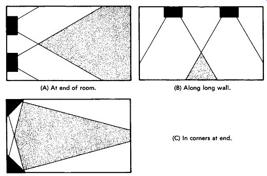
(A) At end of room. (B) Along long wall. (C) In corners at end.
Fig. 8-20. Three ways of placing stereo speakers.
As illustrated in Fig. 8-20, the speakers may be placed along the end wall, along the side wall, or in two comers ( for which special "comer speakers" are available). As indicated by the shaded areas, the stereo effect is obtained over a much greater area if the speakers are placed at the end of a room. Only those areas within the coverage of both speakers can provide stereo effect. Notice also that it is not good to plan on being too close to the speakers (between them) be cause then, too, you will be out of the coverage areas.
At the high frequencies, at which the stereo effect is the greatest, the radiation beam of the speakers is the narrowest. This is some thing to keep in mind especially when you are using single speakers at the left and right. Most tweeters in dual speakers are now de signed to spread the high-frequency energy over most of the beam width of the middle-frequency range.
Where space is limited, and the speakers cannot be spaced far enough apart, various methods are employed to orient the speakers so that they radiate as though they were farther apart. In one such arrangement, the speakers are mounted at the ends of a rectangular cabinet, and doors in the end are opened part way to deflect the sound outward to the listener.
The Middle Speaker---As has been mentioned, many audiophiles believe in the use of a "middle" speaker, that is, a speaker located between the left and right speakers and reproducing a subdued combination of the right and left signals. The idea of this arrangement is to overcome what is known as the hole-in-the-middle effect and provide a wide curtain of sound. The hole-in-the-middle effect arises when the stereo effect is so pronounced that the listener be gins to distinguish two separate sources. This can be partially over come by diluting the stereo effect with a blending control. However, a middle speaker is best for removing the hole-in-the-middle effect without loss of the stereo effect. Signals from both channels are coupled to the middle speaker, which is operated at a lower level than either the right or left speaker.
The optimum arrangement for providing center-speaker operation is by mixing (blending) the outputs of the preamplifier and feeding the combined signal to a third amplifier channel for the middle speaker, as shown in Figs. 8-8 and 8-16. The preamplifier outputs must be combined in such a way that they do not cross over and produce interaction in the left and right amplifiers. A separate blend volume control will provide optimum results.
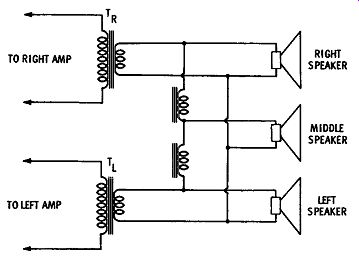
Fig. 8-21. Combining L and R outputs for a middle speaker.
A lower-cost way to provide a signal for the middle speaker by combining the signals at the amplifier outputs is given in Fig. 8-21.
The L and R signals are fed to the middle speaker through choke coil filters that are designed to pass low-frequency signal components and block the middle- and high-frequency components. However, the filter chokes are far from perfect filters, and interaction between the two signals is fed back through them.
A more efficient arrangement is given in Fig. 8-22. The middle speaker is of special design, having a dual voice coil; that is, a separate voice-coil winding is employed for each circuit. Although the filtering is similar to that in Fig. 8-21, the voice coils are so small that the coupling between them is negligible, and separation be tween the left and right circuits is good. Dual-voice-coil woofers, such as that shown in Fig. 6-35, are now made by nearly all speaker manufacturers.
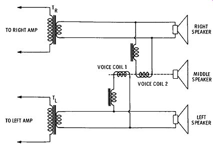
Fig. 8-22. Combining L and R outputs for a two-voice-coil middle speaker.
Four-Channel Speaker Placement
Placement of speakers in a four-channel system should follow all the principles already discussed, plus a few rules related only to the four-channel surround mode.
Many sounds from the sides and rear that were originally re corded on a two-channel stereo disc are masked by louder passages.
Since the human ear will "listen to" and discern only the louder sounds from a given direction, the human hearing system will then "mask" the weaker sounds from that direction even though they may be necessary to render the music properly. Therefore, it is desirable to separate these sounds and deliver them from their original bearing points (directions) from the average listener position at the original performance. When these weaker sounds are coming from a different direction, they are more apparent to the ear.
Four-channel stereo systems deliver separated sounds in a mode similar to that in which they were recorded and distributed to the four channels. The speakers in turn should be arranged in the room to deliver the reproduced sounds from directions that simulate the spatial distribution of the original sounds.
For convenience, the speakers are usually placed in the four comers of a room, but a better arrangement is to place the front speakers in the comers and the rear speakers nearer to the listener, somewhat forward of the rear wall and to the side, as shown in Fig. 8-23A. The volume from the rear speakers should be subdued compared with the volume from the front speakers. The left and right speakers should be balanced in volume level.
A method of speaker placement for derived-sound ( 2-2-4) program reproduction in the absence of a separate specific back signal even with the rear-level control at maximum is shown in Fig. 8-10.
This method assures that in the usual listening environment, where the listener sits nearer to the back speaker, proper placement and emphasis of instruments or voices will be retained on the sound stage in front of him ( front dominance). Since the back speakers are usually closer, and form a wider listening angle, the fact that the back speakers reproduce some of the front left- or right-channel information, in addition to the reflected sounds from the sides and rear, provides more sharply defined differences in intensity which preserve the maximum effect of directionality. In effect, the ear often senses or perceives greater effective aural separation than the electrical signals actually provide ( psychoacoustic response) . Four-directional effects are achieved because the information in the front and rear speakers is different-not because there is some front information appearing with reduced level or different phasing in the rear. As explained previously, the added rear speakers make it possible for the ear to perceive separated signal information from different bearings, which contributes to realism but which has previously been masked when combined with the output from the front.
The derived four-channel sound output to the rear speaker includes a simple method for extracting rear information from two channel material, and in turn reduces the front information when it is reproduced through the rear speakers. This diversion of front information to the rear enhances the proportion of rear sound to add front and back directionality to the conventional left and right orientation, as shown in Fig. 8-10. Derived four-channel output can also have speaker placements as shown in Fig. 8-23.
Figs. 8-23A through 8-23D show recommended four- and six speaker placement arrangements. It is suggested that the best arrangement will be found by trial and error, since the shape of the room and furniture placement in the room have a considerable effect on proper speaker placement.
------
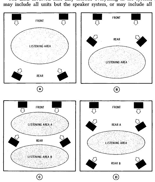
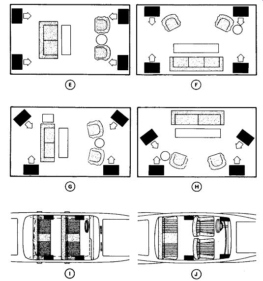
Fig. 8-23. Speaker arrangements for four-channel systems.
Experiments have shown that it may be desirable to raise the level of the rear speakers above the level of the front speakers to improve the spatial effects, with each rear speaker at a different height.
Figs. 8-23E through 8-23H show suggested arrangements in a rectangular room with furniture layouts taken into consideration.
Figs. 8-23-I and 8-23-J show recommended four-channel arrangements for use in automobiles.
Location of Program Sources, Amplifier, and Control Equipment
The units involved here may include everything in the system, may include all units but the speaker system, or may include all units but the speaker system and the basic amplifier. A basic amplifier completely controlled from a preamplifier could be kept any where in the building as long as it has sufficient ventilation.
Wall Cabinets--Sectionalized wall cabinets of all types are available. These cabinets are usually of modem design with spaces to fit any conceivable arrangement, including television and speaker with a full-sized bass-reflex enclosure. One such arrangement is shown in Fig. 8-24. Many others are available. Provision can also be made for extras such as books and ornamentation if desired.
Record player, tuner, controls, and amplifier are all located near each other, and the point of operation is at the nearest point to the listener that it can be without remote control. Speaker systems should be mounted at ear level or above and slightly off center of the room. The best position for such a system mounting is on the narrow wall nearer one comer. Make all connections short, shock mount the pickup units and preamplifier, and ground everything metallic.
The same ideas can be used in novel home-modified break fronts and other odd furniture pieces for matching period decorated or early American homes. Usually, the speaker is best mounted separately to gain the advantage of a properly designed enclosure.
Packaged units are commercially available at prices from $160 to $1800. The advantage of these is that one gets a complete set of matched components with no further engineering or construction required-just plug it in. The limitation is that one has no choice in variations of arrangement to suit his individual taste.
Units in Separate Furniture Pieces--Several pieces of furniture may be separately set up to house the various components that must be operated. Table equipment and consoles are available for individually holding record players, tuners, and amplifiers. It is often convenient to have the operating position of the player, tuner, and controls located at an accessible spot convenient to the listening area, ...
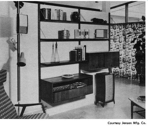
Fig. 8-24. A typical home stereo layout.
...to save steps. Here again, custom installation in separate furniture pieces to match the decor can be beautiful and practical.
Wall Units---If mounting the pieces in furniture is not desired, it is modern to mount operation control units in the wall. Several units are made to suit this application with modern and antique panels.
The type of unit most suitable for this kind of installation is a tuner with all controls built-in to provide a control center-otherwise several holes in the wall may be necessary. This may make a very convenient and space-saving operation, but it has disadvantages.
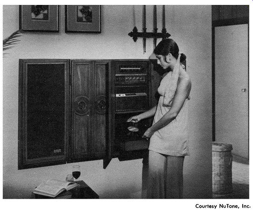
Courtesy NuTone, Inc.
Fig. 8-25. Example of wall-mounted stereo components.
The equipment requires a good-sized aperture in the wall, possibly with equipment protruding through the other side and internal wiring. The equipment is generally required to be within 4 feet of the phono pickup. These problems may be easily worked out when constructing new houses, but in old houses they may present many difficulties.
A variety of equipment for wall mounting is available. One example is shown in Fig. 8-25. The advantage is that valuable room space is conserved because a substantial portion of the equipment is located in the wall. The record-player unit swings outward during use and remains closed into the wall like a door when not in use.
Stereo speakers are mounted on another wall.
The equipment may in time become obsolete, and if it is removed, the new equipment may not fit in the same place. Holes in the wall are inconvenient to patch, and new plaster causes decorating problems. With these cautions in mind, it is suggested that one get the best equipment available and be sure the installation is the one that will be desired permanently before proceeding.
Closet Arrangements---Only shelves and enough room to move around in are required in a closet. If an available closet is located conveniently near the principal listening area, one may save considerable money in furnishing and matching, and the equipment will be protected from mechanical disturbance, prying fingers, and other problems. Certain types of home-built equipment or less ex pensive kits that "don't go" in the living area may be kept out of sight here. The wiring will be short and convenient, and all units will be located in one spot for convenience of operation and control. While speakers may be mounted on the same closet doors, this partly defeats the purpose of unit isolation, and the speaker system thus located does not compete with a good folded comer horn arrangement.
Combinations of all of the foregoing are permissible for any arrangement desired, except that one should keep in mind that the phono lead to the preamplifier should not be over 4 feet long.
SYSTEMS INSTALLATION
After the components of a sound system have been selected, and the positions of all the components and speakers have been deter mined, the actual job of making the installation begins. The work of installation consists mainly of mounting the equipment, connecting the control center, the amplifier, and the record player to the source of power, and connecting the speakers and program-source equipment to the amplifying equipment through suitable lines and cables. There are a few problems peculiar to each hi-fi installation which must be solved individually at the time the installation is being made.
Installing Program-Source Equipment
When leads from record players, tuners, tape equipment, and microphones are installed, care must be taken to avoid hum pickup, cross talk, and losses in frequency response and level.
High-impedance circuits are very susceptible to hum pickup.
Correct grounding of the turntable and pickup arm is exceedingly important in preventing pickup of hum. Connections carelessly made can negate all other precautions in design of equipment. The turntable frame and pickup should be connected by a flexible wire from the turntable frame to the pickup-arm base to the shield of the lead to the preamplifier. Be careful to avoid ground loops between all equipment. Inter-unit cables provide a complete ground system.
Alternate ground wires create ground loops which will usually in crease the hum level.
Keep the magnetic phono pickup or microphones more than 2 feet away from power lines and transformers to prevent induction of hum.
When long lines are used with high-impedance sources, with the exception of the crystal type, loss of high frequencies results.
When low-impedance microphone circuits are used, there is very little frequency discrimination or loss of level in cabling. These facts should be kept in mind when one is designing any system in which the input circuits must be run a considerable distance.
The cables used with high-impedance equipment usually consist of a single conductor with an overall shield and rubber covering.
The shield acts as one of the conductors in the microphone circuit.
The shield is grounded and is connected to the microphone case and microphone stand.
Either two- or three-wire shielded cable is often used. When two wire shielded cable is used, the shield is connected to ground at the amplifier, and to the chassis of the program-source equipment at its other end. The shield does not act as one of the microphone circuit conductors, and the likelihood of hum pickup with two-wire cable is less than with single-wire shielded cable.
Where microphone or other low-level circuits are carried for long distances in flexible cables, three-wire shielded cable is most effective. Two of the wires serve in the input cable circuit; the third is used as a ground lead. The shield is connected to ground at the amplifier end of the cable only. The source-equipment case is grounded through the third conductor.
When microphone or other input cables are installed permanently in floors or walls, lead-covered twisted or parallel pair may be used.
The capacitance of lead-covered cable is quite high; therefore, it can only be installed in short lengths when high-impedance pickups are used. The recommended overall cable length for low-level phono pickups is 4 feet or less. The capacitance of the long cable also impairs the high-frequency transmission. Since crystal pickups are not affected by capacitance, longer lengths of lead-covered cable may be used with them.
Permanently installed input cables can be plug-in connected to the control center and switched so that only those cables in use at any time are fed to the amplifier.
Control-Center and Amplifier Installation
When installing the controls and amplifier, be sure that they will receive proper ventilation; otherwise, components may be damaged by excessive heat.
When an amplifier must be located where vibration from a speaker or other source may cause microphonic noises, it should be mounted on shock-absorbing mountings or rubber pads. Such mountings are available in various sizes and thicknesses, based on the number of pounds the mounting will support while operating normally. To determine the size of the mountings required for an amplifier, the corners of the amplifier should be weighted separately. This is necessary because many of the heavy components are usually located near one end of the amplifier chassis with the result that the weights at the different comers are not the same. When the approximate weights have been determined, mountings of the proper sizes can be chosen. When the amplifier is mounted in this fashion, it should be grounded through a length of heavy braid.
The amplifier should be suitably fused. If the amplifier is not equipped with fuses, a fused power receptacle should be provided.
To protect the amplifier components, a 500-mA fuse can be connected between the center tap of the high-voltage winding of the power transformer and ground, as shown in Fig. 8-26. The entire hi-fi equipment is best powered from a single line from the electric power distribution board, with a 5-ampere fuse in the circuit.

Fig. 8-26. Method of fusing a power amplifier.
Speaker Installation
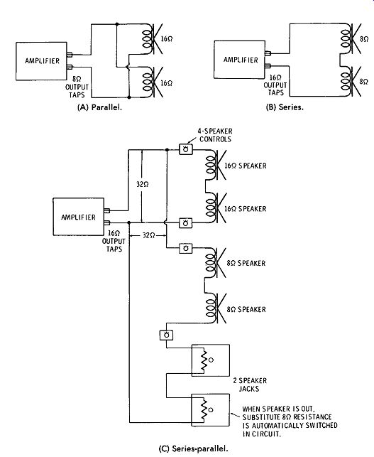
(A) Parallel. (B) Series. (C) Series-parallel.
Fig. 8-27. Typical multiple-speaker connection circuits.
When the speakers for a system are installed, the problems of impedance matching and power distribution must be solved. If the speakers are not properly matched, considerable loss in output will result. When a system uses more than one speaker, it is often necessary to have each speaker in the system radiate a different amount of power. Output impedances are usually 4, 8, 16, and 32 ohms to match directly a speaker or combination of speakers. Sometimes 500- or 600-ohm outputs are provided to match long lines to speakers at distances of several hundred feet or more.
Generally, hi-fi speakers are rated at 8 or 16 ohms. Speaker-matching networks and crossovers are generally rated at 16 to 32 ohms.
It is important to determine the specified impedance of the speaker or speaker system ( usually marked on the speaker, the speaker box, or the speaker literature) and to connect the terminals of the speaker or system to the matching terminals on the output of the amplifier.
Two 8-ohm speakers may be connected in series to match a 16-ohm output. Two 16-ohm speakers may be connected in parallel to match an 8-ohm output. Any combination of arrangements of this nature may be used. When connecting two or more speakers, check speaker phasing as described in following paragraphs. Typical multiple speaker connections are shown in Fig. 8-27.
In stereo systems, the amplifiers usually come with speaker connections clearly indicated. However, sometimes connections for combining the two channels into one for monophonic performance must be made by the owner. Fig. 8-28 gives both the parallel and series methods of connecting the two channels. The impedances must be matched by following the basic rules of series and parallel circuits.
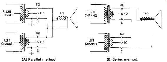
(A) Parallel method. (B) Series method.
Fig. 8-28. Connection of stereo outputs for single-speaker monophonic operation.
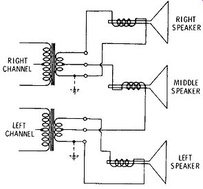
Fig. 8-29. One method of connecting a middle speaker in a stereo system.
Another situation in which the connections of speaker leads are involved is the addition of a third, or "middle," speaker to a two channel stereo system. One simple way to do this is by connecting the middle speaker to taps on the two transformers, as indicated in Fig. 8-29. This method is not ideal, however, since there is likely to be considerable interaction between the left and right channels, thereby diluting the stereo effect. Other, more efficient, methods were discussed earlier in this Section.
Speaker Lines--The wire used in speaker lines must be of sufficient size according to the impedance and power to keep the line losses within tolerable limits.
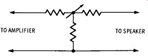
Fig. 8-31. A variable T-pad speaker control.
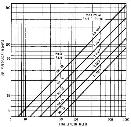
Fig. 8-30. Wire sizes for speaker lines.
When the speaker-line impedance is under 60 ohms, only short lines, not to exceed 100 feet, should be used. When a line impedance of 60 ohms or more is used, lines may be run for a considerable distance, providing wire of sufficient size is used. The curves of Fig. 8-30 give recommended wire sizes for lines of various impedances and lengths.
Speaker Switching---In many installations, it is necessary to have facilities for controlling the volume of auxiliary speakers and for switching speakers in and out of the system. When more than one speaker is used and one or more speakers must be separately con trolled, a variable T-pad may be placed in the circuit to control the speaker volume and to provide a substitute resistance in order to maintain constant load impedance to the system when the speaker is partially or completely turned off. Fig. 8-31 shows a circuit of an available unit which can be used to accomplish this. The substitute resistor should have a resistance equal to the impedance of the speaker or group of speakers being disconnected from the circuit.
To cut out or in speakers in various rooms, speaker switches able to carry up to 10 watts are available. These provide for up to three speakers and switch on any one or any combination of them.
Speaker Phasing--When a group of speakers are mounted at one point or close together so that they cover the same area, it is necessary that they be correctly phased. If the speakers are not phased properly, the sound waves from the improperly phased speakers will tend to cancel out, reducing the effective output of the system.
There are a number of ways to check the phasing of speakers.
Two speakers may be connected to an amplifier in the same manner they will be connected when installed, and placed close together, facing each other. A low-frequency signal from an audio generator or a record should be fed through the amplifier. By listening to the speakers, it is possible to determine whether or not the low frequencies are being cancelled. If the low frequencies are absent when the speakers are facing each other, then the phasing is correct if the speakers are to be mounted so that they face in the same direction. If the low frequencies can be heard when the test is made, then the low frequencies are not being cancelled, and the phasing is correct if the speakers are to be mounted facing away from each other. If the phasing is incorrect in either of the two cases just described, all that is necessary is that the connections to one of the voice coils be reversed.
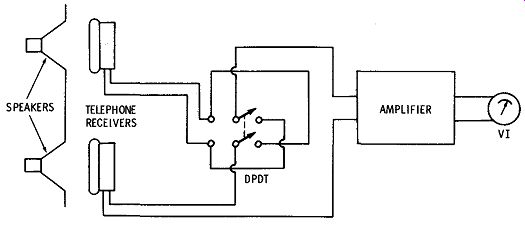
Fig. 8-32. Setup for determining speaker phasing.
The phasing of speakers may also be checked by using the circuit shown in Fig. 8-32. The apparatus consists of a pair of headphones connected to the input of an amplifier through two long cords and a double-pole, double-throw switch. The amplifier is equipped with an output indicator. The sound system whose speakers are to be checked for correct phasing should be turned on and a constant tone fed into its input. The double-pole, double-throw switch should be marked to show "in phase" and "out of phase." This may be done by holding both phones in front of one speaker and noting the position of the switch which gives the greatest indication on the output meter. This position should be marked "in phase," and the other position should be marked "out of phase." The equipment may now be used to check the phasing of two speakers. One phone is held in front of each speaker. If the greatest output is indicated when the switch is in the "in phase" position, then the speakers are phased properly.
In stereo systems, phase checking and correcting are made relatively simple. In most stereo systems, a phase-reversing control is included, connected either in the speaker output circuits or earlier in the amplifier chain. However, this control does not provide for phasing of the center speaker. If a single tone or other signal is applied to the inputs of both channels at the same time, the relative outputs from the right and left speakers will indicate the phasing.
If the phasing is wrong, the two signals will differ by 180 degrees and tend to cancel each other. If the phases are correct, the signals reinforce each other. Thus, the correct phasing should produce much greater volume.
It should be remembered that there is a difference between speaker phasing and system phasing. The final output phase depends on the windings of the output transformers, connections between preamplifiers and amplifiers, connections of cartridges and input devices, and other things besides speaker connections. Therefore, checking the relative phasing of the speakers themselves is not al ways enough.
FEEDBACK
Careful attention must be given to the factors which create feed back; otherwise, considerable trouble will be experienced. There are two forms of feedback. They are acoustic feedback, which is caused by coupling between the speakers and the program-source units, and electrical feedback, due to capacitive coupling between the output circuits and the input circuits.
Electrical feedback can be avoided by keeping the input and out put wiring and components well separated and shielded.
Mechanical or acoustic feedback is often difficult to eliminate and, in severe cases, may limit the usable output of a system. Mechanical feedback effects and microphonics may be caused by direct or resonant coupling between the speaker system and the program source equipment, or through mechanical pickup in the first-stage elements of the preamplifier or the mechanical elements of phono and microphone pickups. This may be corrected by mounting the units concerned on rubber, as has been described, or by moving the units concerned out of the mechanical-contact area or resonant condition area. Moving the speaker should have the same effect.
Feedback manifests itself as a continuous tone or tones and spurious noises radiated by the speakers of a sound system. Feedback can be avoided by careful attention to the location of speakers and microphonic elements of the system.
There are a few general principles of microphonics and speaker location which, if followed, give reasonable assurance that little or no trouble will be experienced with feedback other than feedback due to direct microphone pickup.
A microphonic element may be described as any element located in the hot circuits of the front end of the system. The most typical examples are tubes which are highly sensitive to any vibrations of their elements. A vibrating element in a tube in the input stage may induce the same effect as a microphone in the circuit by variation of plate-to-cathode resistance, thereby introducing undesirable interference.
A microphonic element should never be located in front of a speaker. If the speaker or speakers used in a system are located in front of the microphonic elements, the possibilities of feedback will be greatly reduced.
Speakers should not be mounted close to reflecting surfaces. When there is a flat surface close to and in front of the speakers, sound will usually be reflected by the surface.
If the system is installed in a location and is intended for use in a room filled with people, feedback may occur when the room is empty, but may not occur when the room is full of people.
Cardioid and other directional microphones are often very effective in eliminating feedback. The side of the microphone which is not sensitive to sound should be pointed in the direction from which the reflected sound is coming.
Attenuation of high-frequency response when equipment is used in a room with hard walls is desirable. Under these conditions, feed back usually occurs due to reflected sound, and, since the high frequencies reflect more efficiently than do the low frequencies, attenuation of the high frequencies usually reduces feedback effects. The high-frequency tone control is usually useful when background music is being reproduced as at dinner, etc. Under these conditions, the high frequencies should be attenuated, since they tend to make conversation difficult.
Control of low-frequency response when speech is being reproduced is desirable. Under these conditions, attenuation of the lower frequencies helps remove the "tubbiness" which occurs at times in certain types of installations.
==============