All servicing with the oscilloscope is based on waveform analysis and interpretation. Therefore, an introductory explanation of waveforms is required. The most basic waveform is the sine wave, illustrated in Fig. 1-1A. We describe a sine wave in terms of degrees and volts.
Its peak voltage is measured from the reference (zero) line to the 90 degpoint on either the positive or the negative half-cycle. Peak-to-peak voltage is measured from the 90 deglimit to the 270 deg limit. Its rms voltage is 0.707 of peak voltage. We also describe a sine wave in terms of time.
Thus, if 360 deg are completed in one microsecond, the wave is said to have a frequency of one million hertz, * or one megahertz (1 MHz). The basic distinction between amplitude and frequency is shown in Fig. 1-1B.
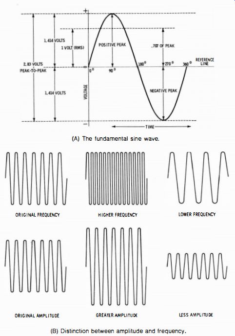
Fig. 1-1. Basic waveforms. (A) The fundamental sine wave. (B) Distinction
between amplitude and frequency.

Fig. 1-2. Typical pulse and sawtooth waveforms.
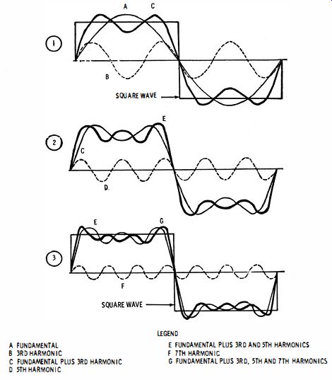
Fig. 1-3. Build-up of a square wave from sine waves.
However, sine waves as such are in the minority in the vast array of waveforms encountered at the service bench. For example, we will observe pulse and sawtooth waveforms frequently, as illustrated in Fig. 1-2. Horizontal sync pulses and sweep-deflection waveforms are prime examples. Nevertheless, the sine wave remains the basic element in a complex waveform. For many practical situations, we regard a square wave as being built up from sine waves, as illustrated in Fig. 1-3. Similarly, we may consider that a sawtooth wave is built up from sine waves, as shown in Fig. 1-4. A positive pulse followed by a negative pulse is built up as seen in Fig. 1-5.
More sophisticated analyses of square waves and pulses require the measurement of rise time. This measurement is made with a triggered- sweep scope that has a calibrated time base. Fig. 1-6 illustrates how a pulse is expanded by speeding up the sweep until the rise time of the waveform is easily measurable on the scope screen. When we state that we are observing a 20-microsecond pulse, we refer to the pulse width. In other words, the pulse has a duration of 20 microseconds.
This is evident from the first photo in Fig. 1-6; the sweep speed is 0.02 milliseconds (20 microseconds) per centimeter, and the pulse duration extends over one centimeter, or one major division on the scope screen.
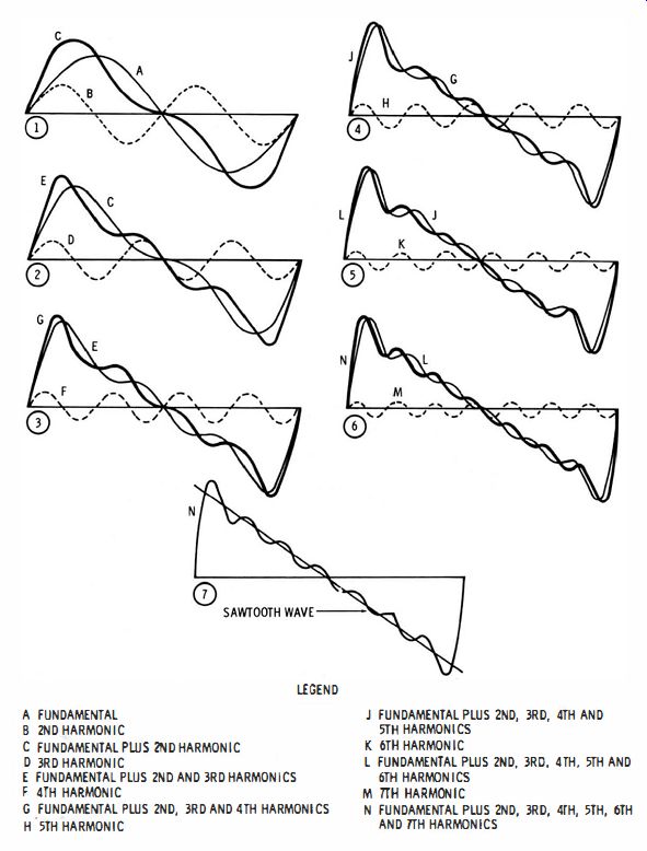
Fig. 1-4. Build-up of a sawtooth wave from sine waves.
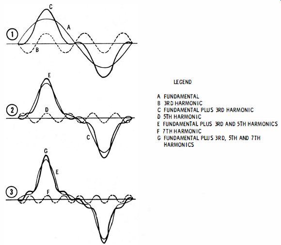
Fig. 1-5. Build-up of a positive pulse followed by a negative pulse.
Apprentice technicians are sometimes puzzled by the fact that the leading edge of a square wave may be invisible if the rise time is comparatively fast. This is a result of the swift travel of the electron beam during the rise interval. Next, if the sweep speed is increased, the leading edge becomes more clearly visible because the intensity control can then be advanced considerably without burning the screen. For example, observe the difference in leading-edge displays in Fig. 1-6, from sweep speeds of 0.02 ms/cm to 0.04 !-,-s/cm.
Rise time is defined as the elapsed time from the 10-percent to the 90-percent amplitude points on the leading edge of the pulse, as shown in Fig. 1-7. This measurement is also made on waveforms other than square waves and pulses. When a square wave is passed through an RC differentiating circuit, it is changed into positive and negative exponential pulses. Fig. 1-8 shows a universal RC time-constant chart that details the output waveforms for both differentiating and integrating circuits. The RC time constant is equal to ohms multiplied by farads, and the product is in seconds. Note in Fig. 1-8 that the output from an integrating circuit rises from 10 percent to 90 percent of maximum amplitude in approximately two time constants. Similarly, the output from a differentiating circuit falls from 90 percent to 10 percent of maximum amplitude in approximately two time constants. Both waveforms pass through their 50 percent of maximum amplitude points at the end of 0.707 time constant. At the end of five time constants, both waveforms have attained practically their steady-state, or resting, values.
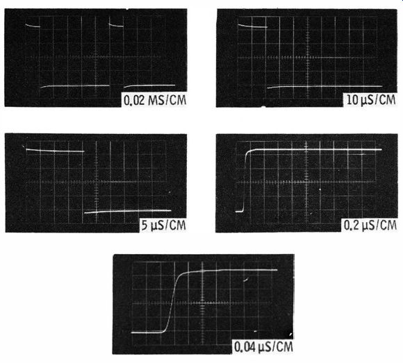
Fig. 1-6. Expansion of a 20-microsecond pulse as the sweep speed is progressively
increased.
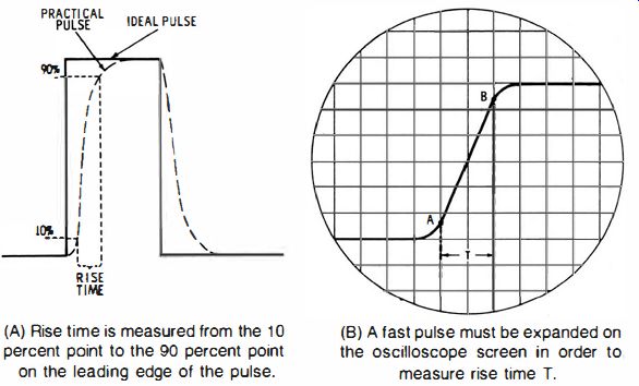
Fig. 1-7. Graphical definition of the rise time of a pulse. (A) Rise time
is measured from the 10 percent paint to the 90 percent point on the leading
edge of the pulse. (B) A fast pulse must be expanded on the oscilloscope screen
in order to measure rise time T.
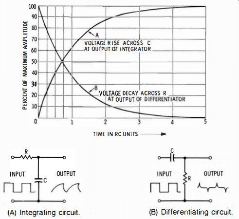
Fig. 1-8. Universal RC time-constant chart showing the effects of integrating
and differentiating circuits on a square-wave input.
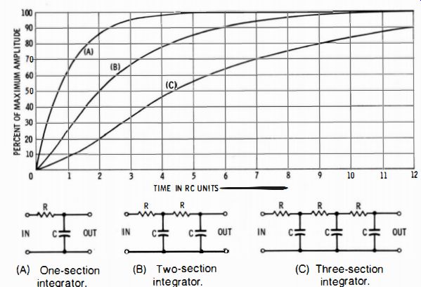
Fig. 1-9. Universal time-constant chart for one-section, two-section, and
three-section integrator circuits. (A) One-section (B) Two-section (C) Three-section
integrator. integrator. integrator.
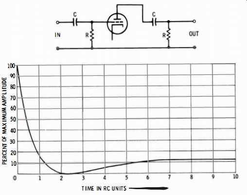
Fig. 1-10. Universal time constant chart for Re-coupled amplifier with two
RC sections.
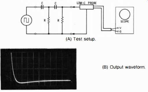
Fig. 1-11. Square wave response of a two-section symmetrical differentiating
circuit. (A) Test setup. (B) Output waveform.
Of course, electronic circuitry generally employs more complex circuits than simple RC differentiators and integrators. For example, a two-section or three-section integrator might be "packaged" in an encapsulated unit. Fig. 1-9 shows a universal time-constant chart for such integrators. Observe that the rise time increases progressively as more RC sections are connected in cascade. Furthermore, the waveform changes shape; the output waveform from two-section and three-section integrators is not a simple, but a complex, exponential waveform.
Another very practical example of RC sections in cascade is provided by an ordinary RC-coupled amplifier, as shown in Fig. 1- 10.
This is a universal RC time-constant chart for the low-frequency square-wave response of the illustrated circuit. Note that the tube provides isolation between the two RC sections; therefore, the second section does not load the first section. In turn, the output waveform is somewhat different from a situation in which the tube is not present.
This fact is evident in Fig. 1- 11. The great utility of universal RC time-constant charts is that they show the normal shape of the waveform and its development in time, regardless of the time constant itself. In other words, the progressive amplitudes of the waveforms are related to time in RC units. However, there is a limitation in the Fig. 1-10 chart, and in the B and C waveforms shown in the Fig. 1-9 chart; in either case, the Rand C values in the second section (or in the third section) are the same as in the first section. In other words, these are normal waveforms for symmetrical RC networks.

Fig. 1-12. Square-wave response of a 1-2 unsymmetrical two-section integrator.
(A) Test setup. (B) Output waveform. (C) Output waveform; sweep speed reduced
one-half.
Suppose that a two-section RC integrator is unsymmetrical, as shown in Fig. 1-12. The RC values in the second section are doubled.
Now, the output waveform rises more slowly than for a symmetrical network. In the first photo of Fig. 1-12, the sweep speed is one centimeter per RC unit; in the second photo, the sweep speed is one-half centimeter per RC unit. Note that the waveform in Fig. 1-12 rises to 50 percent of maximum amplitude in approximately five time constants. On the other hand, curve B in Fig. 1-9 rises to 50 percent of maximum amplitude in two time constants.
The network in Fig. 1-12 is called a 1-2 configuration because the RC values in the second section are twice as great as in the first section. Now, suppose we reverse the input and output terminals of the network; then we have the 2- 1 configuration shown in Fig. 1- 13.
Note that reversal of this network does not change its square-wave response-the output waveform is the same in both Figs. 1-12 and 1-13. It must not be supposed, however, that this fact is true of all RC networks-in general, the output waveform will be changed by reversing the input and output terminals.
Observe the network shown in Fig. 1-14; it may be called a 1-2/2-1 integrator. If its input and output terminals are reversed, we obtain the 2-1/1-2 integrator shown in Fig. 1-15. The output waveform for the reversed network is quite different. Therefore, it cannot be generally assumed that a reversed RC network will develop the same output waveform.
To return briefly to the topic of waveform voltages, we must realize that the positive peak voltage of a complex waveform is usually different from its negative peak voltage. For example, Fig 1-16 shows the peak voltages for a pulse waveform. Although they are widely different, their sum is nevertheless equal to the peak-to-peak voltage of the pulse waveform.
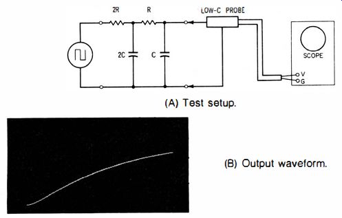
Fig. 1-13. Square wave response of a 2-1 unsymmetrical two-section integrator.
(A) Test setup. (B) Output waveform.

Fig. 1-14. Square wave response of a 1-2/2-1 unsymmetrical two-section integrator.
(A) Test setup. (B) Output waveform.
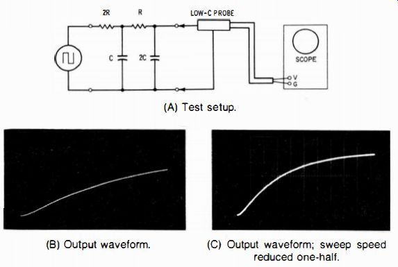
Fig. 1-15. Square wave response of a 2-1/1-2 unsymmetrical two-section integrator.
(A) Test setup. (B) Output waveform. (C) Output waveform; sweep speed reduced
one-half.

Fig. 1-16. Voltage components of a pulse waveform.
All troubleshooting with the oscilloscope can be classified under one or more of the following basic tests:
1. Signal Tracing. This test consists of checking for the presence or absence of a signal voltage at successive points through a signal channel. An audio-frequency, radio-frequency, intermediate-frequency, or video-frequency signal may be involved.
2. Waveform Checks. This test comprises amplitude (peak-to-peak voltage) measurement and waveshape observation. These waveform characteristics, in turn, are compared with those specified in the receiver service data.
3. Frequency Response. A frequency-response test displays a curve or pattern on the oscilloscope screen which shows the relative output voltages at all frequencies within the passband of an rf i-f, or vf amplifier. This response curve, in turn, is compared with the curve specified in the receiver service data.
4. Phase Checks. A phase test displays a pattern on the scope screen which shows the phase difference between a given signal and a reference signal. Specialized test signals may be employed, particularly in color-tv test procedures, as specified in the receiver service data.
5. Frequency Measurement. Frequency tests are made to best advantage with a triggered-sweep scope that has a calibrated time base. For example, the accuracy of a square-wave generator or an audio oscillator can be easily checked in this manner.
6. Time Measurement. Time measurement must be made with a triggered-sweep scope that has a calibrated time base. For example, the width of pulses in solid-state horizontal-sweep circuits, or the periods of pulses in tv digital circuitry can be easily checked in this manner.
With this brief introduction to the subject of waveform analysis, we turn to the scope itself and consider the operation of controls in free-running and triggered-sweep scopes. Certain additional considerations of waveform principles will be noted incidentally in our discussion of troubleshooting techniques. If it is inconvenient for you to make frequent reference to charts and other basic data in this guide, it may be advisable to have photo-static enlargements made that can be tacked on the wall over your service bench. This procedure can minimize the time required to analyze a basic waveform. Non-basic waveforms must be checked by consulting the service data for the receiver under test.