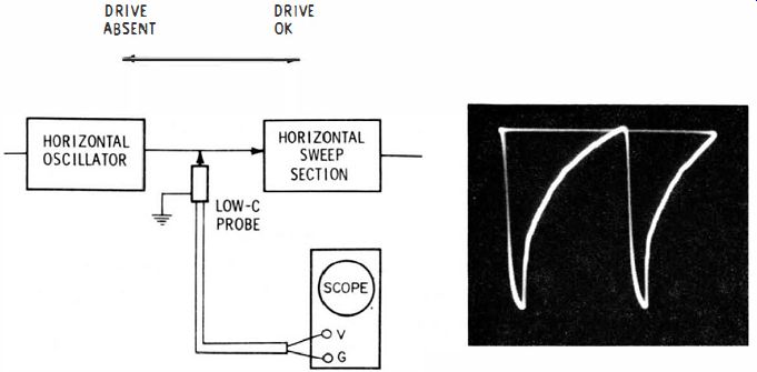
Fig. 7-1. Check drive first.
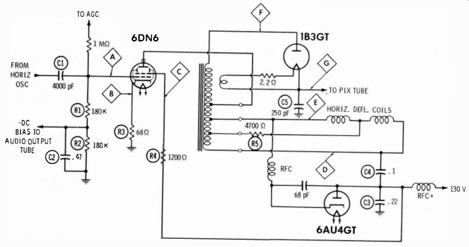
Fig. 7-2
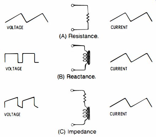
Fig. 7-3. Voltage waveforms needed for a sawtooth current.
The horizontal-sweep section has a reputation of being the "toughest" section in a tv receiver. While it is somewhat more complex than some of the other sections, logical waveform checks greatly simplify what can be a time-wasting trial-and-error procedure. Always check the drive waveform first, as shown in Fig. 7-1. This immediately sectionalizes a horizontal-sweep symptom. If the drive is absent or weak, the trouble is in the horizontal oscillator. Normal drive, however, indicates trouble in the sweep section.
There is one exception to this general rule: if the horizontal oscillator should obtain plate-supply voltage from the B+ boost circuit, weak drive can result from sweep circuit defects which reduce the boost voltage. In that case, confirm the possibility by measuring the boost voltage. If the boost voltage is low, you can connect a bench power supply to the oscillator B+ line to restore normal drive.
SWEEP-CIRCUIT TROUBLESHOOTING
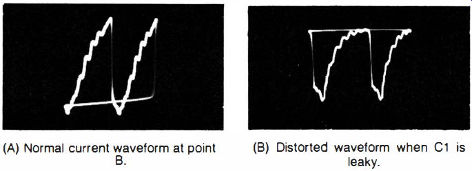
Fig. 7-4. Normal and abnormal waveforms at point 8 of Fig. 7-2. (A) Normal
current waveform at point (B) Distorted waveform when C1 is leaky.
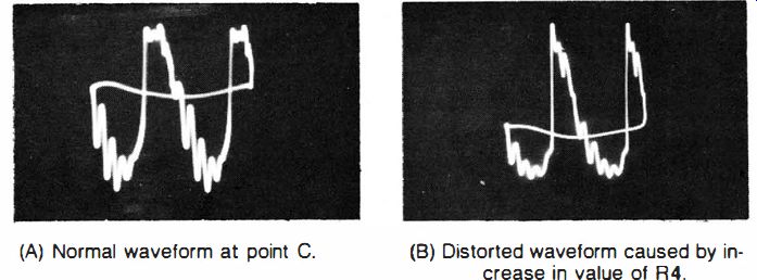
Fig. 7-5. Normal and abnormal waveforms at point C of Fig. 7-2. (A) Normal waveform
at point C. (B) Distorted waveform caused by increase in value of R4.
The illustrated arrangement in Fig. 7-2 uses the popular autotransformer circuit. This is the flyback transformer which matches the plate resistance of the 6DN6 output tube to the deflection-coil impedance for maximum power transfer. It also steps up the flyback pulse voltage for the high-voltage power supply.
The center-tapped yoke has a 4700-ohm damping resistor to minimize ringing. Voltage and current waveforms in the deflection circuit have different shapes, because the circuit is reactive (inductive). A complex voltage drives the same current waveform through a resistive circuit. But this complex voltage drives a different current waveshape through a reactance or impedance, as depicted in Fig. 7-3. Both voltage and current waveforms are used in signal-tracing horizontal sweep circuits.
The drive waveform to the grid of the horizontal-output tube is a voltage waveform. It is checked at point A in Fig. 7-2, and normally appears as in Fig. 7- 1. C1 has a value of 400 pF and, therefore, has appreciable reactance to the scanning frequency. While the horizontal oscillator supplies 90 volts peak to peak to the coupling capacitor, only 75 volts peak to peak are applied to the grid of the output tube.
This is normal. If less than 75 volts peak to peak were found at the grid, the coupling capacitor would fall under suspicion unless the horizontal oscillator was not supplying normal output. When the capacitance of C1 is reduced, the drive waveform not only has reduced amplitude, but also becomes distorted from severe clipping of the positive peak. If C1 is completely open, no drive voltage reaches the grid of the output tube, and the picture-tube screen is dark.
LOW DRIVE
Low drive voltage reduces the deflection current through the yoke and causes a narrow picture. Low drive also reduces the high-voltage output, dimming the picture. Although reduced high voltage causes picture blooming, the amount of blooming is less than that of the narrowing action when drive voltage is low. The normal cathode current waveform is seen in Fig. 7-4A. The distorted current waveform which occurs when C1 is leaky is shown in Fig. 7-4B. The J cathode-current waveform reflects various system faults because it is the sum of plate, screen, and grid current in the output tube. Leakage in C1 results in a narrow picture. This is due to reduction of grid bias at the output tube and consequent clipping of the drive waveform.
The normal waveform at the screen is shown in Fig. 7-5A, and the distorted waveform which appears when the screen resistor increases in value is shown in Fig. 7-5B. When the resistance of R4 (Fig. 7-2) is too high, the picture becomes narrow. There are two reasons for this symptom: first, too high screen resistance reduces the dc voltage to the screen grid, which limits the power from the tube; and second, the screen resistor is unbypassed in this configuration. When the screen resistor increases in value, the signal amplitude at the screen grid increases, although the dc voltage decreases. The screen-grid circuit operates as a triode plate-load circuit. When the load resistance is increased, the output signal voltage increases. In a beam-power tube, however, the useful power is not supplied by the screen grid, but by the plate. The screen-grid signal is 180 out of phase with the control-grid signal.
The screen grid has an amplification factor which is less than the control-grid factor. For this reason, an increase in screen-signal amplitude reduces the output from the plate. In other words, the unbypassed screen grid has a degenerative action. Compare this action with the signal at the cathode (point B in Fig. 7-2). Here the signal is in phase with the control-grid signal. The cathode signal is nevertheless degenerative because a positive-going signal at the grid increases the plate current.

Fig. 7-6. Normal waveform at point D of Fig. 7-2.
Fig. 7-7. Distorted waveform at point D when C4 is open.
NARROW PICTURE
The normal waveform at point D is shown in Fig. 7-6. A very narrow picture can be caused by an open in C4, in which case the waveform at point D becomes highly distorted, as seen in Fig. 7-7.
If C4 is leaky, the change in waveshape is not marked but its amplitude becomes less. Again, the picture symptom is a reduction in width. These examples show how useful the scope can be in trouble-shooting the horizontal-sweep section. Various component defects which cause the same picture symptom are distinguished by the different changes imposed on circuit waveforms. A narrow-picture symptom, for example, need never be tackled on a guesswork trial-and-error basis. Logical application of the scope usually will permit the technician to close in rapidly and certainly on the defective component.
A 2500-volt peak-to-peak pulse (Fig. 7-8) is normally found at point E in Fig. 7-2. This high voltage cannot be tested with a low-capacitance probe, and a high-voltage capacitance-divider probe is used to display the waveform. If the value of RS is incorrect, the ringing along the bottom of the waveform (Fig. 7-9) becomes more prominent.
Ringing becomes most severe when R5 is completely open. This is a useful quick test to determine whether ringing bars in the raster are being caused by a sweep-circuit defect or by a spurious modulation of the video signal. Ringing bars which originate in the sweep section will show up invariably in the waveform at point E in Fig. 7-2. However, if there is little or no ringing in the waveform at point E, the source of the ringing bars is other than in the sweep section.
A confirming test is made by connecting a 0.25-uF capacitor from the output lead of the video amplifier to ground. If the "ringing bars" disappear, the spurious voltages are coming from the video section.
The cause may be a missing high-voltage cage or poor grounding of a cage which, therefore, permits ripple from the high-voltage section to be picked up by the video input lead to the picture tube. Picture tube extension cables are particularly likely to pick up stray fields from the high-voltage section and cause mysterious "ringing bars" in the raster.

Fig. 7-8. Normal waveform at point E of Fig. 7-2.

Fig. 7-9. Waveform at point E when RS has increased in value.
HIGH-VOLTAGE POWER SUPPLY
The high-voltage power-supply circuitry is comparatively simple, as seen in Fig. 7-2. In order to measure the amplitude and inspect the waveshape, a special high-voltage capacitance-divider probe is required. Note that it is not completely informative merely to clip a probe on the insulation to the IB3 plate lead. Even though the true waveform is displayed, variations in thickness of insulation and effective capacitance cause a change in scope calibration from one chassis to another.
A professional-type test is made with the special high-voltage capacitance-divider probe illustrated in Fig. 7- 10. An inch or two of coax from which the braid has been stripped is taped against the stripped end of a coax input cable to the scope. This arrangement forms a capacitance-divider probe, which can be calibrated for an exact 100-to-1 voltage division. This calibration is accomplished either by proper selection of the open-section length, or by connecting a suitable value of capacitor (a trimmer capacitor can be used) across the output end of the scope-input cable.

Fig. 7-10. Special high-voltage capacitance-divider probe.
The easiest way to calibrate the probe is first to select a waveform in the horizontal section-which can be displayed with a direct probe, such as the waveform across a booster capacitor or at the screen grid of the output tube. Then, check the same waveform with the high-voltage capacitance-divider probe, advancing the scope's decade step attenuator two positions (this makes the scope 100 times more sensitive). The waveform then appears at the same amplitude on the scope screen if the probe is correctly adjusted.

Fig. 7-11. Typical test results. (A) Input too high; rectifier tube all right.
(B) Breakdown in high-voltage winding.
If there is any tendency of the exposed end of the coax section to form corona when the probe is applied at the plate of the IB3, then use anti-corona dope to coat and seal the end of the coax section. Note particularly that this probe, like the high-voltage capacitance-divider probe previously discussed, provides correct waveshapes only when testing horizontal-frequency waveforms. Vertical-frequency waveforms will be distorted to a greater or lesser degree.
Typical test results are illustrated in Fig. 7-11 . Although the peak to-peak voltage is normally on the order of 15 KV at point F, it is also normally very low at point G unless filter capacitor C5 is open.
In some receivers, C5 is omitted and filtering is accomplished by the input capacitance to the high-voltage terminal of the picture tube. But there is appreciable ripple amplitude at point G in these receivers.
Even though the waveform amplitude is normally low at point G, do not make the error of checking ripple voltage with a low-C probe.
The dc voltage here is very high and will arc through a low-C probe immediately. Ripple voltage should be checked only with the special high-voltage capacitance-divider probe, advancing the scope sensitivity to maximum, if necessary, in order to obtain adequate deflection.
The waveform at the plate of the horizontal-output tube is normally quite similar to the waveform at the high-voltage rectifier plate, although it is considerably lower in amplitude. More prominent ringing will be observed in many receivers along the base line of the pulse at point F. The reason for this is that the high-voltage winding of the transformer introduces additional uncoupled (stray) reactance into the high-voltage rectifier circuit.
Fig. 7-2 illustrates the basic principles which are common to all flyback systems. although circuitry details vary considerably from one chassis to another. The end result of all configurations is the same: a peaked sawtooth (or simple sawtooth) drive voltage to the horizontal-output tube generates a linear sawtooth current through the horizontal-deflection coils and a reasonably smooth dc output from the high-voltage power supply. It is invariably advisable to consult the receiver service data for correct waveshapes and peak-to-peak amplitudes.
BOOST-VOLTAGE FILTERING
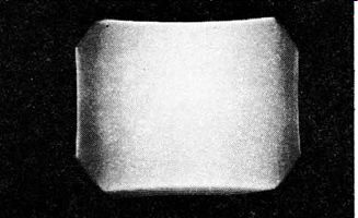
Fig. 7-12. Shaded pin-cushioned raster.
The unfiltered output from a boost-B+ circuit has a high IS, 750 Hz ripple. Boost voltage in some receivers is applied to the crt focusing electrode or first anode, through a filter, with a small electrolytic capacitor. If vertical bars or shaded strips appear in the raster, check with the scope to see if the boost line has a high ac ripple. This is sometimes a baffling problem. The dc voltage measures correctly, and the fact that the electrolytic capacitor might be low in value, thus permitting high-level ripple voltage to modulate the raster, might be overlooked.
Few tv receivers are completely free from raster shading. Owners of receivers are usually tolerant of this condition, unless it becomes quite prominent, as seen in Fig. 7- 12. The raster has reasonably uniform illumination from top to bottom, but is very noticeably shaded from left to right. The trouble stems, therefore, from the horizontal section in the receiver. Waveform checks at each picture-tube electrode will indicate quickly the point at which the spurious ac voltage is entering. Do not forget the high-voltage power supply. An open high-voltage filter capacitor can introduce sufficient ripple into the second-anode supply voltage to shade the raster.
Pincushioning, evident in Fig. 7-12, is not a waveform-based symptom. It merely indicates that the anti-pincushion magnets are not properly adjusted, or that a replacement yoke does not match the picture tube (or vice versa). Consult the receiver service data for correct replacement parts and tubes. If a replacement yoke does not match the horizontal-output transformer (or vice versa), the trouble condition does show up as waveform distortions and/or incorrect amplitudes. Again, refer to the receiver service data for recommended replacement parts.
KEYSTONING
Keystoning as seen in Fig. 7-13 is usually caused by defective vertical-deflection coils in the yoke (see SECTION 8), but this is not always the case. In some receivers, reliance is placed on a single, large electrolytic capacitor in the horizontal section to decouple the horizontal and vertical circuits. When the capacitor is low in value, the heavy sawtooth-current in the horizontal circuits modulates the dc supply to the vertical-sweep circuit, causing a keys toned raster.
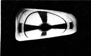
Fig. 7-13. Keystoning is not always caused by yoke trouble.
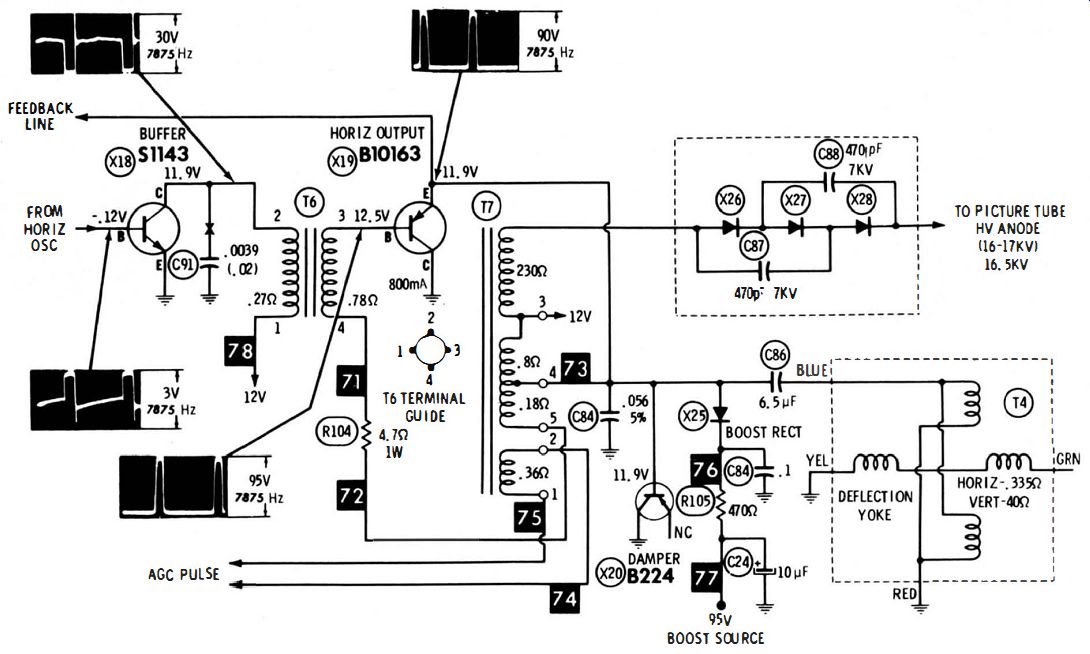
Fig. 7-14.
In that case, a scope check of the common supply line to the horizontal and vertical sections will show a high-amplitude horizontal sawtooth to be present. Again, faulty decoupling can also cause horizontal keystoning by permitting 60-Hz sawtooth ripple to feed into the horizontal system. This is usually less prominent than the vertical keystoning.
SOLID-STATE HORIZONTAL-OUTPUT SYSTEM
The same general principles that apply to electron-tube horizontal sweep systems are found in a solid-state system such as the one shown in Fig. 7-14. The chief distinction is that a solid-state arrangement has lower internal impedances. This means that voltages are comparatively low and that currents are comparatively high. Transistors are normally very long-lived, and if they fail, they tend to do so catastrophically. However, a buffer or output transistor will occasionally develop an abnormal amount of leakage current. Picture symptoms are reduced width and compression on the right-hand side of the screen. A scope test will show reduced amplitudes of the buffer and output waveforms. An audible power-supply hum may also develop, caused by the abnormal current drain.
To summarize, do not make conclusions in troubleshooting the horizontal-sweep section until the key waveforms have been checked. This procedure can often save time as well as needless expense in replacement of normal components.