½-WATT AUDIO AMPLIFIER
This circuit shows a simple three-stage audio amplifier of a type that can be used in an intercom where the speaker is also used as a microphone. The amplifier has a maximum power output of 0.5 watt, with a 5 % distortion at 0.4 watt. The drive requirement for this circuit is 5 mv at 0.4 watt, and the frequency response is from 140 cycles to 2 khz at 0.25 watt.
Courtesy Delco Radio Div., General Motors Corp.
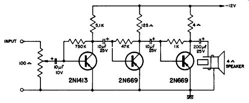
-------- ½-watt amplifier.
½-WATT AUDIO-FREQUENCY AMPLIFIER
The amplifier uses five transistors and a 9-volt source to produce 0.5 watt of audio power. No transformers are used; the frequency response is essentially flat from 95 cycles to 16 khz, and the power gain at 1 khz is 86 db.
There is a 45-ma standby current with zero signal, and for maxi mum power output an input signal of 1.6 mv is required with a distortion of 10% at 1 khz; the input current needed from the battery to provide maximum power output is 90 ma. There is 2 % distortion at 1 khz with an output of 50 mw; the circuit input impedance is 24K.
----------------
Q1-SFT 337
Q2-SFT 353
Q3-SFT 325
Q4-SFT 325
Q5-SFT 325
C1-5 mfd, 6V electrolytic
C2 -100 mfd, 12V electrolytic
C3 -25 mfd, 6V electrolytic
C4 -500 mfd, 3V electrolytic
C1 -50 mfd, 6V electrolytic
C6 -50 mfd, 6V electrolytic
C7-1000 mfd, 6V electrolytic
R1-560K, ½ watt 10%
R2-2.2K, ½ watt 10%
R3-5,6K, ½ watt 10%
R4-1K, ½ watt 10%
R5-820 ohm, ½ watt 10%
R6 -820 ohm,½ watt 10%
R7-100 ohm,½ watt 10%
R8 -100 ohm, 1/2 watt 10%
R9-100 ohm, 1/2 watt 10%
R10-1.5K, ½ watt 10%
R11-82 ohm,½ watt 10%
R12-1.5K, ½ watt 10%
R13-82 ohm, ½ watt 10%
R14-1 ohm,½ watt 10%
R11-1 ohm,½ watt 10%
Speaker-20 ohms impedance
Courtesy Nucleonic Products Co.
-----------
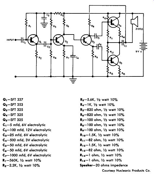
½ watt audio-frequency amplifier.
-----------------
¾-WATT AUDIO AMPLIFIER
This four-transistor amplifier provides a 0.75-watt output and uses a 9-volt source which is split into two 4.5-volt sources as shown.
The frequency response is from 100 cycles to 8 khz, with a maximum power gain of 77 db at 1 khz.
The standby current with no signal input is 1 7 ma, and the input current to provide maximum power output at 1 khz is 120 ma; there is a 10% distortion at this maximum power output. The input impedance to this amplifier is SK.
-----------
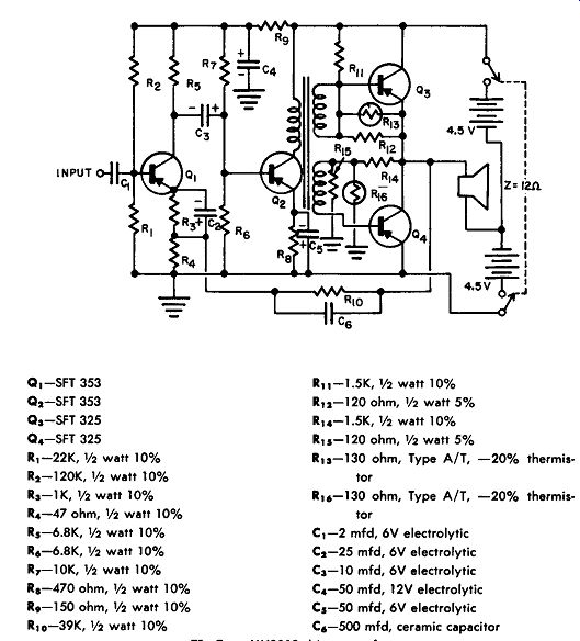
T1-Type MH2O89 driver transformer
Courtesy Nucleonic Products Co.
¼-watt audio amplifier.
-----------------------
1-WATT PHONOGRAPH AMPLIFIER
This circuit shows a complete 1-watt phonograph amplifier using two type T1417 transistors, and one type SC727 power transistor.
A single diode is used to provide half-wave rectification, and the rectified voltage is applied to all three transistors. A bass and treble control, as well as a volume control, are used in the circuit. The out put transformer should have a 720-ohm primary to match the voice coil impedance of the speaker.
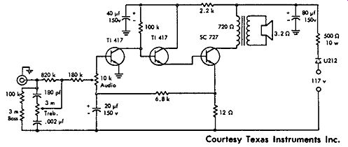
----- 1-watt phonograph amplifier.
1-WATT AUDIO AMPLIFIER
This is a four-transistor 1-watt audio amplifier with a frequency response from 75 cycles to 15 khz and a maximum power output of 1.4 watts. The power supply voltage is 12 volts, and the standby current for zero signal input is 20 ma. The power gain at 1 khz is 78 db. With a 10-mv input and an input current of 16 ma at 1 khz, the distortion is 4 % with maximum power output. There is 2 % distortion at 1 khz with a power output of 250 mw. The transformers are available from Nucleonics Products Co., Los Angeles, California.
-------------
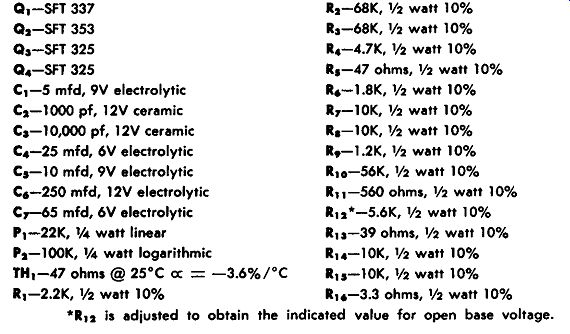
*R12 is adjusted to obtain the indicated value for open base voltage.
--------
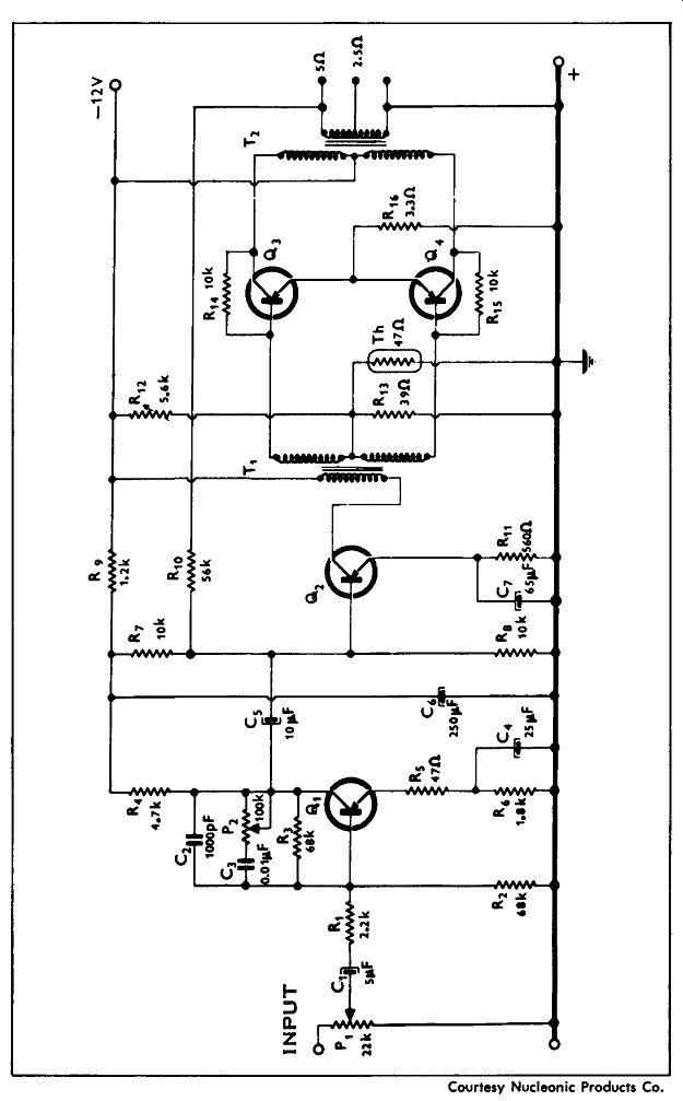
------------- 1-watt audio amplifier.
1.3-WATT AMPLIFIER
This is a three-transistor amplifier using an 18-volt battery supply to produce 1.3 watts of audio power. The frequency response of the amplifier is from 200 cycles to 20 khz, and the power gain at 1 khz is 67 db. The standby current with zero signal input is 15 ma, and the input current at maximum power output is 110 ma. Distortion at 1 khz is 3% with a 375-mw output. The transformer is a special type available from the manufacturer, Nucleonics Products Company, Los Angeles, California.
-----------------
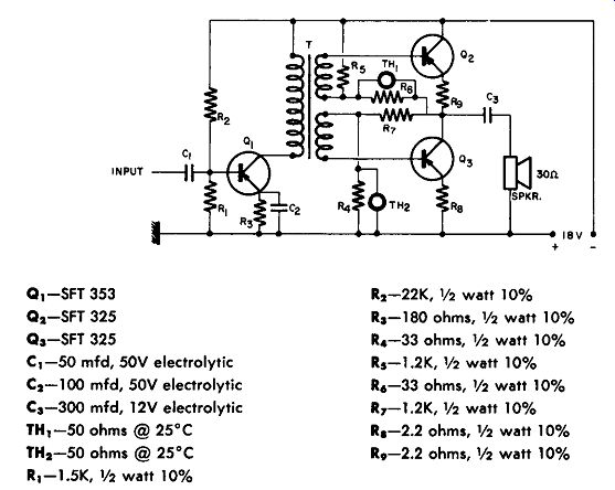
Courtesy Nucleonic Products Co. 1.3-watt amplifier.
------------------------
2-WATT AUDIO AMPLIFIER
This circuit shows a 2-watt audio amplifier using special Amperex transistors types 2N2429, 2N2428, and 2N2431. It consists of a preamplifier stage using a 2N2429, feeding a driver stage using a 2N2428, and two transistors type 2N2431 in the output stage.
This output stage is class B push-pull, using a common emitter resistor (R14) and a negative temperature coefficient resistor (R10) to provide thermal stability. The amplifier operates from a 9-volt supply and can deliver 2 watts at 10% distortion, or 1.55 watts at 4% distortion. Frequency response for this amplifier is flat within 3 db from 60 cycles to 19 khz.

------------19a
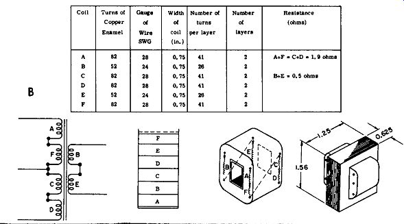
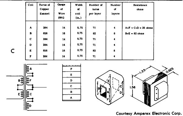
---------- 2-watt audio amplifier.
Part A of the figure is the schematic diagram, part B shows the construction of the output transformer (T1), while part C of the figure shows construction of the interstage transformer (T2). Because of the high gain of these transistors, only three stages of amplification are required to provide enough sensitivity for driving the amplifier from a tuner with the proper impedance. A signal voltage of 6.6 mv is required to produce an output of 1.55 watts, with an input impedance of 7 .6 K. In this circuit 1.2-mv input is required to produce a power output of 50 mw.
By using a 330K resistor in series with the input, it is possible to use this as a phonograph amplifier with a gain which is high enough for a crystal pickup.
1.7-WATT AMPLIFIER
This is a four-transistor 1.7-watt amplifier with a frequency response from 100 hz to 10 khz and a maximum power output of 1. 7 watts with 10% distortion. The power supply voltage is 14 volts, and the power gain of 79 db is obtained at 1 khz. Input impedance is 24K.
--------------
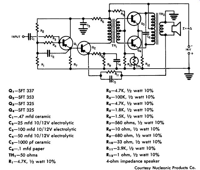
Q1 -SFT 337
Q2-SFT 353
Q3-SFT 325
Q4-SFT 325
C1-.47 mfd ceramic
C2-25 mfd 10/12V electrolytic
C3-100 mfd 10/12V electrolytic C4 -50 mfd 10/12V electrolytic C5-1000 pf ceramic C6-.1 mfd paper TH1-50 ohms R1-4.7K, ½ watt 10% R2 -4.7K, ½ watt 10% R3-100K, ½ watt 10% R4-4.7K, ½ watt 10% R5-1.5K, ½ watt 10% R6 -1.5K, ½ watt 10% R7-560 ohms,½ watt 10% R1 -10 ohm, ½ watt 10% R9-680 ohm, ½ watt 10% R10-33 ohm, ½ watt 10% R11-3,9K, ½ watt 10% R12-1 ohm,½ watt 10% 4-ohm impedance speaker
Courtesy Nucleonic Products Co . 1.7-watt amplifier.
-----------------
2-WATT AUDIO AMPLIFIER
This circuit shows three transistors used in a 2-watt audio amplifier that has 1 % distortion at 1 watt. The drive requirements are 6 mv at 2.0 watts. The frequency response is from 90 hz to 6 khz at 1.0 watt.
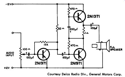
Courtesy Delco Radio Div., General Motors Corp. 2-watt audio amplifier.
2.5-WATT AUDIO AMPLIFIER
This circuit shows a two-transistor audio amplifier of the type that can be used as an intercom. The maximum power output is 2.5 watts with 4% distortion at 1.0 watt. The drive requirements are 3 mv at 1.0 watt, and the frequency response is from 120 cycles to 4 khz at 1.0 watt.

-------------- Courtesy Delco Radio Div., General Motors Corp. 2.5-watt audio amplifier.
2.5-WATT AUDIO AMPLIFIER
This circuit shows a transformer-coupled two-transistor audio amplifier with 2.5 watts of audio output and 6% distortion at 1.0 watt.
The drive requirements are 8 mv at 1.0 watt, and the frequency response is from 40 hz to 14 khz at 1.0 watt.
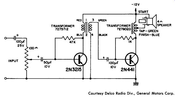
-------------------- Courtesy Delco Radio Div., General Motors Corp. 2.5-watt audio amplifier.
2.5-WATT AUDIO AMPLIFIER
This circuit shows a two-transistor resistance-coupled audio amplifier with 2.5 watts of audio output and 6% distortion at 1.0 watt.
The drive requirements are 6 mv at 1.0 watt. The frequency response is from 100 cycles to 3.5 khz at 1.0 watt.
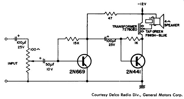
---------------- Courtesy Delco Radio Div., General Motors Corp. 2.5-watt audio amplifier.
2.5-WATT AUDIO AMPLIFIER
This circuit shows a two-transistor transformer-coupled audio amplifier that is suitable for intercom. The output is 2.5 watts, and there is a 5 % harmonic distortion at 0.5 watt. The drive requirements are 5 mv at 0.5 watt; the frequency response is from 60 cycles to 5 khz.
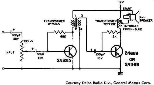
------------- Courtesy Delco Radio Div., General Motors Corp. 2.5-watt audio amplifier.
6-WATT HIGH-FIDELITY AUDIO AMPLIFIER
This high-fidelity amplifier has a frequency response of ± 1.5 db over the frequency range from 30 to 15,000 hz. In this 6-watt amplifier there is 2.5 % h1termodulation distortion, less than 1 % harmonic distortion, and a - 74-db noise level. No transformers are used in this circuit other than in the suggested power supply. Essentially, there are three different portions to the circuit, as shown.
Part A shows the preamplifier stages with two transistors; both are 2Nl 80. The input is a GE reluctance pickup capacitively coupled to the base of the input transistor. Two stages of preamplification are used, and stage A is coupled to stage B, which is the volume and tone control stage. All of these controls are the logarithmic taper type.
The volume control is 2.5K; there is a 50-K treble and a 10-K bass, as shown, with a single 2Nl 80 stage of amplification. Output from stage B is coupled at point Y to the driver of the power-output stage.
The driver is a single 2Nl80 which feeds two transistors; one is a 2Nl 80, and the other is a 2Nl82. A thermistor connected from base to base of these two transistors is used to protect the units from high temperature; output to the 8-ohm voice coil is obtained from a pair of 2N256 transistors. Note that there is direct coupling in this power-output stage between the predriver, the driver pair, and the power output stages. A suggested power supply is shown to provide the required 25 volts de.
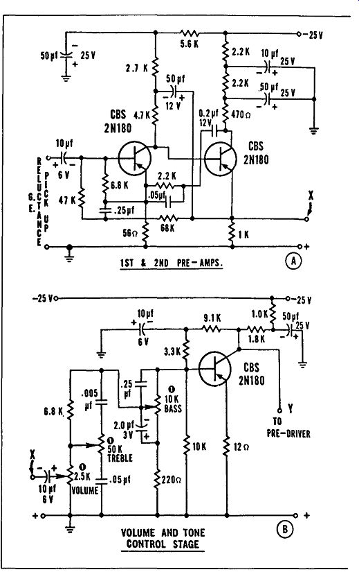
------------- 6-watt high-fi audio amp.
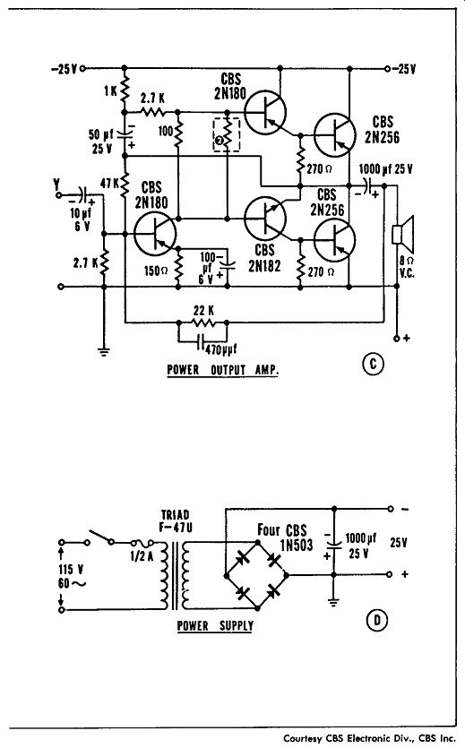
-------------
50-WATT AUDIO AMPLIFIER
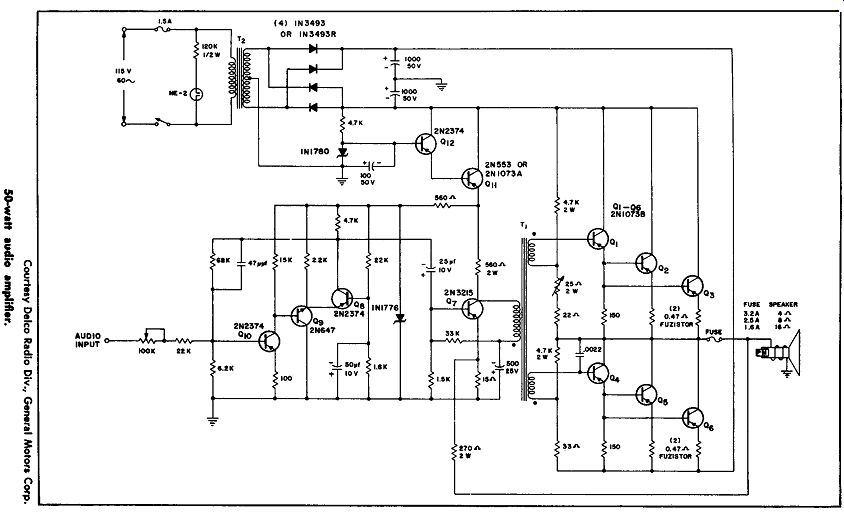
This amplifier produces 50 watts of audio amplification, using 2N1073B transistors in a wide-band low-distortion circuit. The amplifier will provide this power into a speaker with a 4-ohm to 16-ohm load at any frequency in the range from 20 cycles to 20 khz. If required, it is possible to provide up to a 25-volt output to drive electrostatic speakers.
This circuit uses a class-B output stage, with direct coupling to a load being made possible by the dual power supply. The output transistors (Q1 through 0 6 ) are transformer-coupled by means of T1 to transistor Q7, which is a class-A driver. The predriver transistors (Os, 00, and 0 1o) are coupled to the driver stage to provide low distortion and a low-impedance driving source for transistor Q7. There are two independent negative feedback loops. There is 66 db of feedback around the predriver transistor group and also about 20 db of feedback around the driver and output group of transistors.
A power supply of 24 volts regulated by Q11 and Q12 is used to provide the necessary voltage for Q7. A 16-volt zener diode is used to aid the decoupling. A 46-volt power supply which consists of a full-wave rectifier bridge, center tapped to ground and filtered, is employed to power the unit.
Input impedance to this amplifier is 22K, with an output sensitivity of 400 mv for a 50-watt output delivered to 8 ohms. It is possible to increase the input impedance if the 22K series resistor is increased in value.
The power response is ±0.5 db from 20 cycles to 20 khz at 50 watts out into a 4-, 8-, or 16-ohm load. For a 4-ohm load there is less than 1 % intermodulation distortion at 50 watts, and less than 0.5% distortion at 10 watts. The total harmonic distortion and noise for a 4-, 8-, or 16-ohm load is less than 1 % from 20 to 10,000 cycles at 50 watts, and less than 2 % at 20 to 20,000 cycles at 50 watts. The out put impedance is less than 0.5 ohm from 20 cycles to 20,000 cycles.
TRANSFORMER SPECIFICATIONS
T1-Driver Transformer: Core: Allegheny Ludlum #4750 material, E1 75. Approximately ¾ pound, interleaved 1 X 1.
Coil Form: American Molded Products E-33 nylon bobbin (for ¾-inch stack). Coil: Simultaneously wind three #30 and two #26 wires to fill bobbin. (Approximate individual wire length is 50 feet.) Connect the three #30 wires in series-aiding to form primary.
T2 -Power Transformer: Core: Arnold Engineering "Silectron" AA-6. (C-cores.)
Coil Form: .040-inch-thick kraft paper. 1" X 1 ¼." X 1 17 /32" long.
Coil: Primary-378 turns #22. Secondary-2 each 113 turns #21 (bi-fliar).
--------------
AUDIO-OUTPUT STAGE
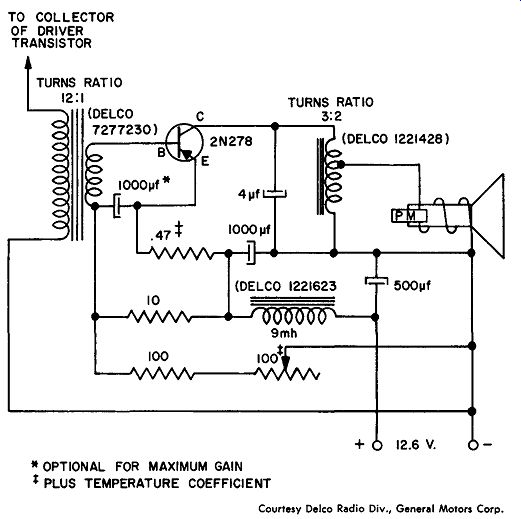
This circuit represents a single-ended audio-output stage similar to that used in an automobile radio. Input from the collector of the driver stage is transformer-coupled. The bias applied to the output transistor depends on the voltage divider made up of the 10-ohm and 100-ohm resistors together with the 100-ohm variable resistor. This variable resistor is set to produce a collector current of 1.05 amperes.
The purpose of the choke and two capacitors is to remove any possibility of interference from the electrical system of the automobile with the amplifier.
---------
* OPTIONAL FOR MAXIMUM GAIN
PLUS TEMPERATURE COEFFICIENT
Courtesy Delco Radio Div., General Motors Corp. Single-ended audio-output stage.
Distortion is less than 10% at 4-watts output. The output transformer matches the 4-ohm speaker to the 11-ohm collector output impedance. It is necessary that a heat sink be used; Delco type 7270725 and type 7281366 are suggested.
This is a single-stage (2N255), transformer-coupled, class-A power amplifier used for audio. This unit is designed to be plugged into the portable radio phone jack for increasing the power output of a personal portable radio to 1 watt.
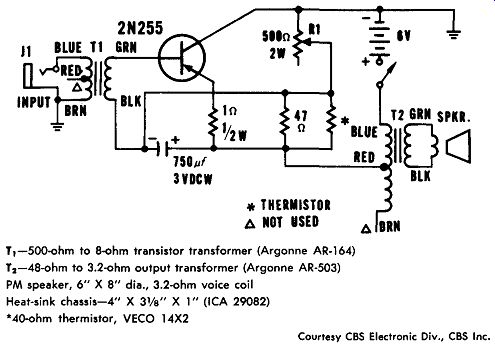
* THERMISTOR; NOT USED T1-500-ohm to 8-ohm transistor transformer (Argonne AR-164)
T2 -48-ohm to 3.2-ohm output transformer (Argonne AR-503)
PM speaker, 6" X 8" dia., 3.2-ohm voice coil Heat-sink chassis-4" X 31/a" X 1" ( ICA 29082)
*40-ohm thermistor, VECO 14X2
Courtesy CBS Electronic Div., CBS Inc. Audio power amplifier.
The input transformer is used to match the output impedance of the receiver to the low input impedance of the power-amplifier transistor, while the output transformer is used to match the power amplifier to the speaker. Variable resistor R1 should be adjusted to provide an emitter current of 0.5 ampere.
LOW-DISTORTION POWER AMPLIFIER
This is a two-stage power amplifier that requires an input of 2.1 amperes at 12.6 volts de from a regulated supply. A 2N109 transistor acts as a driver, and the power output stage is made up of two 2N278 transistors. The circuit is transformer-coupled with an output transformer designed for a 4-, 8-, or 16-ohm load. The input impedance of the amplifier is 6,000 ohms at 400 cycles per second.
The frequency response is flat within 2 db from 60 cycles to 8 khz.
Maximum undistorted output at 400 cycles is 7.5 watts. The maximum power output at 400 cycles is 12 watts, and the total harmonic distortion at 2 watts output at 400 cycles is 0.8%. The power gain is 51.2 db at 8 watts output.
The driver stage has a collector current of 5.5 ma and a 9-volt nominal difference between the collector and emitter. The driver is transformer-coupled to the bases of the 2N278 power transistors, each of which operates at 1.05 amperes of collector current in class A push pull. The thermistor (RT1) provides a negative temperature compensation to limit base current. A 0.5-ohm resistor rated at 10 watts acts as a fuse. Each of the power transistors must have a heat sink (Delco 7278788 or equivalent), and to prevent regenerative feed back, the transformer should be connected as shown in the drawing.
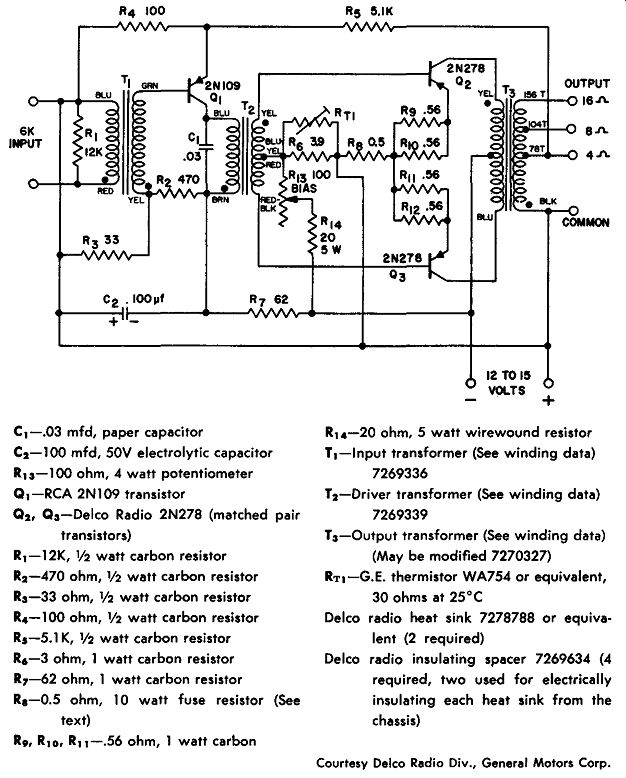
C1-.03 mfd, paper capacitor
C2- 100 mfd, 50V electrolytic capacitor
R4-100 ohm, 4 watt potentiometer
Q1-RCA 2Nl09 transistor
Q2, Q3-Delco Radio 2N278 (matched pair transistors)
R1-12K, ½ watt carbon resistor
R2-470 ohm, 1/2 watt carbon resistor
R3-33 ohm, ½ watt carbon resistor
R4-100 ohm, ½ watt carbon resistor
R5-5.1 K, ½ watt carbon resistor
R6 -3 ohm, 1 watt carbon resistor
R7-62 ohm, 1 watt carbon resistor
R8-0.5 ohm, 10 watt fuse resistor (See text)
R9, R10, R11 -.56 ohm, 1 watt carbon
R14-20 ohm, 5 watt wirewound resistor
T1-lnput transformer (See winding data)
7269336
T2-Driver transformer (See winding data)
7269339
T3-Output transformer (See winding data)
(May be modified 7270327)
RT1-G.E. thermistor WA754 or equivalent, 30 ohms at 25°C Delco radio heat sink 7278788 or equivalent (2 required)
Delco radio insulating spacer 7269634 (4 required, two used for electrically insulating each heat sink from the chassis)
Courtesy Delco Radio Div., General Motors Corp. Low-distortion power amplifier.
PHONOGRAPH AMPLIFIER
This is a lightweight, inexpensive phonograph amplifier using three 2N180 transistors and one 2N255 as the power output. Other transistors may be substituted, as shown in the schematic. This unit will provide about ½ watt of audio power output from a standard crystal pickup, and the current drain is about 500 ma. If desired, a simple power supply can be substituted for the 6-volt battery.
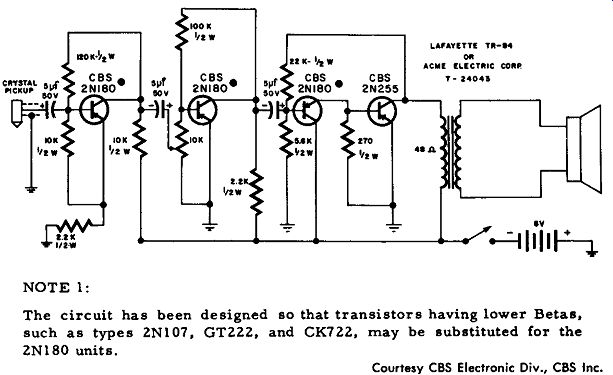
NOTE 1: The circuit has been designed so that transistors having lower Betas, such as types ZN107, GTZZZ, and CK7ZZ, may be substituted for the ZN! 80 units.
Courtesy CBS Electronic Div., CBS Inc. Phonograph amplifier.
15-WATT STEREO AMPLIFIER
This circuit is designed as a stereo amplifier without elaborate circuit devices. The frequency response is reasonably flat from 40 cycles to 15 khz, and 15 watts of power can be obtained from about 80 cycles to beyond 10 khz. Five watts of output can be obtained up to about 20 khz, while more power output can be obtained in the low frequency end by increasing the value of the power-supply filters.
Four transistors are shown; the transistors in the driver stage are direct-coupled. Resistor R3 is used to provide both a-c and d-c feed back. The a-c feedback will lower distortion and the d-c feedback allows a wide variation in the gain of the transistors.
R3 is used for temperature compensation. The collector-to-emitter voltage of 02 should be about 8 volts d-c, and if it is not, resistor R3 should be adjusted. There is no direct current in the input transformer; thus, its size is kept small and the low frequency response is increased. Note that the input transformer is a special type, used to reduce the phase shift and high frequencies, and to allow effective feedback without creating oscillations. The output from this unit is at least 15 watts, into an 8-ohm speaker.
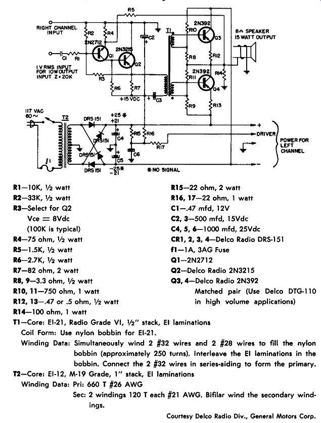
R1-10K, ½ watt
R2-33K, ½ watt R3-Select for Q2 Vee= 8Vdc (100K is typical)
R4-75 ohm, ½ watt R5-1.5K, ½ watt R6-2.7K, ½ watt R7-82 ohm, 2 watt RB, 9-3.3 ohm, ½ watt R10, 11-750 ohm, 1 watt R12, 13-.47 or .5 ohm,½ watt
R14-100 ohm, 1 watt
R15-22 ohm, 2 watt
R16, 17-22 ohm, 1 watt C1-.47 mfd, 12V C2, 3-500 mfd, 15Vdc C4, 5, 6-1000 mfd, 25Vdc CR!, 2, 3, 4-Delco Radio DRS-151 fl-I A, 3AG Fuse Q1-2N2712 Q2-Delco Radio 2N3215 Q3, 4-Delco Radio 2N392
Matched pair (Use Delco DTG-110 in high volume applications)
T1-Core: E1-21, Radio Grade VI, ½" stack, E1 laminations
Coil Form: Use nylon bobbin for E1-21.
Winding Data: Simultaneously wind 2 #32 wires and 2 #28 wires to fill the nylon bobbin (approximately 250 turns). Interleave the E1 laminations in the bobbin. Connect the 2 #32 wires in series-aiding to form the primary.
T2-Core: El-12, M-19 Grade, 1" stack, E1 laminations Winding Data: Pri: 660 T #26 AWG Sec: 2 windings 120 Teach #21 AWG. Bifliar wind the secondary windings.
Courtesy Delco Radio Div., General Motors Corp. 15-watt stereo amplifier.
------------
MULTI-INPUT PRE-AMPLIFIER
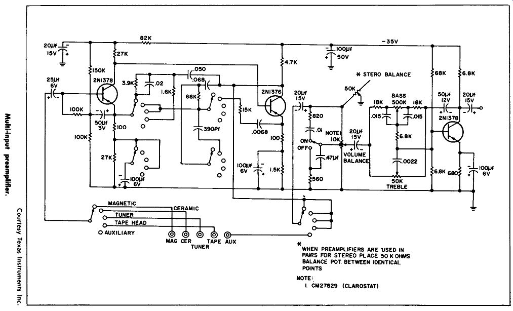
This circuit shows a three-transistor multi-input preamplifier de signed for a magnetic pickup, a ceramic pickup, a tuner input, a tape
head input, and an auxiliary input. The input impedance is 2 megohms at 1 khz, with a rated output of 0.5 volt peak to peak.
For the magnetic-phonograph input, 8 millivolts rms is required; for the ceramic-phonograph input, 100 millivolts rms is required; for the tuner, 130 millivolts rms is required; and for the auxiliary input, 500 millivolts rms is necessary.
A stereo balance control is shown, and when two preamplifiers are used in pairs for stereo work, it is necessary to place 50K ohms in the form of a balance control between these identical points of the two preamplifiers.
PRE-AMPLIFIER
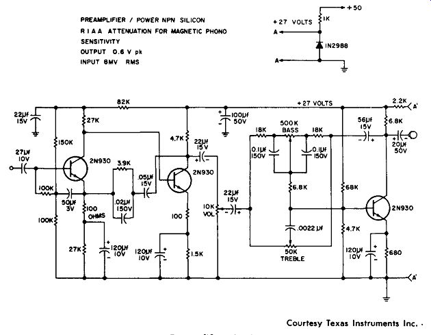
This circuit shows three 2N930 transistors in a preamplifier circuit having a single input designed for a magnetic phonograph pickup. With an input of 8 millivolts (rms) the output of this circuit is 0.6 volt peak to the following audio amplifier. Between the second and third stage there is a 10K volume control, a 50K bass control and a 50K treble control. This circuit is designed to be used with a 27 volt source. A divider network to produce this 27 volts from a 50-volt source is shown.
PREAMPLIFIER / POWER NPN SILICON
ATTENUATION FOR MAGNETIC PHONO SENSITIVITY OUTPUT 0.6 V pk INPUT 8MV AMS
--------------- Courtesy Texas Instruments Inc. Pre-amplifier circuit.
5-WATT PHONO AMPLIFIER
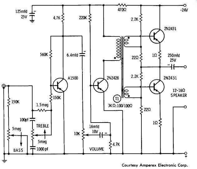
This circuit shows a phonograph amplifier that can produce a 5-watt output with a 0.6-volt input. Transistor types are A-1500, 2N2428, and 2N2431. With a negative 24-volt supply, the amplifier directly drives a speaker with a 12- to 16-ohm impedance. The inter stage transformer (T1) is a special driver-transformer (American Transformer Company No. 202D2 or H & H Coil Company No. 39AJ5). Both a treble and a volume control are provided.
------------- Courtesy Amperex Electronic Corp. 5-watt phono amplifier.
10-WATT CLASS-B AMPLIFIER
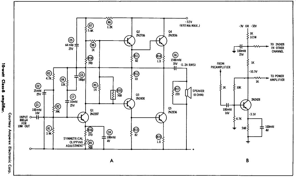
This circuit shows a five-transistor class-B amplifier which provides 10 watts of audio output for an input of 800 microamps. A negative 32-volt supply at 650 milliamps maximum is required. There is no transformer in the circuit, as shown in Fig. A, and this allows a high degree of negative feedback with excellent stability. With some preamplifiers where insufficient input is obtained, an additional pre amplifier, as shown in Fig. B, can be used.
---------------
This circuit, as shown, has a low level of distortion. If this low level of distortion is not required, the components used for feedback (resistor R-4 and capacitor C-3) can be changed to increase the gain.
It is possible that with an increase in gain, the amplifier might not require the preamplifier, depending on the driving source.