240- Mhz 8-WATT TRANSMITIER
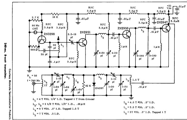
This circuit shows a four-transistor 8-watt continuous-wave transmitter operating at 240 mhz; there is a varactor tripler circuit used for the output stage which triples the 80-mhz signal to 240 Mhz and provides 8 watts of output power. Current drain for this circuit is 0.8 ampere from a 24-volt source.
The most significant part of this circuit is the tripler circuit. The 2N3298 is an 8 -mhz crystal oscillator that has three succeeding stages of amplification, a 2N2951, a 2N2950, and a 2N2947, as shown.
The varactor circuit uses a 1M4387, and the circuit includes three tuned circuits. There is a tuned input, a tuned idler, and a tuned output circuit. The output circuit tuned to 240 Mhz is a double-tuned circuit with capacitive coupling; the idler circuit is tuned to 160 mhz, and it is series tuned. The input circuit is capacitively coupled using double tuning, and it is adjusted for 80 Mhz.
Initial adjustment for the tripler circuit should be made using a 50-ohm, 80-mhz source. The 80-mhz drive should be adjusted for several watts, and each tuned circuit should be adjusted for maximum power output with a grid-dip meter. After the proper output is obtained, the drive source shown in the circuit should be used to feed the varactor or tripler. It will be necessary to retune the circuits for the proper rated power output and greatest circuit efficiency.
--------
160-Mhz C-W TRANSMITIER
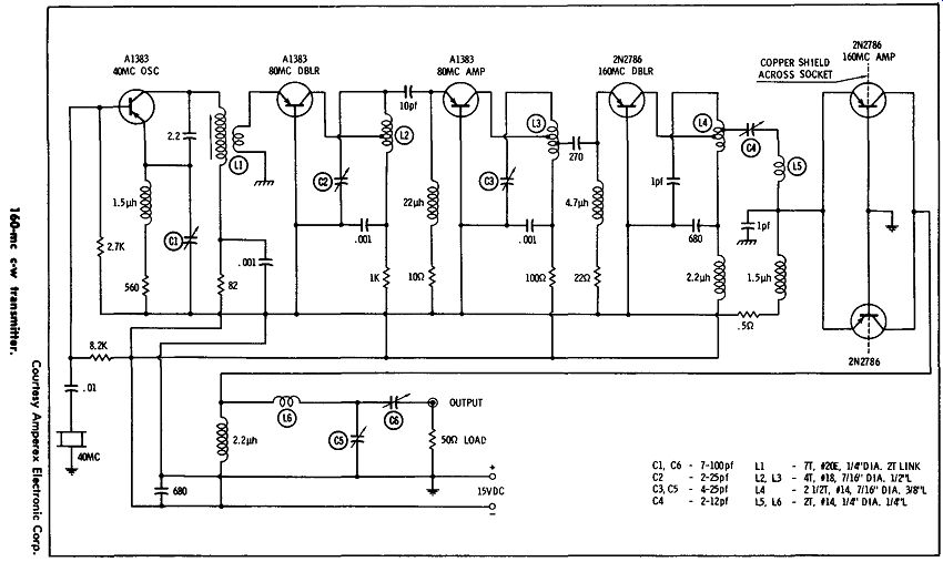
This circuit shows a continuous-wave transmitter operating at 160 mhz, using transistor types A-1383 and 2N2786. The first stage is a 40-mhz oscillator that is crystal controlled, with the crystal connected between base and ground. The output frequency of the crystal is adjusted by means of capacitor C1. The transformer coil (L1) couples the output of the oscillator to the succeeding stage, which is a doubler circuit with an output of 80 Mhz. The doubler tank circuit, consisting of C2 and L2, is tuned to 80 Mhz. The output of the doubler is capacitively fed to the 80 -mhz amplifier. The output of this circuit, which is the tank made up of capacitor Cs and inductor Ls, is coupled to the input of the next stage, a 2N2786, operating as a frequency doubler with an output of 160 Mhz. A push-pull output is used to amplify the 160 -mhz frequency; this stage uses two 2N2786 transistors to provide an output of approximately 1 watt. A 15-volt power source is needed for the power supply.
RESISTORS
1-8.2K 1-2.7K 1-lK 1-82 ohm 1-100 ohm 1-560 ohm 1-22 ohm 1-10 ohm 1-0.5 ohm
R-F CHOKES
2-1.5 ,uh 1-22 ,uh 1-4.7 ,uh 2-2.2 ,uh
FIXED CAPACITORS
4-.001 pf
2-1 pf 1-2.2 pf 1-10 pf 1-270 pf 2-680 pf
VARIABLE CAPACITORS
1-7-100 pf (Arco 423)
4-2-25 pf (E. F. Johnson)
1-7-100 pf (Hammarlund)
MISC.
1-3rd overtone 40 -mhz crystal 1-¼"-dia. ceramic coil form 2-5-way binding posts 3-Heat sinks (Thermolly #2215B) 6-Transistor sockets
-----------
170-Mhz TRANSMITTER
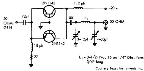
This circuit shows a 170-mhz transmitter-output stage using two 2Nl 142 transistors. A 20-volt supply is used, and the two transistors are connected in parallel. The transistors operate in a common-base circuit as class-C amplifiers; the output circuit is a pi network which provides a 50-ohm output to the antenna. Input to this output stage is 50 ohms, and the power gain is about 10 db.
----------- Courtesy Texas Instruments Inc. 170-mhz transmitter.
120-Mhz AIRCRAFT TRANSMITTER
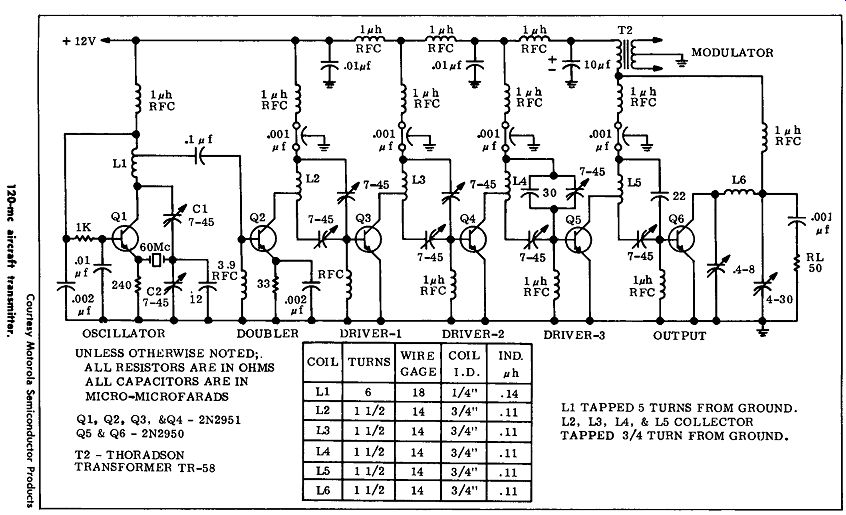
This circuit shows a six-transistor 120-megacycle transmitter using transistor type 2N2950 in the final stages, and type 2N2951 in the other four stages. The circuit consists of an oscillator operating at 60 megacycles, a doubler followed by three driver stages in series, and an output stage. This circuit will provide 1.5 watts output at 120 megacycles into a 50-ohm load. Total current drain is about 370 milliamps.
The oscillator stage is a 60-megacycle crystal-controlled oscillator operated in a series mode, with emitter feedback provided. Q2 obtains its driving power by tapping oscillator coil L1 as shown. Three stages of amplification are required to increase the power level to that needed by the driver. The transistor ( Q2) also functions as a doubler.
Collector modulation is used in the driver stage; this is necessary to obtain 100% modulation in the output stage of the transmitter.
The output stage is collector-modulated from a 12-volt source. Collector modulation is used to obtain the lowest envelope distortion from 100% modulation. The antenna load is the 50-ohm resistor shown as RL in the output stage. A standard modulation transformer is used in the audio-amplifier modulated circuit which feeds the r-f section of the transmitter.
------------
-----------
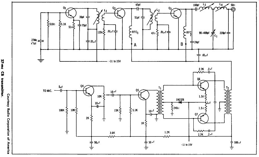
27-Mhz CB TRANSMITIER
This is a 5-watt Citizens band transmitter using seven transistors.
The RCA types 40080, 40081, and 40082 are silicon planar transistors used in the radio-frequency section of the transmitter. This transmitter is designed to be used with a 12-volt system so that it can be operated directly from an automobile storage battery.
The r-f section has three stages-an oscillator, a driver, and a final power amplifier. To obtain 100% modulation both the driver and power amplifiers are modulated. Two class-A amplifier stages driving a class-AB push-pull modulator are used in the audio sections of this transmitter.
The oscillator is a crystal-controlled stage using a 40080 transistor in a Colpitts circuit; frequency stability is within the 0.005% allowed by the FCC. This oscillator provides a minimum of 100 mw of power using a 12-volt source.
The oscillator feeds a driver stage which uses an RCA 40081 in a common-emitter class-C stage that is modulated in the collector circuit. This driver can provide a minimum of 400 mw of power using a heat sink. An RCA 40082 is used as the power amplifier operating in class C in a common-emitter circuit with the modulation in the collector circuit.
The transmitter will provide about 4 watts of power output at 100% modulation with a 12-volt collector supply, and about 4 watts of output with a 13.5 volt collector supply.
C1-ARCO #429 or equiv.
Q1-RCA 40080
Q2-RCA 40081
Q,, 1-RCA 2N591
Q7-RCA 2N301
T1-2.5K:200 ohm C.T.
Q8-RCA 40082
T2-100 ohm
C.T.:30 ohm
L1-14t:3t #22 wire ¼" CTC coil form with "green dot" core 0.75-1.2 hy
Q = 100
L2-14t:2-3/4t #22 wire¼" CTC coil form with "green dot" core 0.75-1.2 hy
Q = 100
la-llt #22 wire¼" CTC coil form with "green dot" core 0.5-0.9 hy
Q = 120
L,-7t #22 wire ¼" CTC coil form with "green dot" core 0.21-0.34 hy
Q = 140
RFC,, 2-15 hy Miller #4624 or equiv.
C-W TRANSMITIER
This circuit shows a low-power c-w transmitter with a variable frequency oscillator operating in the 80-meter amateur band with approximately 100 milliwatts power output. A 12-volt source providing about 12 milliamperes of current is required. Transistor 2N2711 is used as a variable-frequency oscillator, with a type 2N2711 or 2N2712 used as the power-output stage. A key is shown for transmitting the c-w output.
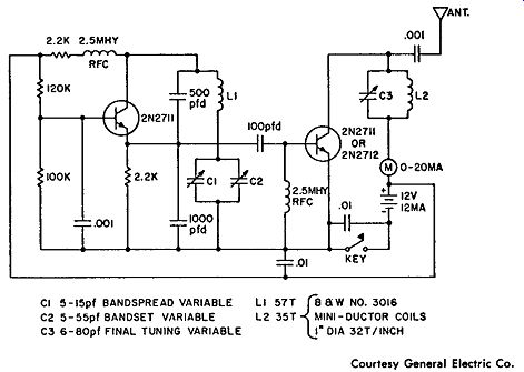
------------- Courtesy General Electric Co. C-w transmitter.
20-WATT MARINE TRANSMITIER
This circuit shows a 20-watt marine transmitter operating on a frequency of 2.18 megacycles. Marine radio equipment of the radio telephone type has transmitter power ratings ( the d-c power required by the transmitter final) that vary from 15 watts up to several hundred watts in the frequency band from 2 to 3 megacycles. This transmitter uses three transistors in the r-f portion of the circuit as shown; the transistors are used in an output, a driver, and an oscillator stage.
A 12-volt supply is used for this transmitter.
The transmitter will deliver 10 watts of carrier output into a 50 ohm load with an efficiency of about 48%. The modulation power required is about 7 watts at 10 ohms. A standard modulation transformer which will provide 10 ohms of secondary impedance into this circuit is used.
A crystal-controlled transmitter is used with direct crystal drive at 2.18 megacycles. The output stage is a 2N2832 which delivers the 10 watts of output power into a 50-ohm load; this is the approximate load of a 9-foot whip antenna which is bottom-loaded. Drive power for the output stage is about 1 watt, and the input impedance of this stage is 5 ohms. A special transformer, as shown, is used to provide this impedance transformation from the driver stage, which is a type 2Nll32. The driver stage provides about 1 watt of carrier power to drive the output stage, and the required emitter loading for this power level is about 72 ohms.
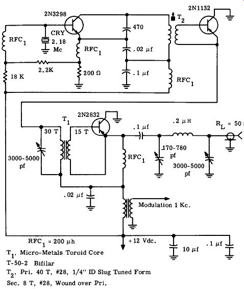
----------------- Courtesy Motorola Semiconductor Products. 20-watt marine transmitter.
SUPER-REGENERATIVE 27-Mhz RECEIVER
This circuit shows a four-transistor super-regenerative receiver for operation in the 27-megacycle band. It is designed to be used for speech reception or for relay operation in remote control.
The regenerative detector uses a type 2N2926 transistor. This stage is followed by two stages of amplification, using type 2N2926 transistors. When the receiver is used for reception, the output is taken from the 0.001-mfd capacitor. If it is to be used for remote-control operation, the additional stage using the 2N2926 is used together with a relay to control the remote circuit. A power source of 4.8 volts is required.
RECEIVER TO THIS POINT IF FOR RELAY OPERATION IN REMOTE CONTROL ONLY SPEECH RECEPTION IS OESIREO-i APPLICATIONS ADO THIS RELAY CIRCUIT
L1 - IS TURNS •24 AWG TAPPED AT 6 TURNS, PROPORTIONED AS SHOWN 6 TURNS/9 TURNS ON CTC #SPC11-4L (CAMBRIDGE THERMIONICS CORPORATION )
L2· 180 TURNS AWG ON FERROXCUOE 1408-FIO BOBBIN, IN 1408-PICIO· 385 CUPCORE, HELO BY 1408 BRACKET ASSEMBLY. (FERROXCUOE CORPORATION OF AMERICA, SAUGERTIES, NEW YORK) RELAY - OMEGA SALES HR3CIO REED RELAY RFC· 22,.HEI.RY DELAVAN TYPE •1537-44 (DELAVAN ELECTRIC CORPORATION, 270 QUAKER ROAD, EAST AURORA, NEW YORK)
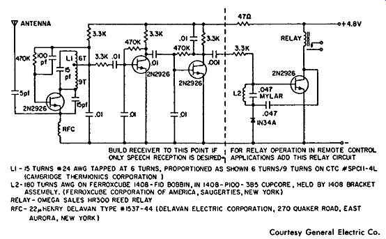
------------------ Courtesy General Electric Co. Super-regenerative 27-mhz receiver.
30-Mhz SINGLE-SIDEBAND TRANSMITIER
This circuit shows a suggested layout for a three-transistor transmitter operating in single-sideband operation at 30 megacycles. Transistor types 2N3295, 2N3296, and 3N3297 are used in the circuit.
Peak envelope power is 10 watts, and the overall power gain is about 35 db. Current feedback for stability is used in the first two stages by using resistors without bypass capacitors in the emitters. The circuit is a linear amplifier for 30-megacycle operation in single sideband, and it requires a driver with a 50-ohm input to transformer T-1, which feeds transistor 2N3295.
In testing this circuit, the odd-order distortion products measured on a two-tone test were greater than 30 db down from reference level.
It is necessary to obtain the utmost in linear operation for a transmitter of this type. This driving-source impedance is obtained in this circuit by using toroid transformers with a high amount of coupling.
Transformer T-1 provides a four-to-tone step-up of the 50-ohm out put from the exciter; T-2 steps up the 20-ohm input resistance of the 2N2950 to the 180 ohms required for the collector loading of the 2N2951. A three-to-one turns ratio is used. A resistor of 2K across the primary of transformer T-2 is used to obtain the maximum base driving 220-ohm impedance for the 2N2950.
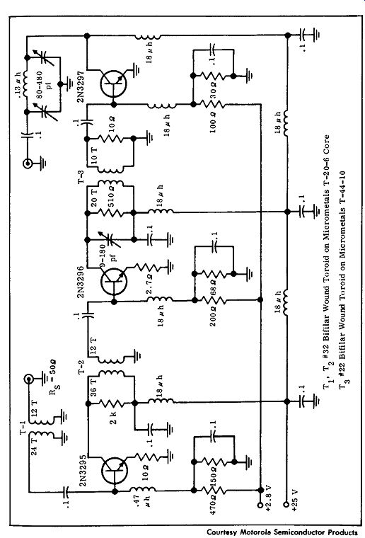
------------ Courtesy Motorola Semiconductor Products 30 -mhz single-sideband transmitter.
------------
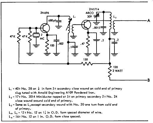
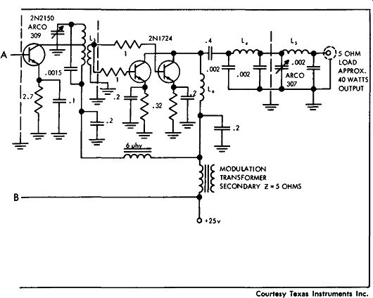
L, - 40 t No. 28 on l in form 5 t secondary close wound on cold end of primary slug tuned with Arnold Engineering Al09 Powdered Iron.
L1 -17t No. 3014 Miniductor tapped at 51 on primary secondary 2t No. 24 close wound around cold end of primary.
L, - Some as L, except secondary wound with No. 20 one turn from cold end of primary.
L,, Ls - 12 t No. 12 on ll in 0. D. form spaced diameter of wire.
l 6 - 161 No. 12 on l in. O.D. form close spaced.
40-watt marine transmitter.
--------------
40-WATT MARINE TRANSMITTER
This circuit shows five transistors in a 40-watt, 2-megacycle marine transmitter. A 2N696 is used as a local oscillator feeding the 2N1714 amplifier, which in turn feeds the 2N2150 driver. A pair of 2Nl 724 transistors are used as the output stage, and modulation is applied to both the driver and the output stages to obtain 80% modulation.
A transformer with a secondary impedance of 5 ohms is necessary for this modulation transformer. Note that separate base- and emitter bias resistors are used in the output stages so that a slight mismatch in the characteristics of the two transistors will not affect the operation of the circuit. There is a double pi network for antenna matching and harmonic suppression; working into a 5-ohm load, there is approximately a 40-watt output.
AM TUNER
This circuit shows a very simple two-transistor a-m tuner using type 2N169 transistors and a 12-volt source. A loopstick is used for the antenna and, if desired, an external antenna can be connected.
A 1N34A is used as the detector, and the output from the jack goes to the associated audio amplifier.
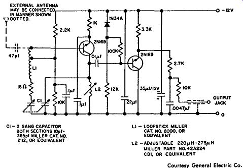
-------------- Courtesy General Electric Co. A-m tuner.
--------------
150-Mhz FM TRANSMITTER
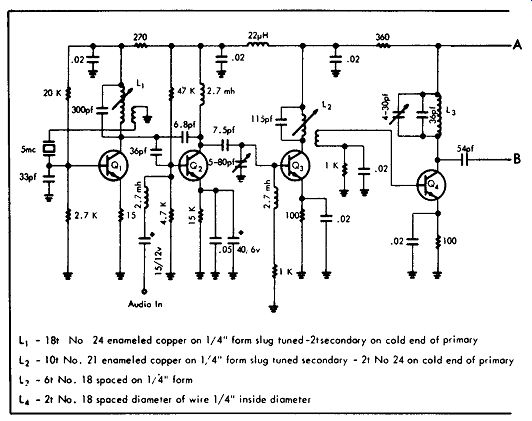
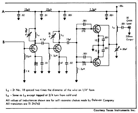
This circuit shows an eight-transistor fm transmitter operating at a frequency of 150 Mhz with 250 mw output; all of the transistors are type TI2N743.
As shown, transistor Q1 is the crystal oscillator operating at 5 mhz, and transistor 02 is a phase modulator. This is followed by three triplers, which are transistors Q3, Q4, and Q1,. The output of transistor Q3 is 15 mhz, the output of transistor Q4 is 45 mhz, and the output of transistor Q5 is 135 Mhz. This assumes a crystal oscillator of 5 mhz, while actually the crystal oscillator is somewhat higher in frequency.
The oscillator ( Q1 ) operates in a common-emitter circuit, with feedback through the crystal; the output is coupled to the base of the phase modulator. The audio input, which is used for phase modulation, is fed through a choke; the output of the phase modulator is coupled to the base of the first tripler. The output of Q3 is tuned to the third harmonic of the crystal oscillator for a tripling action.
Where a 5.5 -mhz crystal is used, the tank circuit would be tuned to 16.5 mhz, and the output of the first tripler is coupled to Q4, the second tripler. The output from the second tripler is 49.5 Mhz.
The 49.5 -mhz frequency is again tripled by transistor Q5, whose output is tuned to 148.5 Mhz. This output is fed to the buffer-driver stage (Q6). The collector tank circuit of Q6 is tuned to 148.5 mhz, and the output from the buffer is coupled to the bases of the two units
Q1 and Q5, which are in parallel for the output. Separate bias and emitter resistors are used in the output stage to provide a balance between the two units.
Except for transistors Q1 and Q2, each of these stages is self-biased and operates as class C. This transmitter can provide 5 khz of deviation about the carrier frequency, with a power output of 250 mw.
FM WIRELESS TRANSMITTER
This circuit shows the use of a tunnel diode in a f-m wireless short range transmitter. As designed, the circuit will operate at a range of approximately 200 yards when it is used with a sensitive commercial f-m receiver.
The frequency of operation is from 96 to 110 Mhz. The antenna length is approximately 25 inches; a 1.34-volt mercury cell is used as the power source. A PM speaker or microphone can be used for the input, which is amplified by the 2Nl 88A transistor that, in turn, modulates the tunnel diode.
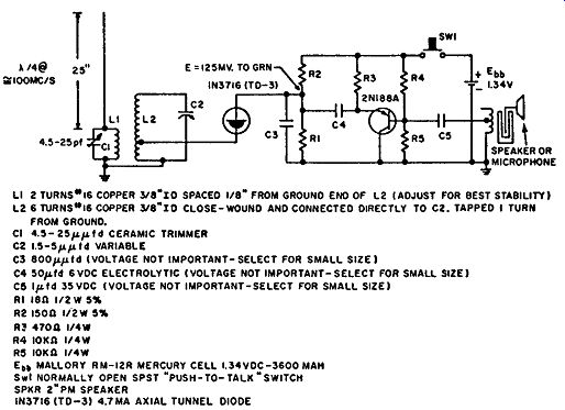
------------- FM wireless transmitter. Courtesy General Electric Co.
27-Mhz CITIZENS BAND TRANSMITTER
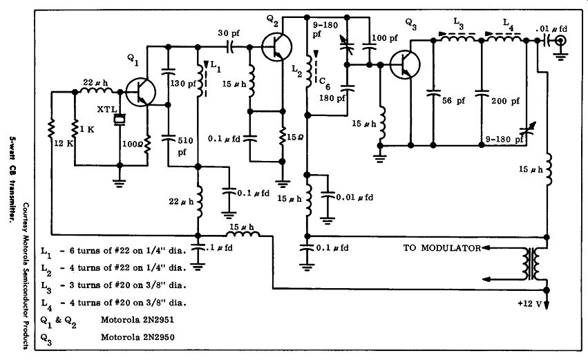
This circuit shows a three-transistor Citizens band transmitter operating with a power output of 5 watts. The audio portion of the circuit is not shown; it is a standard audio amplifier which becomes a modulator for the transmitter. A 2N2950 transistor is used as the transmitter final stage. It provides a power output of greater than 2 watts unmodulated, and 3.2 watts modulated with a single transistor. This power transistor uses a stud mount with isolated leads so that it can be mounted directly on the chassis.
A 2N2951 transistor is used as the crystal oscillator in this circuit; it feeds a second 2N2951 transistor operating as the driver. An audio modulating impedance of 39 ohms is required by the circuit; therefore the transformer that is chosen must match the modulator and provide an impedance of 39 ohms in series with the 12-volt supply.
----------
----------
FM TUNER
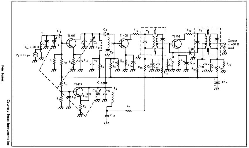
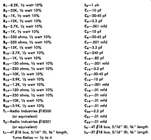
This circuit shows an f-m tuner using transistor types TI 407, TI 408, and TI 409. With an input voltage of 10 microvolts, the out put voltage will be 19 millivolts, which is a power gain of 54 db. At 98 megacycles this circuit has an image rejection of 50 db. A 12-volt source is used.
--------
FM TUNER
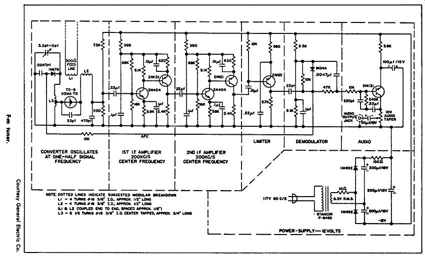
This circuit shows a solid-state f-m tuner with some unique features. The unit is broken down into seven modules; the first module is an oscillator-converter which oscillates at one half of the signal frequency, using a tunnel diode type TD-9. The output from this oscillator-converter to the first i-f module is 200 khz. The first i-f amplifier uses transistors types 2N404 and 2Nl 121, as indicated; the second i-f module, operating at the same center frequency, uses the same type transistors as the first i-f stage.
------------
The limiter uses a type 2N1121 transistor as a single-stage limiter feeding the demodulator, a 1N34A diode. The output from the de modulator is fed to the audio module which uses a type 2Nl 121 transistor as an audio amplifier to provide an audio output to the necessary amplifier. The power-supply module provides 12 volts from a standard a-c line.
1-WATT 27-Mhz TRANSMITTER
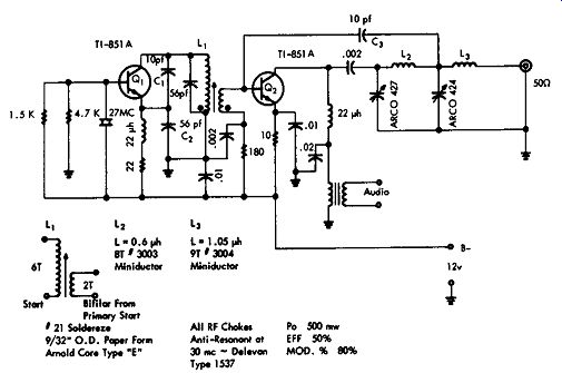
This circuit shows a 27-magacycle Citizens band transmitter operating with a d-c power input to the final of 1 watt with an r-f power output of 500 milliwatts. This circuit can be considered typical of a 1-watt 27-megacycle unit; it consists of a crystal-controlled oscillator and a modulated power amplifier.
Transistor Q1. a TI851 A, is operated as a common-base stage, with the base being grounded only at the crystal frequency. Collector-to emitter feedback is through capacitor C1. and the feedback depends on the ratio between capacitor C2 and capacitor C1.
A choke, which is self-resonant at 27 mhz, is placed in series with the emitter resistor to keep it from being at ground. The oscillator provides approximately 150 mw output power coupled by means of inductor L1 to the output stage ( Q2), which is a TI851 A operating as a class-C amplifier. Collector modulation is applied through the modulation transformer, and about 500 mw of audio power is required.
The power output is 500 mw with a modulation percentage of 80%. The characteristics of the modulation transformer depend in part on the modulator used with this transmitter.
--------------- Type 1537 Courtesy Texas Instruments Inc. 1-watt, 27 -mhz transmitter.
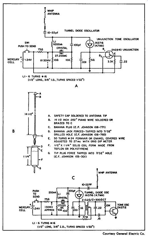
-------------- Ultralow-powered transmitter.
ULTRALOW-POWERED TRANSMITTERS
The tunnel diode can be used to provide a low power source of radio-frequency energy, as in a remote-control transmitter for operating garage doors or toys. Voice modulation is also possible, as shown in the following circuits.
Fig. A shows a crystal-controlled transmitter operating at 27 .255 Mhz. A 1N3716 unijunction tone oscillator is used to modulate a miniature transmitter for remote control of a garage-door opening mechanism. The type 2N2840 unijunction is used as an audio oscillator to modulate the tunnel-diode type 1N3716 oscillator. When the switch is closed, the mercury cell activates the circuit, and a low powered modulated r-f signal is produced. Fig. B shows the suggested type of antenna. Fig. C shows a different type of low-powered transmitter. A 2N2712 silicon transistor used as a Hartley oscillator modulates the tunnel-diode oscillator. The same type of antenna as used in Fig. A is suggested.
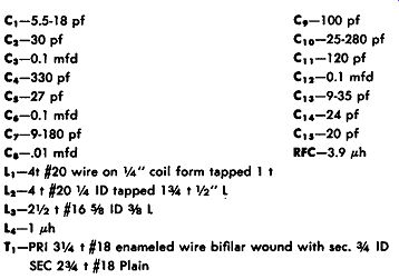
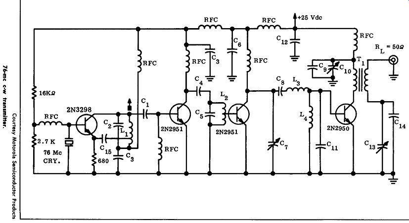
76-Mhz 2-WATT TRANSMITTER
This circuit shows a four-transistor transmitter operating as a c-w unit on 7 6 megacycles. A 2-watt carrier output is obtained by using a 25-volt supply; the output stage draws 145 milliamps with a collector efficiency of 55%. The oscillator and driver circuits have a total current drain of 21 milliamps.
A 2N3298 is used as a crystal-controlled oscillator which feeds a buffer amplifier using a 2N2951. The buffer amplifier, in turn, feeds the driver, a second 2N2951, which feeds the single output stage.
The output stage uses a 2N2950 with an output impedance, through the transformer, of 50 ohms.
---------------
----------------
-----------------
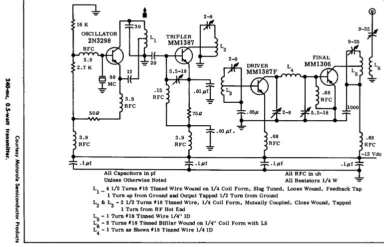
240-Mhz 0.5-WATT TRANSMITTER
This circuit shows a four-stage transmitter operating at 240 Mhz from a 12-volt source; the carrier power output is 0.5 watt. The oscillator is type 2N3298 in a common-base Hartley circuit, with feed back obtained from a tap on coil L1. This oscillator produces about 15 mw of power at 80 Mhz to the next stage.
The succeeding stage is a type MMl 387 transistor that operates as a tripler. This stage provides 3 db of gain and 30 mw of output at 240 Mhz. The collector network in this case is critical, and it is double tuned, with the output circuit tuned to 240 Mhz.
The tripler is the next stage, which is the driver, an MMl 387F transistor; power output of this stage is about 150 mw. The final stage uses an MM1306 transistor; it is zero biased and operates class C. Power output is 0.5 watt or more with a total drain of 180 ma from a 12-volt source.
5-WATT CITIZENS BAND TRANSMITTER
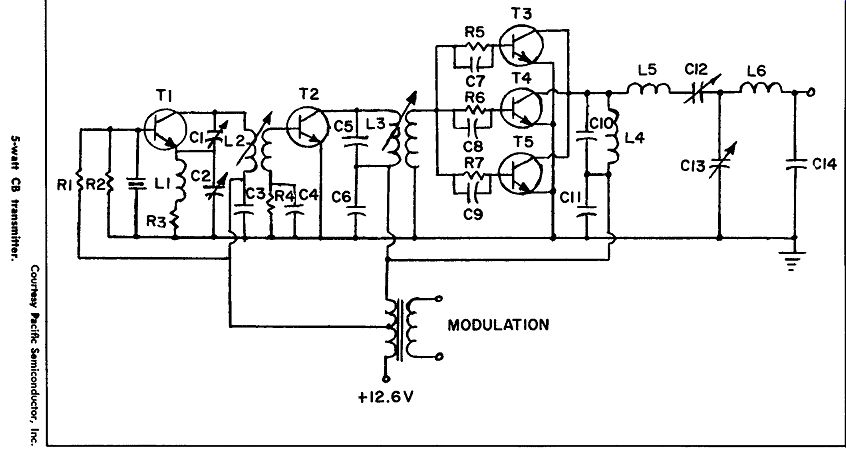
This circuit shows five transistors in a 5-watt Citizens band transmitter where the final power amplifier is a type PT888. Because three of these transistors are used in parallel in the final stage, very low impedance levels are present in this particular stage, and a careful layout is required. These transistors should be mounted with their collectors and emitters tied together with the shortest possible lead length. The individual transistors do not have to be matched as long as units of the same type are used; individual base resistors are used to minimize the variations between transistors. A 12.6-volt supply is used.
The modulation characteristics are improved by modulating the driver transistor as well as the power output stages.
R1-3600 ohm,½ watt
R2 -510 ohm,½ watt
R3-51 ohm, ½ watt
R,, Rs, R6, R7- l 20 ohm, ½ watt
C1-ARCO 404 C2 -ARCO 425 C3 , C4 , C6 , C11 -.005 mfd ceramic disc C5-68 pf, silver mica C7, C1 , C9 -.002 mfd ceramic disc C10-100 pf silver mica C12, Cu-ARCO 429 C15-200 pf silver mica L1-50 µh choke Miller J 300-50 L 2-12 t Pri, 3 I Sec-#24 enameled wire on Cambridge thermionic form SPC-2 J-4l L 3-7 t Pri, 3 t Sec -#20 enameled wire on Cambridge thermionic form 2270-4 L 4 -4 t #20 enameled wire on Cambridge thermionic form SPC-2-J-2l L 5-7 I #20 enameled wire on Cambridge thermionic form 2271-4 L 6-5 I #20 enameled wire on Cambridge thermionic form 2271-4 T 1-PT886, T 2 -PT887 Ti, T,, Ts-PT888
----------------
----------------
20-watt marine transmitter.
20-WATT MARINE TRANSMITTER
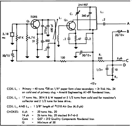
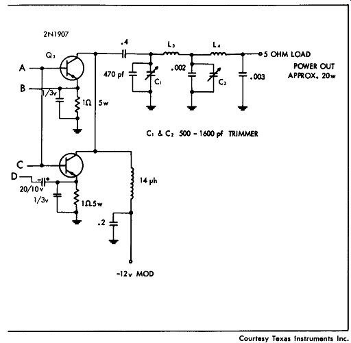
This circuit shows a 2-megacycle marine transmitter with a power output of about 20 watts. The crystal-controlled oscillator is a type TI395, the buffer-driver stage uses a type 2N1907, and two 2N1 907's are used in parallel as the output. A 12-volt supply is used.
Only the final two stages are being modulated. These output stages have a small forward bias applied by resistors R1 and R2. However, the base to emitter diodes will rectify the excitation when this stage is driven, and the resulting current flow produces the reverse bias required for class-C operation.
A double pi output network is used for antenna mixing and harmonic suppression. Working into a 5-ohm load, the power output is about 20 watts with 90% modulation.
1-WATT CITIZENS BAND TRANSMITTER
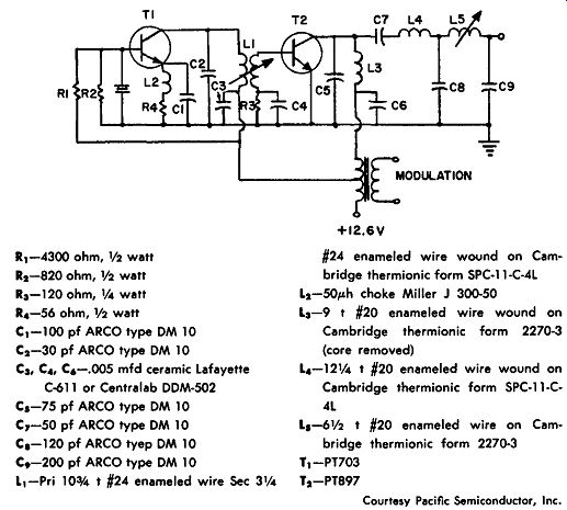
This figure shows a two-transistor Citizens band transmitter with a power output of 1 watt; the transistor types that are used are PT703 and PT897.
The crystal circuit uses a series-mode crystal with a common-base Colpitts circuit where capacitors C1 and C2 determine the feedback.
The oscillator transistor can be the PT703 as shown, or the PT886 which can provide a higher power output.
The crystal oscillator is inductively coupled to the final stage or power amplifier, and the collector circuit is parallel tuned. The power source is 12.6 volts through the standard modulation transformer having a center-tapped secondary. The primary of the modulation transformer is driven by the audio amplifier or modulator.
1 1-4300 ohm,½ watt
12-820 ohm, ½ watt
Ra-120 ohm, 1/4 watt
14 -56 ohm, ½ watt C1-100 pf ARCO type OM 10 C2-30 pf ARCO type OM 10 Ca, C4, C6 -.005 mfd ceramic Lafayette C-611 or Centralab OOM-502 Cs-75 pf ARCO type OM 10 C,-50 pf ARCO type OM 10 Ca-120 pf ARCO type OM 10 c.-200 pf ARCO type OM 10 11-Pri lOo/4 t #24 enameled wire Sec 3¼
#24 enameled wire wound on Cambridge thermionic form SPC-11-C-4L L 2-50µh choke Miller J 300-50 La-9 t #20 enameled wire wound on Cambridge thermionic form 2270-3 (core removed)
14-12¼ t #20 enameled wire wound on Cambridge thermionic form SPC-11-C 4L Ls-6½ t #20 enameled wire on Cam bridge thermionic form 2270-3 T1-PT703 T2-PT897
-------------
Courtesy Pacific Semiconductor, Inc. 1-watt CB transmitter.
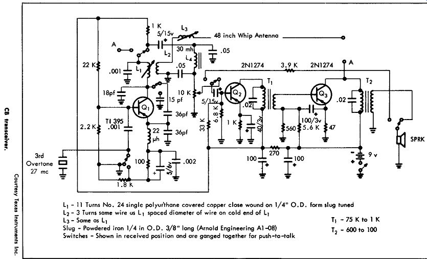
CITIZENS BAND TRANSCEIVER
This circuit shows a three-transistor Citizens band combination transmitter and receiver. This circuit is designed to be used in the license-free type of operation in the 27-megacycle Citizens band.
Transistor Q1, a TI395, operates both as a crystal-controlled 100 milliwatt modulated power oscillator in the transmitting mode, and as a super-regenerative detector in the receiver mode. Transistor type 2N1274 is used for both transistor Q2 and transistor Q3. These are the audio sections of the transceiver, and in the receiving mode they are used as an audio driver and an output stage. In the transmit mode they are used as an audio driver in a modulator. The speaker can be used either as a microphone to transmit, or as a speaker to receive.
This unit provides an audio power output of 35 mw as a receiver; it has a quench frequency in the receiving mode of 200 khz, and the sensitivity is about 3 microvolts. The d-c power input for transmitting is 100 milliwatts, while the r-f power output for transmitting is 30 milliwatts.
-------------------
------------------
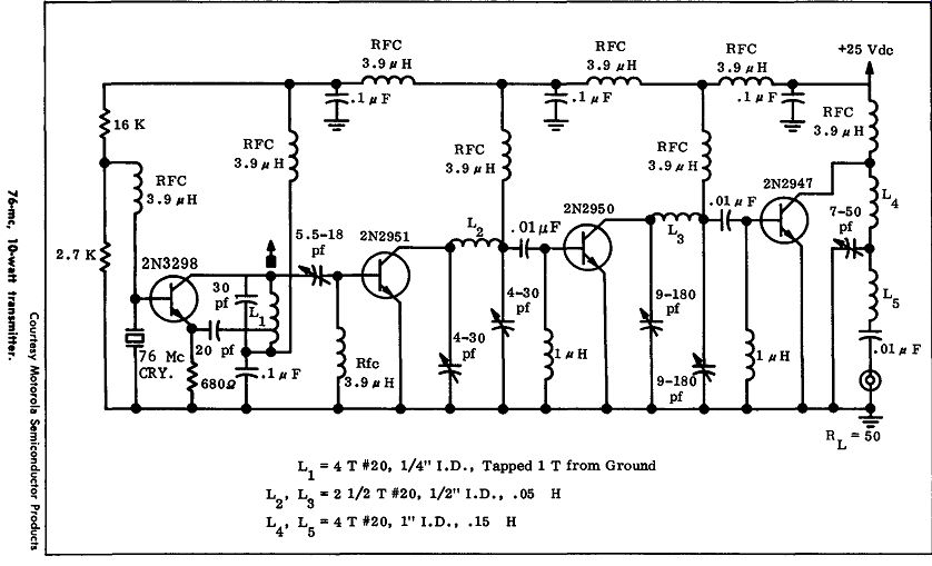
76-Mhz 10-WATT TRANSFORMER
This circuit, with four transistors, is a 76-megacycle c-w transmitter operating with a power of 10 watts using a 25-volt supply.
Following the 2N3298 crystal amplifier is a buffer amplifier, a 2N2951, which feeds a driver stage, a 2N2950. The output from the driver is coupled to the power output stage, which uses a 2N294 7 and provides an output impedance of 50 ohms.
The output stage draws 600 milliamps with a 66% collector efficiency, while the driver stages have a total current drain of 166 milliamps. Total input power required for this circuit is 6 milliwatts.
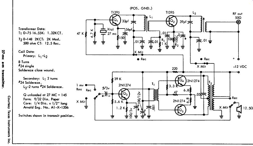
27-Mhz TRANSMITTER
This circuit shows a 27-megacycle transmitter designed for amplitude modulation. It uses a positive-ground power supply. This circuit can provide an input power of 100 mw, and it is shown as a complete transmitter, including the modulating stage. Note that the modulator, as shown, can also be used for the receiver portion of a transmitter-receiver combination. The switches are shown in the transmit position. Q1 is a crystal-controlled oscillator that is transformer-coupled to the power transistor output stage. Output bias is obtained from rectification of the signal by the base-to-emitter diode (Q2). The d-c input to Q2 is 100 mw, while the r-f power output is 40 mw.
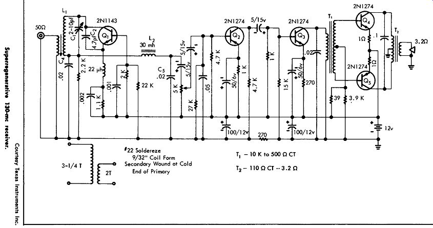
SUPERREGENERATIVE 130- Mhz RECEIVER
This circuit shows a super regenerative receiver designed for 130 megacycle operation. A receiver of this type has a very high sensitivity and represents a rather simple circuit as compared with a super heterodyne or a tuned radio-frequency receiver.
In this circuit, transistor Q1 operates as a self-quenched oscillator, with the audio appearing across the collector load resistor. The following stage is a 2N1274 audio amplifier, or predriver. The output of this stage is coupled by means of an RC network to the 2N1274 audio driver, which, in turn, is transformer-coupled to the pair of 2N1274 audio-output transistors operating in push-pull. A low-pass filter made up of L2, C4 and C5 eliminates the quench frequency from the audio output.
This receiver is designed to cover the range from 110 to 140 mhz; it is possible to change inductance L1 as well as tuning capacitor C1 and feedback capacitor C2 to modify this receiver for other frequency bands. The circuit shown has a sensitivity of about 4 micro volts, and a bandwidth of 4 megacycles.
------------
--------------
27- Mhz REMOTE-CONTROL TRANSMITTER
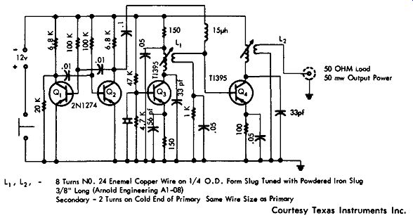
This circuit shows a 27-megacycle remote-control transmitter using four transistors. Transistors Q1 and Q2, which are both type 2N1274, are used as a free-running multivibrator that operates at 1 khz. The square-wave output from this multivibrator is applied to the base of transistor Q4. The modulation turns Q4 alternately off and on.
The TI395 crystal oscillator (Q3) feeds Q4, which is the output stage; the d-c input to the final stage is 100 milliwatts, while the power output is 40 mw. This unit is used as a remote-control transmitter; closing the switch connected in the positive lead of the 12-volt supply causes a 27-megacycle output modulated at 1 kilocycle.
50 OHM load 50 mw Output Power 8 Turns NO. 24 Enamel Copper Wire on 1/4 0.0. Form Slug Tuned with Powdered Iron Slug 3/8" Long () Secondary - 2 Turns on Cold End of Primary Some Wire Size os Primary
------------ Courtesy Texas Instruments Inc.
27 -mhz remote-control transmitter.
---------------
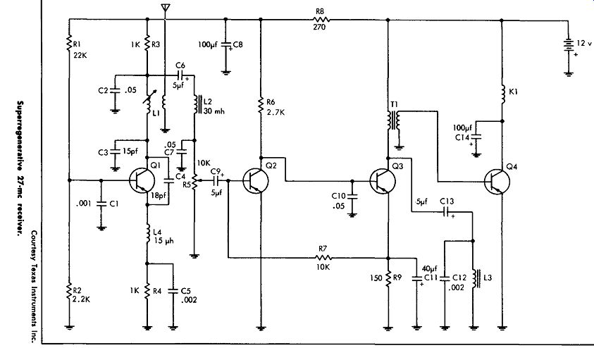
SUPERREGENERATIVE 27-Mhz RECEIVER
This circuit shows a super-regenerative receiver designed for the 27-megacycle Citizens band for use as a remote-control receiver.
Transistor Qt, a 2N2188, operates as a self-quenched oscillator pro viding an audio voltage across resistors R5, which is coupled to the base of transistor Q2, a 2N1274. 02 is the predriver audio stage.
Inductor L3 and capacitor C12 provide a tuning circuit that is resonant at 1000 cycles. Modulating a 27-megacycle carrier signal by 1000 cycles allows for remote control; when this signal is received, transistor Q4 will conduct and operate relay K1 in the collector circuit.
The relay itself can be used to actuate the necessary control equipment.
L1-Adjustable r-f coil (J. W. Miller #4403 or equivalent). Add 2 turns of #24 enameled wire on cold end.
L 2-30 Mhz choke (Bud CH 1228 or equiv.) L 3-8.5 hy (Stancor C1 279 or equiv.) L4-RFC, 15 µh (Delevan 1537-40 or equiv.)
Q1-2N2188 Q2-2Nl274 Q3-2N1274 Q4-2Nl274 K1-Sigma #11 F-2300-G/Sil T1-I0K to 2K