Diffraction--The True Story
by Robert C. Kral
Diffraction is an acoustic phenomenon that has taken its place beside the Loch Ness monster as a creature suffering from an identity crisis. The major difference between the two is that diffraction has received relatively little attention. In the following article I thoroughly document dif fraction's effect on loudspeaker systems, in an attempt to clear once and for all the murky depths of the loch.
WHAT IS DIFFRACTION?
Suppose you are standing on a bridge supported by rectangular concrete pillars sunken into the bed of a small river. It's a quiet afternoon; you're relaxing. You pick up a pebble and drop it into the water below.
Now watch what happens. When the wave crest created by the pebble approaches the rectangular pillar, the pillar's front and sides create noticeable disturbances. This is similar to what happens when a sound wave traveling through air strikes a solid rectangular object. The incident wave will tend to pass around the obstacle, and in the process its direction of propagation will change. This phenomenon is known as diffraction.
In 1938 Muller, Black and Dunn gave diffraction a rigorous mathematical treatment 1. They investigated the diffraction produced by differently shaped objects in the laboratory, then tried to approximate the experimental results mathematically with the theory they developed. Fig. 1 shows their results for a cube. The vertical scale shows the difference between the sound pressure on the front face of the cube and the constant sound pressure of the incident wave, express ed in decibels, while the horizontal scale gives the ratio of the length of the front face of the cube to the wavelength of the impinging wave.
Take a look at Fig. 1's 0 = 0, 9 = 30, and 9 = 60 degree curves. Notice how the sound pressure increases and then becomes constant as the wavelength becomes small in comparison to the size of the cube. This characteristic has some interesting historic value.
In the 1920s experimenters began to suspect an inaccuracy in their sound pressure measurements. They reasoned that the pressure at their microphone's diaphragm would be double that in the undisturbed sound wave because the wave would be reflected by the diaphragm. To compensate for this effect, they halved all their sound pressure measurements.
Other experimenters were hesitant to follow suit. They reasoned that the measured sound wave would not be reflected by the diaphragm: instead, they suspected the wave would flow around the microphone. This controversy prompted investigation into diffraction which proved that if the wavelength is small compared to the size of the diaphragm, the wave will reflect. If the wavelength is large com pared to the size of the diaphragm, the wave will flow around it. Therefore, the effect of diffraction is to vary the sound pressure on the diaphragm from the true pressure in the incident wave, at low frequencies, to double this value at high frequencies. Fig. 1 nicely documents this effect.
Note two important points. First, diffraction is contingent upon frequency. In other words, the effects of dif fraction will vary depending on the relation of the obstacle's size to the wavelength of the incident wave.
Secondly, diffraction is contingent upon the angle at which the incident wave strikes the object (we call this the angle of incidence). Diffraction's effect is most pronounced when the incident wave strikes the object squarely (the angle of incidence is zero), and is mitigated as the angle of incidence in creases.
THE ODD COUPLE: DIFFRACTION AND THE SPEAKER CABINET
Our discussion so far must seem devoid of any relation to loudspeaker systems and their performance. Enter the acoustic reciprocity theorem! Muller, Black and Dunn found the diffraction caused by a cube in a sound field. They measured the sound pressure with a microphone placed in the cube's front face, creating the sound field by placing a loudspeaker
four feet away. The acoustic reciprocity theorem says, in short, that the same sound pressure will be recorded at the microphone regardless of whether the loudspeaker (the source) and the microphone (the point of measurement), exchange positions. In other words, Fig. 1 also shows the effect of diffraction on the frequency response of a loudspeaker mounted in a cube, as measured by a microphone four feet away.
We may now tailor the two points I brought out earlier to fit this new situation. First, diffraction varies with frequency-or, alternately, diffraction is contingent upon the wavelength the loudspeaker produces and the size of the speaker enclosure. Secondly, the effects of diffraction vary depending on the position of our microphone relative to the system's axis. The effects of diffraction are most severe right in front of the speaker (on axis), but diminish as one moves to one side or the other (off axis). Before we get carried away, I have to temper these remarks. A driver will not diffract sound waves over its enclosure's outside surface if it is "beaming.'' In other words, diffraction poses problems only at those frequencies that the driver radiates strongly 90 degrees off axis (parallel to the surface of the front baffle). And all diffraction experiments must be carried out in an anechoic chamber. In a normal reflective environment it would be impossible to isolate the effects of diffraction.
OLSON AND THE GOLDEN RULES
In 1951, Harry F. Olson determined the effect of diffraction on the frequency response of a small, full range driver mounted on the front baffle of each of 12 differently shaped enclosures2. His results for cubical, rectangular, and spherical enclosures appear as the solid curves in Figs. 2, 3, and 4.
Let's look at the cube first. The sharp discontinuities at each edge of the front surface produce a strongly diffracted wave. The first peak occurs at 460Hz and the other peaks and dips occur at multiples of this frequency. Not coincidentally, 460Hz corresponds to a wavelength of 2.4 feet, which is approximately the cube's width.
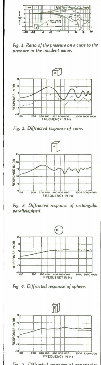
Fig. 1. Ratio of the pressure on a cube to the pressure in the incident wave.
Fig. 2. Diffracted response of cube.
Fig. 3. Diffracted response of rectangular parallelepiped.
Fig. 4. Diffracted response of sphere.
Fig. 5. Diffracted response of rectangular truncated pyramid & parallelepiped.
DIFFRACTION--THE TRUE STORY
Now let's look at the rectangular enclosure. Alas, problems arise. It's difficult to make the same generalizations we made about the cube because the driver is not equidistant from all four edges. In the case of the cube, each edge produced diffracted waves of the same phase and amplitude, compounding the net effect. This brings us to the First Golden Rule of Thumb for loudspeaker engineers concerned about diffraction:
1. Loudspeakers mounted on the front baffle of an enclosure should not be equidistant from any two or more sides. This will help ensure that the effects of diffraction will be staggered.
Fig. 4 is really interesting. Notice the sphere causes no significant peaks or dips whatsoever, because it has no sharp edges; the diffracted waves are therefore of uniformly varied phase and amplitude. Since a spherical enclosure would be difficult to con struct Olson proposed a rectangular truncated pyramid and parallelepiped combination. Fig. 5 shows the enclosure and its frequency response characteristic. This brings us to the Second Golden Rule of Thumb for diffraction-conscious engineers:
2. There should be no sharp boundaries on the front baffle of an enclosure upon which drivers are mounted. In other words, there should be a smooth, gradual transition from the cabinet's front to its sides. (Sorry, rounding the edges with a file won't help.)
THE WORLD RIDDLE
Trouble is, diffraction's a cloudy issue, similar in this respect to Doppler distortion and phase coherence. One must wonder why manufacturers are bent on building rectangular enclosures if these boxes are plagued by diffraction.
Are our views biased? Olson, by mounting one full range driver at or near the center of each enclosure and measuring the effects of diffraction directly on-axis, surely evaluated a worst-case condition. Most high fidelity speaker systems consist of two or more drivers, each producing its own peculiar pattern of diffracted waves depending on the bandwidth it covers,, where it is mounted, its radiation 90 degrees off-axis, and the crossover network. And people often listen to a stereo set-up way off-axis.
So what's happening in the real world?
THE ANSWER
Several years ago I endeavored to satisfy my curiosity by determining how diffraction affected the frequency response of a best-selling two-way bookshelf system. 31 began by writing a computer program based on Muller, Black and Dunn, which could predict the diffraction-affected response of a non-directional driver mounted in any given location on a rectangular baffle of any given dimensions. To check the program's utility, I tried to duplicate Olson's findings for a driver mounted in the center of a two foot cube. My results- the dotted curve in Fig. 2, displaced 5dB for clarity-compared favorably with Olson's. Then I applied the program to the bookshelf system under investigation.
Fig. 6 shows how diffraction would affect a full range non-directional driver placed in the tweeter's position on the enclosure's front baffle (the curves are displaced 5dB for clarity). Please note the broad 8dB peak centered at 1kHz and the 5dB valley centered at about 2.5kHz in the on-axis response. As the angle off-axis in creases, the peak becomes broader, the valley becomes shallower. At 60 degrees off-axis, the net effect is a boost of about 6dB at the higher frequencies. The curves for the woofer's position (Fig. 7) are similar, except the peak is centered at about 800Hz and the valley at 1.5kHz.
To apply these computed diffraction curves to the bookshelf system's drivers, I determined their bandwidths and relative strength of radiation 90 degrees off axis in an anechoic chamber. Although the woofer responded beyond 1kHz, it did not do so 90 degrees off-axis. All that diffraction could be responsible for, therefore, would be a broad peak centered at 800Hz. The tweeter, however, contributed measurably above 900Hz, and its 90 degrees off axis response was strong up to about 4kHz: hence, the tweeter's response should be elevated somewhat between 1 and 6kHz, with a 5dB valley in between.
Now look at the anechoic frequency response curves in Fig. 8 (displaced 5dB for clarity). In the on-axis plot, diffraction predictably imparts a broad 8dB peak centered at 1kHz. The boost incurred by diffraction is mitigated above 4kHz, where the tweeter begins to beam. Centered at 2.5kHz is a caver nous 13dB pit, attributable largely to diffraction. Surprisingly the off-axis curves follow the computed predictions even more closely. Notice how the curves flatten out at the off-axis positions, and how the 2.5kHz pit shrinks and moves up in frequency.
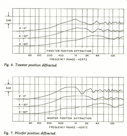
Fig. 6. Tweeter position diffracted.
Fig. 7. Woofer position diffracted.
A MORE DETAILED INQUIRY
We can best understand the unpredictably large valley at 2.5kHz by dissecting the on axis anechoic curve (Fig. 9). The solid line shows the woofer's response in the system, the dashed line shows the tweeter's response, and the dotted line shows how the two combine in the crossover region. Notice the tweeter is solely responsible for the dip, which centers at 2kHz rather than 2.5kHz, where the computed curves suggested it should be. The enclosure sides are solely responsible for this.
When 1 mounted the tweeters in a mock-up of the front baffle itself, so no enclosure sides affected diffraction, the dip moved back to 2.5kHz (its amplitude was unaffected). Part of the problem is a crossover anomaly. The tweeter and woofer responses add at 1kHz to raise the left wall of the dip 5dB. And in Fig. 10, note the right wall of the dip is raised 5dB by a 4kHz peak in the tweeter's on axis response, measured outside the cabinet with the crossover connected.
This peak is apparently caused by dif fraction around a 4" square piece of W" pressboard, upon which the tweeter diaphragm is mounted, and which is mounted by design a quarter inch in front of the front baffle.
Because this diffracting surface is a part of the tweeter, and because there is free space between it and the front baffle, the pressboard will color the tweeter's response regardless of whether we evaluate the tweeter in the cabinet or in free air. At any rate, these two problems contribute five decibels to the 13dB aberration.
Finally, diffraction around an inch deep rectangular molding, which serves as a grille frame on the cabinet front, adds 3dB to the 1kHz peak, 3dB to the 4kHz peak, and 1-dB to the 2.5kHz dip, for a net effect of four decibels. I evaluated the effects by removing the molding from the front baffle mock-up mentioned earlier (rather than by sawing the molding off the original enclosure) by mounting the tweeter in its proper location, and by measuring its response on-axis. The molding had a similar though somewhat more subtle effect on the off-axis response. Nevertheless, this accounts for four more decibels of the 13dB aberration, leaving an approximate 4dB dip at 2.5kHz, neatly attributable to diffraction around the edges of the enclosure.
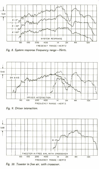
Fig. 8. System response Frequency range-Hertz.
Fig. 9. Driver interaction.
Fig. 10. Tweeter in free air, with crossover.
WHAT DOES IT ALL MEAN?
In home hi-fi speaker systems diffraction works in mysterious ways.
Although the front baffle edges are the main diffracting surfaces, other less obvious factors may cause the effects of diffraction to snowball. For instance, the edges may be responsible for 5 or 10 dB aberrations. If a driver is not mounted flush with the front baffle, diffraction might add or subtract up to 5dB to or from the system's frequency response. If a molding extends beyond the front baffle surface to serve as a grille frame, another 5dB may be add ed or subtracted. And if we do not give meticulous care to diffraction's role in the crossover region we might incur still other anomalies, perhaps 5dB or so in magnitude.
The end result could be a giant 25dB response variation; or diffraction might impart only a gentle five decibel boost at certain frequencies. That depends on how many drivers we use in the system, their bandwidths as limited by the crossover network, their radiation 90 degrees off-axis, and the size and shape of the enclosure. If these qualifications seem overwhelming, all we need to quell diffraction is to flush mount each driver on the front baffle so it is not equidistant from any two edges, and to eliminate all protrusions and abrupt discontinuities from the cabinet's front. If we take these two steps we need worry no further.
THE REAL WORLD
Right now you're probably saying, "Big deal. All these measurements have been made in an anechoic chamber. So what's diffraction doing in my living room?" Aha! Good question. Basically, you can forget about diffraction in your living room. I'll give you a few good reasons.
First of all, measuring a loudspeaker's frequency response on axis in an anechoic chamber gives no indication of how the speaker will per form in a room. Frequency response measurements taken in a reverberation chamber give a more accurate indication of its performance. Such a room reflects all the sound produced inside it--unlike an anechoic room, which absorbs all the sound. Hence, instead of measuring a system's response at one isolated, position relative to it's axis, the reverberation chamber averages out the system's response in all directions.
Now, since diffraction will occur only at those frequencies at which a driver is omnidirectional, and since its effects will be apparent only in a narrow area in front of the speaker, the diffracted waves represent only a small portion of the total sound produced by the speaker, even if they seem substantial in on-axis anechoic measurements.
Hence, the effects of diffraction will not be apparent in a reverberation chamber, nor will they be apparent in a normally reflective listening environment--especially when one considers that most serious stereo listening is done well off-axis, where the effects of diffraction have all but disappeared.
Also, sound waves inside a room are reflected and diffracted over and over again. Although the enclosure's front baffle may have been the main diffracting surface in the anechoic chamber, its role in a reflective listening environment could be radically different. In fact, more deleterious diffraction might occur around the bookshelf than around the bookshelf speakers.
SORTING IT OUT
You can see why manufacturers have metaphorically thumbed their corporate noses at diffraction: they feel rectifying the problem would not be "cost effective." Perhaps they are right.
A viable solution would necessitate construction of Olson's "rectangular truncated pyramid and parallelepiped combination." This enclosure is more difficult and therefore more expensive to fabricate than a standard rectangular box, yet it can yield no readily audible improvement. Most people don't know what diffraction is anyway, and they don't care. Perhaps this is as it should be. We may regard diffraction as kin to magnet weight and gap flux density: of consequence only insofar as it affects a readily measurable performance parameter.
Even then it's the black sheep of the family, since its effects vary with the loudspeaker's environment.
On the other hand, such a generalized philosophy may spawn other problems because of its inherent inflexibility. Imagine an engineer who does not recognize diffraction's existence, and who adjusts crossover networks in an anechoic chamber. He will incorrectly attribute the effects of diffraction to the drivers themselves. If he compounds the problem by adjusting the crossovers for maximum smoothness on-axis in the anechoic chamber, the system's frequency response in an average listening room will be anything but smooth.
And what about the poor soul whose speakers are adversely affected by dif fraction in his listening room? After all, such a situation is possible. The poor chap would have to listen to his speakers nearly on-axis, either out doors, where the environment is anechoic or in a room that absorbs most of the smooth off-axis response at the frequencies at which diffraction occurs. I can't think of a better example of this than a recording engineer in his studio. Yet I can't recall seeing a studio monitor that hasn't a rectangular, acoustically impossible cabinet.
And what about the audiophile who's just spent hundreds of dollars on a pair of 12 cubic foot monsters? Cost effectiveness can no longer be used as a valid excuse for designing an enclosure that defies common acoustic sense.
TO THE HOBBYIST
If you like to roll your own, the easiest way to deal with diffraction is to talk softly and follow the two Golden Rules mentioned earlier. Just adjust the dimensions of Olson's enclosure* to yield the interior volume you desire.
*"A rectangular truncated pyramid is mounted upon a rectangular parallelepiped. The lengths of the edges of the rectangular parallelepiped are 1, 2, and 3 feet. The lengths of the edges of the truncated surface are 1 foot and 2*/2 feet. The height of the truncated pyramid is 6 in ches. One surface of the pyramid and one surface of the parallelepiped lie in the same plane." Of course, if you lack the facilities to make the cabinet, don't worry about it.
Diffraction neither promotes tooth decay nor causes cancer in laboratory rats nor imparts a boxy sound to boxy loudspeakers. And if anyone tries to sell you that, just tell him it ain't so.
REFERENCES
1. G. G. Muller. R. Black, and T. E. Dunn, The Diffraction Produced by Cylindrical and Cubical Obstacles and by Circular and Square Plates," Journal of the Acoustical Society of America, Vol. 10, No. 1 (July 1948), pp. 6-13.
2. Harry F. Olson, "Direct Radiator Loudspeaker Enclosures," Audio Engineering, November, 1951.
3. Robert C. Kral, "Effects of Diffraction on Loudspeaker System Performance," IEEE Utah Section Student Proceedings, Vol. 5. No. 1 (April 1977).
ADDITIONAL READING
L. J. Sivian and H. T. O'Neil, "On Sound Dif fraction Caused by Rigid Circular Plate, Square Plate, and Semi-Infinite Screen," f. Acous. Society of America, Vol. 3 (April 1932), pp. 483-510.
Stuart Ballantine, "Effect of Diffraction Around the Microphone in Sound Measurements," Physical Review, Vol. 32 (December 1928) sic, pp. 988-992.
G. W. Stewart, "The Acoustic Shadow of a Rigid Sphere With Certain Applications in Architectural Acoustics and Audition," Physical Review, Vol. 33, No. 6 (1911) sic.
Harry F. Olson, Acoustical Engineering. D. Van Nostrand Company, 1957, pp. 17-26.
Also see:
An Ambience Reproduction Speaker System
Craftsman's Corner-- James Y. Pann's gargantuan speaker system