AMAZON multi-meters discounts / AMAZON oscilloscope discounts
Like the resistor discussed in the previous section, the capacitor is found in nearly every electronic circuit. The term "condenser" was formerly used when referring to this unit, and will still be heard occasionally, but "capacitor" is now more universally accepted.
WHAT IS A CAPACITOR?
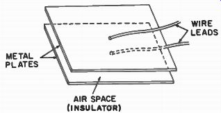
Fig. 1. A basic capacitor.
Basically, a capacitor is a device consisting of two plates of a conducting material separated by an insulator (Fig. 1) . This arrangement gives it the property of being able to store and release electrons as dictated by the external conditions affecting it. This storage and release is more commonly called charge and discharge.
CAPACITANCE
The property by which a capacitor is able to store electrons is called capacitance. The larger the plate area, the more electrons can be stored and hence the larger the capacitance. The unit of capacitance measurement is the farad.
Since this unit is too large for ordinary work, the micro farad (one millionth of a farad) is more common. Microfarad is abbreviated mf, mfd, id, or /dd. (The symbol it is the Greek letter mu, the abbreviation for one millionth.) A still smaller unit, the picofarad (abbreviated pf or pfd) is sometimes en countered. This unit is equal to one millionth of one millionth of a farad, or one millionth of a microfarad. In other words: 1 pf = .000001 mfd = .000000000001 farad.
The term micro-micro-farad (mmf, mmfd, µid, or iy,fd) was formerly used for picofarad and is still encountered quite often, but it is largely being replaced by the term "picofarad."
METAL FOIL PAPER SILVER CONDUCTORS CERAMIC
_ INSULATING CASE TERMINALS
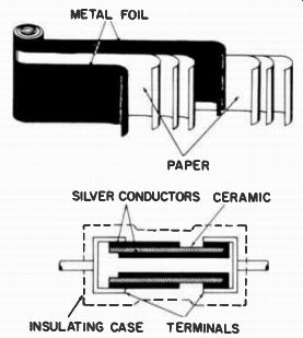
Fig. 2. Paper-capacitor construction.
Fig. 3. Ceramic-capacitor construction.
FIXED CAPACITORS
The capacitor shown in Fig. 1 is too large physically to be practical for most uses. If another insulating material is used instead of air, and if the plates are then rolled instead of lying flat, the unit can be made to occupy a much smaller space. This method is shown in Fig. 2. This assembly can then be enclosed in plastic or wax-impregnated paper.
Other types of fixed capacitors have the plates arranged in layers separated by thin sheets of mica or other suitable material. Here again, the assembly can be encased in plastic.
Fig. 3 shows the construction of a ceramic capacitor. The two metal plates (in this case, silver) are separated by a ceramic material and connected to the terminals at the end.
These terminals, in turn, are connected to the leads.
Color Codes
Most fixed capacitors either will have their value stamped on them or will have a color code to give this and other in formation. Several different codes are used, the most popular being given in Fig. 4. (The capacity is always given in picofarads.) In addition to the capacitance value, the working voltage is usually indicated also. This is the amount of voltage that can be continuously applied across the capacitor without its arcing and ruining the dielectric (insulating) material.
Symbols for fixed capacitors are shown in Fig. 5. The most popular is the one at A, having superseded B which was used for many years. Symbols C through G are for a special type of capacitor called a feedthrough. These units are either inserted through a hole in the chassis and soldered in place, or are screwed into a threaded hole. Typical feedthrough capacitors are pictured in Fig. 6.
Temperature Coefficient
Another rating often included in the color code is the temperature coefficient. Like resistors, capacitors often change in value when heated. To compensate for this, they can be manufactured so that their value will not vary at all, or will increase or decrease by predetermined amounts as the temperature changes. The temperature coefficient designates the amount of change in parts-per-million-per-degree centi grade. An N or a minus sign ( - ) indicates a decrease in capacitance, and a P or a plus sign (+), an increase.
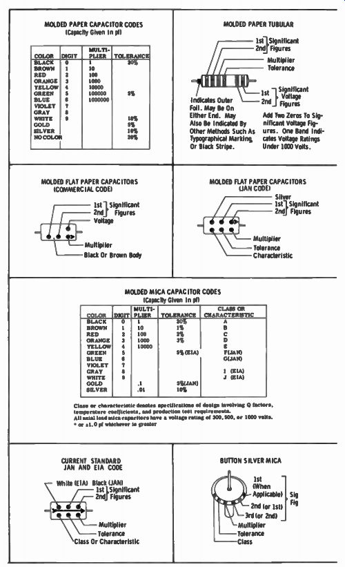
Fig. 4. Capacitor outline drawings and color codes. --- Class or characteristic
denotes specifications of design involving C) factors, temperature coefficients.
and production test requirements.
All axial lead mica capacitors have a voltage rating of 300.500, or 1000 volts • or )1.0 Id whichever is greater ---MOLDED MICA CAPACITOR CODES (Capacity Given In pi)
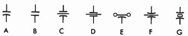
Fig. 5. Fixed-capacitor symbols.
ELECTROLYTIC CAPACITORS
Examples of another type of capacitor are shown in Fig. 7. These are called electrolytics because one plate consists of a moist substance called an electrolyte. Certain metals--aluminum is the most common--will have a thin oxide film form on their surface when immersed in an electrolyte. This oxide film becomes the insulation or dielectric between the metal plate and the electrolyte which serves as the other plate. Such capacitors are characterized by a high capacitance in comparison to their size.
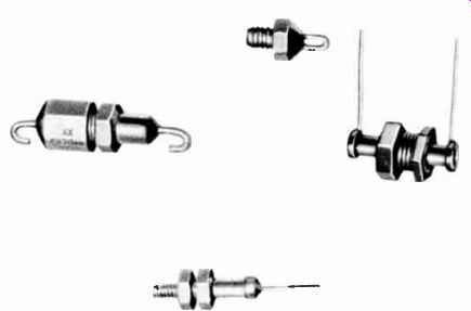
Fig. 6. Four types of feedthrough capacitors.
Unlike other capacitors, electrolytics must usually be connected in the correct polarity. That is, the positive terminal must go to the point with the most positive voltage, and the other side to the most negative potential, usually ground.
Fig. 8 shows the symbols for designating electrolytics on schematics. The same symbol used for regular capacitors is sometimes employed. However, a plus sign or plus and minus signs are usually added to indicate the proper polarity.
Symbol B is more popular, and here there is no doubt that it is an electrolytic. Other electrolytic-capacitor symbols are shown at C, D, and E.
More than one electrolytic capacitor is often enclosed in the same container. The negative side of all units will be connected together, but separate terminals or leads will be provided for the positive side of each. These multisection capacitors are sometimes designated by the symbols at B, C, and D-a separate symbol for each section. Occasionally the symbol at F, showing three sections, will be encountered.
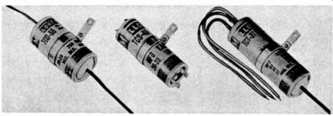
Fig. 7. Electrolytic capacitors. Courtesy P. R. Mallory & Co., Inc.
The symbol at G is preferred by some manufacturers for a two-section capacitor. Notice the small rectangle and tri angle near two sections in symbol F. Some units are enclosed in a metal can having twist prongs for mounting. The various sections are connected to terminals at the bottom, and small marks, such as a rectangle, triangle, or semicircle, are placed near them. These marks are stamped on the side of the can along with the respective value and voltage rating of each section, and are also included alongside the symbol in the schematic. These marks may also be included alongside any of the other symbols. Thus, they serve to identify the separate sections.
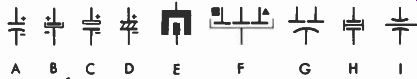
Fig. 8. Electrolytic-capacitor symbols.
Paper and other capacitors discussed previously will seldom have a value greater than 1 microfarad (it will usually be only a small fraction), whereas electrolytics will range from 1 to 200 microfarads or higher.
Because of their large values, electrolytics can store many more electrons. This makes them useful for smoothing out variations in voltage. They therefore find their widest application as filter capacitors in power supplies. Here, the voltage may vary over wide limits, but will always have the same polarity. Hence, the fact that electrolytics must-be connected correctly, polarity-wise, is not a hindrance.
In certain applications, however, a large capacitor is needed for a circuit in which the voltage does change polarity. Special non-polarized electrolytic units have been developed for this purpose. The symbols at H and I show the designation for such a capacitor.
VARIABLE CAPACITORS
Just as a variable resistor is useful in some circuits, vari able capacitors are also needed. The most familiar example is the tuning capacitor in many radios. As the tuning knob is rotated, the capacitor changes in value, causing its associated circuit to tune in the signal from the desired station.
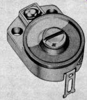
Fig. 9. A ceramic trimmer capacitor. Courtesy Centralab, Electronics Div.
of Globe-Union, Inc.
One type of variable capacitor is shown in Fig. 9. Its dielectric is ceramic and the capacitance is changed by turning a screw which moves one metal plate relative to the other.
This so-called "trimmer" is usually designated by symbols A or B in Fig. 10. The arrowhead in A signifies that the capacitance of the unit is variable. The symbol at B signifies a preset adjustment. That is, once set it is not normally adjusted except for alignment.
Another type of variable capacitor is illustrated in Fig. 11. Here, two sets of plates, each consisting of several flat pieces of metal connected together, mesh as the shaft is turned. Air is the dielectric, and if the shaft is rotated so the movable set of plates (called the rotor) is entirely surrounded by the stationary set (called the stator), the capacitance will be maximum. If rotated so the rotor extends out of the stator, it will be minimum.
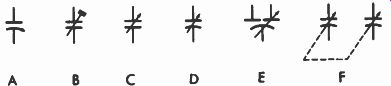
Fig. 10. Variable-capacitor symbols.
The symbols for a trimmer capacitor may also be used for the unit just described, although the symbols shown at C, D, E, and F in Fig. 10 are often employed. The arrow is used in various ways to designate a variable capacitance. For example, symbol E signifies a split rotor; that is, the stator plates are divided into two separate sections, but the rotor plates are not.
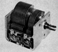
Fig. 11. A two-gang variable tuning capacitor.
The capacitor pictured in Fig. 11 is actually two separate units connected together mechanically by a single shaft. The larger unit tunes one section of a radio, and the smaller unit another section. Rotating the shaft changes the capacitance of each unit simultaneously. This type is called a ganged capacitor and is usually designated by the symbol at F in Fig. 10. The dashed line between the arrows signifies that both sections are mechanically connected.
CODE LETTERS
Nearly all fixed and variable capacitors are designated by the code letter C (one manufacturer uses E for electrolytics). The letters M, E, or VC are sometimes employed to signify variable units.
QUESTIONS
1. What is the primary purpose of a capacitor?
2. Do electrons flow through a capacitor connected to an AC voltage?
3. What is the basic unit for measuring the electrical size of a capacitor?
4. What is the insulating material between the two sides of a capacitor called?
5. Are electrolytic capacitors generally suitable for AC circuits?
6. What is the most common use for electrolytic capacitors?
7. What does the prefix "micro" mean?
8. What is the movable portion of a tuning capacitor called?
9. What is the most common code letter for capacitors?
10. Identify the types of capacitors signified by the following symbols.
(A)