AMAZON multi-meters discounts / AMAZON oscilloscope discounts
Just as any circuit or even a length of wire contains resistance and capacitance, it also will contain inductance-the electrical property of a coil.
WHAT IS A COIL?
A coil, or inductor as it is sometimes called, in its simplest form is just what its name implies-a wire wound into the shape of a coil. To be useful, however, coils must be wound in a certain way so that they will have the proper inductance value.
When current flows through a conductor, magnetic lines of force will be generated and will occupy the surrounding space. As long as the current is steady, the magnetic field will remain stationary, but if the current varies, the magnetic field will do likewise. Should the current stop suddenly (be shut off) , the lines of force will collapse.
Whenever magnetic lines of force cross a conductor, an electric current is generated. Thus, the magnetic field produced by the current flowing in one turn of a coil will cut across other turns, setting up a current in them. This is repeated for each turn in the coil. The over-all effect, when the current is made to increase, decrease, or change direction, is that the coil tends to oppose these changes. In other words, it tries to "smooth out" variations in current. A steady current (DC) will have no opposition except for the small resistance of the wire itself.
The electrical property of a coil is called inductance. The basic unit of measurement is the henry (abbreviated h), but like the farad, smaller units are often needed. The millihenry (mh), equal to one-thousandth of a henry, and the micro henry (ah), equal to one-millionth of a henry, are the more common units for specifying inductance values.
AIR-CORE COILS
The simplest coil has an air-core and is constructed by winding a wire into a series of loops. The more usual method, however, is to wind the wire onto a plastic, paper, or other nonmetallic form. As long as this form is not capable of being magnetized (not a conductor of magnetic lines of force), the effect is the same as if no form were employed.
The two air-core coils shown in Fig. 1 are wound on a phenolic form. The symbols used for air-core coils are given in Fig. 2. The loops will usually be shown open as in A, although some manufacturers prefer the simpler symbol at B.
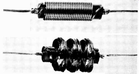
Fig. 1. Two types of air-core coils. Courtesy of Merit Coil and Transformer
Corp.
Air-core coils may or may not be color coded. In any case, the value is usually given either next to the symbol on the schematic or in the parts list, and will always be in the milli-henry or microhenry range-never in henrys.
The code letter L is practically universal for coils of all types. The letters RFC (meaning Radio-Frequency Choke) or the letter X may sometimes be used.
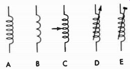
Fig. 2. Air-core coil symbols.
Adjustable Air-Core Coils
It is often desirable to change the inductance of a coil. This can be done by making the coil adjustable. Symbols for this type are shown at C, D, and E. It can also be represented by adding the adjustable symbol to the symbol at B. The symbol at C is often used to depict a coil having a slider that moves along the turns to "switch in" the desired portion. D may be used to indicate a coil in which the inductance is changed by either compressing or expanding the turns to change the spacing between them. Both symbols are interchangeable, however.
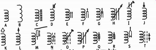
Fig. 3. Powdered-iron core coil symbols.
POWDERED-IRON CORE COILS
Other types of coils have cores of ferrite or powdered iron (called iron-dust in some parts of the world). Ferrites are made by molding powdered iron or a similar substance into the desired shape. When such a core is brought near or inserted into a coil, it offers a more convenient path for the magnetic lines of force than does air. Hence, more lines cut the other conductors in the coil, increasing the inductance.
The same symbols used for the air-core type-A and B in Fig. 3-may also be used for powdered-iron core coils. The symbol at C is also popular. The core may be represented by either two or three dashed lines.
Adjustable Cores
To change the inductance of powdered-iron core coils, the core is usually moved in or out of the unit. This is called permeability tuning; three examples of coils tuned in this manner are shown in Fig. 4. Many types of symbols are used to indicate the adjustable core. Some are shown at D through T in Fig. 3. Notice that most follow the same pattern of showing an arrow, but in a different manner.
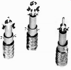
Fig. 4. Permeability-tuned coils. Courtesy Triad Distributor Division, Litton
Industries
Most permeability-tuned coils are in the millihenry range, but the value is seldom marked on the units. Nearly all manufacturers designate this type of coil by the letter L.
IRON-CORE CHOKES
Another type of coil has a core of iron or steel and is usually referred to as a choke, since its function is to smooth out ("choke") variations in the current through it.
The construction of a typical iron-core choke is illustrated in Fig. 5. Instead of the core being a solid piece of metal, it is usually constructed from a series of thin sheets, or laminations (visible at the center of the figure). Insulated wire is wound in layers around the core, each layer being separated by additional insulation (usually paper). These layers may be left exposed, or the entire unit may be enclosed in a steel shell. Coils of this type are able to provide a large amount of inductance, usually in the henry range.
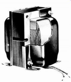
Fig. 5. Cutaway view of an iron-core transformer. Courtesy Merit Coil and
Transformer Corp.
The symbols for iron-core chokes are given at A, B, C, D, and E in Fig. 6. Note that they are the same as for other types of coils except that two or three solid lines are added to indicate the iron core. (The closed-loop symbol at D can be used for any of the core designations shown with open loops.) The symbols at F and G are for tapped units-that is, connections to different points on the winding permit particular portions or sections of the coil to be used.
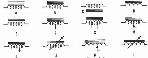
Fig. 6. Iron-core coil symbols.
Adjustable iron-core chokes are comparatively rare.
Usually, instead of being continuously variable, a series of taps and a switch are employed to make connection to the desired portion. When a continuously variable iron-core unit is used, however, it may be indicated by any one of the symbols at H, I, J, K, or L. These are the same as for a conventional choke, but with an arrow added to signify the inductance can be varied.
The letter L is usually used to indicate an iron-core choke, although occasionally FC (filter choke) is used.
TRANSFORMERS
A transformer is merely two or more coils positioned in such a manner that the magnetic field produced as a result of current flowing through one winding will cut across the other winding or windings. When this happens, a current will be induced in these other windings, even though they are not physically connected to the first.
The winding connected to the voltage source is called the primary. Any other winding is called a secondary. Besides causing a current flow in the secondary, the transformer can also change the amount of voltage. If the number of turns on both the primary and secondary are equal, then the voltage across each will be the same. With more turns on the secondary than on the primary, the secondary voltage will be higher. Conversely, if the secondary has fewer turns, its voltage will be lower.
Thus, the main function of a transformer is either to transfer an AC voltage from the primary to the secondary, or to step the voltage up or down. In either case the current in the secondary will vary exactly in step with the current in the primary. This phenomenon is used in coupling, or transferring, energy from one stage to another. Adding a capacitor across the winding will produce a combination that will accept a particular frequency and exclude all others. Current will flow in the secondary (which may also be tuned by a capacitor) at this particular frequency only.
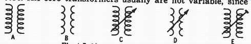
Fig. 7. Air-core transformer symbols.
Types of Transformers
Like coils, transformers may also have either air or iron cores. Fig. 7 shows the symbols for those having an air core. Air-core transformers usually are not variable, since the only way this can be done is to move one of the coils with respect to the other. If this is done, however, symbols shown by C, D, and E are used.
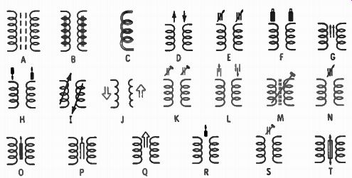
Fig. 8. Powdered-iron core transformer symbols.
Fig. 8 shows the symbols for designating a powdered iron core transformer. In this type the individual coils are usually wound on a single form (Fig. 9). In Fig. 9A the unit is shielded by a metal cover (called a can); the one in Fig. 9B has no such covering. Both units have capacitors connected across their windings for tuning.
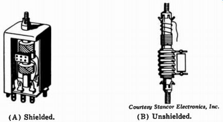
Fig. 9. Two types of permeability-tuned transformers. ( A) Shielded. ( B)
Unshielded. Courtesy Stances Electronics, Inc.
A special winding, called a bifilar, is sometimes indicated by the symbol at C in Fig. 8. In this type of unit the conductors for both windings are placed side by side and wound on the form together.
The symbols at D through L in Fig. 8 usually are employed to indicate that each winding is separately tunable, while the symbols at M through T indicate the tuning adjustment affects both windings simultaneously.
Iron-Core Transformers
There are many types of iron-core transformers. Fig. 10 shows two popular methods of construction. The unit in Fig. 10A is an audio-output transformer, while Fig. 10B illustrates a power transformer for a television receiver. In the latter unit all the windings are enclosed in a metal case with their leads brought out through two openings in the bottom.
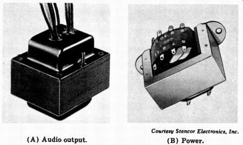
Fig. 10. Two types of iron-core transformers. (A) Audio output. (B) Power.
Courtesy Stancor Electronics, Inc.
Iron-core transformer symbols are given in Fig. 11.
Two or three lines may be used in the symbols at A, B, and C to indicate the iron core. Parts A, B, C, D, and E show five ways of indicating a unit having only two windings, while part F represents a transformer having four. Here, the primary is the winding on the left, and the top winding on the right is a low-voltage secondary (as signified by the fewer turns) for the filaments of the rectifier tube. The center winding is the high-voltage portion and is center tapped. The winding at the bottom is for the filaments of all other tubes in the receiver.
A special type of transformer, called an autotransformer, is symbolized at G. The portion from one end to the tap acts as one winding, and the complete coil, from one end to the other, acts as the other winding. Such units can step the voltage either up or down, and may have taps from which different voltages can be obtained.
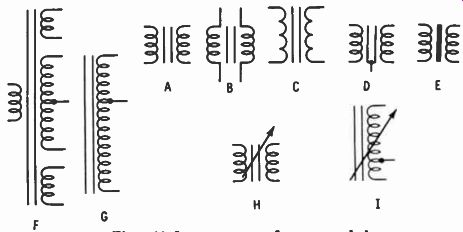
Fig. 11. Iron-core transformer symbols.
The symbols at H and I indicate variable iron-core transformers. Like the iron-core chokes, these types are seldom encountered. Tapped windings are usually employed instead.
The code letter T is almost universal for the designation of iron-core transformers. The letter L will sometimes be used, however, to indicate air- and powdered-iron-core trans formers and AOT may be used to signify an audio-output transformer.
QUESTIONS
1. What is the electrical property of a coil called?
2. What is the unit of measurement of the property in Question 1?
3. What effect does a coil have on steady DC flowing through it?
4. What enables one winding of a transformer to couple a current in another winding?
5. What is used to signify an iron core on a coil or trans former ?
6. What is the more common name for an iron-core coil?
7. What is the name of the transformer winding in which the incoming current flows?
8. What do two or three rows of dashed lines between the windings of a transformer indicate?
9. What code letters are used to designate transformers?
10. Draw the symbol for an air-core coil.