AMAZON multi-meters discounts AMAZON oscilloscope discounts
The entire foundation of electronics is based on the tiny, negatively-charged particle called an electron. These electrons will flow from a negative to a positive voltage source if a complete conductive path is provided. This flow constitutes an electron current. Unless it can be controlled in some way, however, it will serve no useful purpose. Electron tubes are one type of device used to control this flow.
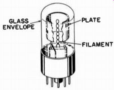
Fig. 1. Construction of a diode tube. GLASS ENVELOPE; PLATE; FILAMENT DIODE
TUBES.
Fig. 1 shows the elementary construction of the simplest of electron tubes-the diode. A length of special resistance wire, placed in the center of the unit, becomes hot when current flows through it. This heat causes electrons to be expelled from the surface of the wire (called the filament) into the surrounding vacuum. (The entire tube is evacuated of air, because the presence of oxygen would cause the filament to burn up.) Separated from the filament by the vacuum is another element, the plate (sometimes called the anode). If this plate is connected to a positive voltage source, the electrons "boiled off" the filament will flow toward it. If the voltage on this element is less positive than the filament, however, it will not attract electrons and no current will flow.
An alternating voltage (AC) placed on the plate will cause electrons to flow only during the time this element is more positive than the filament-not while it is more negative.
Hence, we have the first control action of a tube-changing an AC voltage (on the plate) into a pulsating DC (on the filament). This action is called rectification. The pulsating DC is then smoothed out by an electrolytic capacitor.
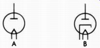
Fig. 2. Diode tube symbols.
The symbol for this type of tube is given at A in Fig. 2.
The circle represents the glass or metal envelope, the pointed portion at the bottom of the circle is the filament, and the straight horizontal bar with the vertical line extending up ward is the plate.
Another type of diode tube is indicated by symbol B. Here, an additional element called the cathode is placed between the filament and plate. This element is a metal sleeve, coated with a special electron-emitting material. It fits over the filament, which now is used only to furnish heat. The advantage of this arrangement is that the heated cathode can produce more electrons than the filament and, in addition, its emission does not change with the alternating current often used to heat it. In this type of tube the filament is more properly called the heater.
TUBE BASES
Connections are made from the elements of the tube to pins in its base. The most popular bases for modern tubes are the 7- and 9-pin miniature and the 8-pin octal. In the 7- and 9-pin types, the pins are merely symmetrically-spaced wires which extend through the bottom of the glass envelope. A blank space between two of the pins serves as a guide for inserting the tube into the socket. In an octal-base tube, wires from the tube elements pass through the glass envelope and are soldered to pins embedded in a plastic or phenolic base.
A keyed center post on the base serves to guide the tube into its socket.
There are many other base arrangements. Most will have a blank space, locating key, or other provision for orienting the tube in the socket. In some tubes, all pins are not connected to elements. In fact, some pins may even be omitted from the base if a locating key is employed.
Each pin is numbered for reference purposes. With the base pointed toward you, pin 1 is the first pin starting clock wise from the blank space or locating key. All other pins are numbered consecutively, reading clockwise around the base.
(If a pin is omitted, the number ordinarily assigned to it is skipped, but the location of the other pins remains the same.) These pin numbers are also placed on schematics next to the tube symbol, at the point where the respective tube elements enter the tube envelope. When this type of symbol is used, it is known as a basing diagram. By referring to the numbers beside the elements, you can locate the pin connected to each element.

Fig. 3. A diode tube with a plate cap.
In some tubes the connection to an element will be brought out the top to a cap instead of to a pin on the base. The cap is almost always connected to the plate. (In pre-World War II tubes it was often connected to another element called the grid.) A cap is usually symbolized by a small box around the lead, at the point where it enters the tube envelope. This is shown in Fig. 3, along with the pin numbers of the filaments.
TRIODE TUBES
The diode tube discussed previously performed only one control action-it converted an AC current to a pulsating DC current. The widest function of tubes, however, is to amplify a signal (i.e., make it greater). The diode tube can not do this; in fact, it actually causes a slight reduction in A signal strength. For amplification, at least one more element must be added between the cathode and plate, as shown by the drawing of a triode, or 3-element tube in Fig. 4. The added element, a cylinder made of fine-wire mesh, is called the control grid. This grid is represented by the dashed line between the cathode and plate in symbol A of Fig. 5.
GLASS ENVELOPE CATHODE PLATE GRID
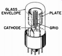
Fig. 4. Construction of a triode tube.
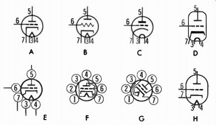
Fig. 5. Triode tube symbols.
In this type of tube, electrons will flow from cathode to plate, but they must first pass through the intervening control grid. Like the plate, the control grid is able to regulate the electron flow from the cathode-the more positive the control grid, the greater the electron flow, and vice versa.
Being closer to the cathode, it exerts more influence than the plate, however.
TUBE VOLTAGES
The cathode-or in filament-type tubes, the minus side of the filament-is the reference point of all voltages in the tube since it emits the electrons. The cathode is connected either directly, or through a resistor, to this common reference point, generally referred to as simply ground. Hence the cathode voltage is either zero, or at most, slightly positive.
The grid is usually a few volts negative with respect to the cathode. Recall that a negative voltage will repel the electrons as they attempt to flow through the tube. However, electrons will still flow through the openings in the grid structure unless the voltage applied to it is too negative.
Then, the grid repels all the electrons back to the cathode and the tube is said to be cut off. As the grid becomes less negative, however, more electrons will be drawn through it by the positive potential on the plate. If the grid becomes positive with respect to the cathode, it will also attract the electrons, and they will flow in the grid circuit.
As you can see, the electron flow of the plate will alternately increase and decrease if a varying voltage, such as an AC signal, is applied to the grid. These increases and de creases in the amount of electron flow through the plate resistor will cause much larger voltage variations at the plate than those of the grid signal which caused them.
SYMBOLS
The symbols used by most manufacturers to denote tubes are all very similar. Formerly, the symbol at B in Fig. 5 was used in which the zigzag line denoted the grid. It is seldom encountered today, however. The circle denoting the envelope is sometimes omitted, especially in pencil sketches.
Another way of showing the cathode and heater is given at C. Here, the cathode and filament are both curved. Also notice that the shape of the plate has been changed slightly.
Another method of denoting the cathode is given at D. Probably the major discrepancy in tube symbols is in the method of showing the pin or base connections. One method was shown in Fig. 3 and again in A and B of Fig. 5. Other ways of designating the bases are given at E, F, and G. These symbols show circles spaced around the tube envelope with the pin numbers inside. These numbers are arranged in the same order and in the same position as they actually appear on the base at F and G, with the various elements inside the envelope shown connected to their respective pins. The elements within the tube are sometimes tilted as in G. Any of the symbols in Fig. 5 may be lying on their side, or even upside down. The envelope may be elongated, as shown at D and H, instead of being shown as a circle. In each case, however, the basic symbol remains the same. These variations will not always be mentioned in the following sections of this section, but remember that they may exist.
TETRODE TUBES
In Section 3 it was stated that a capacitive effect would exist between two conductors separated by an insulator. In the previously discussed triode tube, a certain amount of capacitance exists between the grid and plate. This inter electrode capacitance, as it is called, is detrimental to circuit operation in certain applications. To reduce its value, a fourth element, called a screen grid, can be placed between the grid and plate. Such a tube is called a tetrode, and its symbol is shown in Fig. 6. Notice the additional element, which looks exactly like the control grid in the drawing. In fact, its physical construction is very similar, but unlike the control grid, it is connected to a high positive voltage. A by pass capacitor, usually connected from the screen grid to common ground, makes this element appear at neutral (ground) to any signal voltage in the tube. As a result, the shielding action of the screen greatly reduces the effect of the capacitance between the control grid and plate. In addition, tetrode tubes are characterized by a much higher gain (provide more amplification) than can be obtained from a triode.

Fig. 6. Symbol for a tetrode tube.
PENTODE TUBES
The tetrode tube would seem to be ideal, since it overcomes the disadvantage of the interelectrode capacitance found in a triode, and at the same time gives more amplification. But its effectiveness is limited by another phenomenon known as secondary emission. As the electrons from the cathode strike the plate, some of them bounce off and some of the electrons already on the surface of the plate are also knocked loose.
All these are attracted by the positive potential on the screen.
Thus, the screen grid receives more than its share of electrons while the plate, which is the intended destination of the electrons, receives less. As a result, more electrons flow in the screen circuit (known as screen current) and fewer in the plate circuit (plate current). The effect of secondary emission can be overcome by adding another element, similar in construction to the control and screen grids, between the screen and plate. This element is called the suppressor grid, and the type of tube in which it appears is called a pentode. The suppressor is connected to either the cathode or ground. Recall that a positive voltage is a point where there is a deficiency of electrons, and that a negative voltage is a point where there is an excess. The suppressor grid, having far more electrons than the plate, repels the secondary-emission -- electrons back to the plate before they have an opportunity to reach the screen grid.

Fig. 7. Symbol for a pentode tube.
The symbol for the pentode tube is shown in Fig. 7.
Notice that it is the same as the symbol for the tetrode except for an additional grid between the plate and screen.
BEAM-POWER TUBES
The beam-power tube is often thought of as being a pentode, although its operation is more like that of the tetrode.

Fig. 8. Symbol
for a beam-power tube.
Fig. 8 shows its symbol. Instead of a suppressor grid, it has two metal vanes (called beam-forming plates) positioned in such a way as to guide or focus the electrons toward the plate (Fig. 9) . In addition, the wires of the screen and control grids are in line, permitting more electrons to flow through. In this way, the tube can deliver much greater power.
The beam-forming plates are connected to the cathode in side the tube. The regular tetrode (Fig. 6) or pentode (Fig. 7) symbol is sometimes used for the beam-power tube. In either instance, a tube manual will have to be consulted to determine whether or not the tube in question is a beam power type.
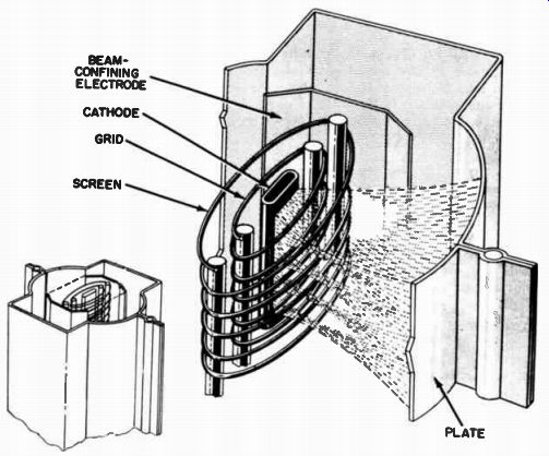
Fig. 9. Construction of beam-power tube. BEAM CONFINING ELECTRODE CATHODE
GRID SCREEN
PENTAGRID TUBES
Fig. 10 shows the symbol for a pentagrid tube. It has a total of five grids between the cathode and plate, and performs two functions in a radio. The first is that of the local oscillator, a stage which generates a high-frequency signal.

Fig. 10. Symbol for a pentagrid tube.
The first grid acts as the oscillator grid and the second as the plate. Electrons will flow on through it, however, toward the conventional plate of the tube. The third grid acts as the A control grid for the remainder of the tube. This portion is similar to a conventional pentode and has the signal from the antenna applied to its grid. The electron stream is already varying in accordance with the oscillator frequency when it reaches the third grid. The two signals (from the oscillator and antenna) beat together, or heterodyne, producing a new signal which varies in the same manner as the signal applied to the third grid, but has a frequency equal to the difference between the two signals. This action is called mixing. The fourth grid (connected to the second) functions as the screen for the pentode section, and the fifth functions as the suppressor.
DUAL-SECTION TUBES
Two or more tube functions are often combined in a single envelope. Some of the more popular combinations are: two diodes ; two triodes ; two diodes and a triode or pentode ; and a triode and pentode. The elements for both tubes are some times drawn side by side in the symbol, as shown at A in Fig. 11. The dashed line through the center represents a shield placed between the two sections to prevent interaction. Some tubes do not have this shield. If the two halves are in separate circuits they will usually be drawn as shown at B. Here, the dotted line at one side signifies that there is another section of the tube. Symbol C, with the dotted lines omitted and the side left open, will sometimes be used instead. You may occasion ally find schematics in which one half of a dual-section tube will be completely enclosed within the circle, exactly like the single-section tube shown previously. The parts list will usually indicate that the tube is a dual-section type, or if not, a tube manual can be consulted.
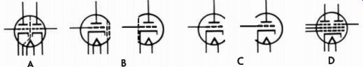
Fig. 11. Dual-section tube symbols.
Another type of dual tube is depicted by symbol D. Here the tube is actually a dual-pentode, except that the same cathode, control grid, and screen grid serve (are common to) both sections. In other tubes only the cathode may be shared. If so, and if each section is drawn at a different place on the schematic, the cathode will be shown in both places but the same pin number will be placed beside the cathode symbol.
In some dual-section tubes the filament is tapped in the center so that it can be operated from either 6 or 12 volts.
Two filament connections will be shown in one half of the tube and one in the other half, as depicted by symbol B of Fig. 11. An untapped filament will be shown by symbol C. Here, one side of the filament connection is given in each section. The filament is shown in each half, as in a single section tube, but only one line extends beyond the envelope.
GAS-FILLED TUBES
Instead of being evacuated, certain tubes are filled with a gas. Some tubes of this type require no filament voltage- hence are called cold-cathode or ionically-heated cathode tubes. Symbol A in Fig. 12 is for a cold-cathode diode tube.
Notice that instead of a flat bar, a circle is used to represent the cathode, and no filament is shown. Sometimes this circle is replaced by a dot, as at B. In either symbol, a smaller dot, indicating a gas-filled tube, also appears inside the envelope.
The other connection shown inside symbol B is a wire between two pins on the tube base. Its purpose is to open another circuit when the tube is removed. This protects the equipment if accidentally turned on with the tube out of the socket.
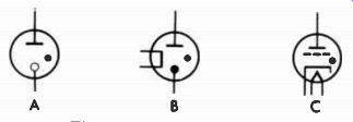
Fig. 12. Gas-tube symbols.
The symbol for another type of gas-filled tube, called a thyratron, is given at C. It is the same as the symbol for a triode except for the dot inside the envelope. The thyratron is used in certain control applications.
PHOTOTUBES
Symbol A in Fig. 13 depicts a different type of tube.
Certain materials-potassium, sodium, and cesium, for example-give off small quantities of electrons when exposed to light. A curved piece of metal with a coating of this photo sensitive material acts as the cathode. The plate (anode) is a metal rod in front of it. When light strikes the photosensitive material, electrons are released and flow to the plate. In the symbol, the curved portion represents the cathode, and the flat bar (or a dot or circle) represents the plate (usually called the anode in a phototube).
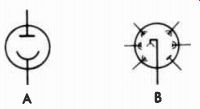
Fig. 13. Phototube symbols.
The symbol for another type of phototube, called a photo multiplier, is shown at B. The main cathode is the curved element at the center from which electrons flow to the first element at the bottom left of the symbol. This element, in turn, emits more electrons to the next similar element.
(Notice that the symbol for the elements around the outside of the tube are a combination of the photocathode and anode symbols.) These elements attract the electrons, and each in turn emits more electrons than the preceding one, until finally the element to the right of the cathode lead is reached. Here, the conventional anode symbol is used for the element from which the output is taken. Because of this multiplier action, many more electrons flow from the output than could flow from the tube at A.
ELECTRON-RAY TUBES
The electron-ray, or tuning-eye, tube is used on some radios and tuners to indicate when the set is tuned exactly on station, and with tape recorders to indicate the recording level.
The simplest tuning eye is essentially a triode with two electrodes added, as shown by symbol A in Fig. 14. The slanted element is called the target. Electrons emitted by the cathode strike this target and cause it to fluoresce (glow). The other element is the deflector, or ray-control electrode- a thin vertical vane placed between the cathode and target.
As shown by the symbol, the deflector is connected to the triode plate and causes a shadow to fall on the target. When the set is tuned exactly on the station frequency, the shortest shadow is cast. As the signal strength decreases, the shadow lengthens.
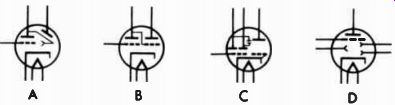
Fig. 14. Electron-ray tube symbols.
Some other symbols for depicting tuning-eye tubes are given at B, C, and D. All employ the same principle-that of a deflector casting a shadow on the target.
--------
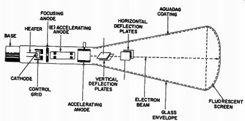
Fig. 15. Construction of an electrostatically-deflected cathode-ray tube.
BASE FOCUSING ANODE HEATER (E) ACCELERATING ANODE CATHODE CONTROL GRID HORIZONTAL DEFLECTION PLATES VERTICAL DEFLECTION PLATES ACCELERATING ANODE AQUADAG COATING ELECTRON BEAM GLASS ENVELOPE FLUORESCENT SCREEN
---------
CATHODE-RAY TUBES
Cathode-ray tubes are usually classified according to whether they employ electrostatic or electromagnetic deflection. The principal use for the former is in oscilloscopes, while the television picture tube is the most familiar application for the latter.
Electrostatic Deflection
Fig. 15 shows the construction of a typical electrostatic tube. The electrons leave the heated cathode, as in other tubes, and are attracted by the positive voltage on the accelerating anode. First, however, they must flow through the control grid, a metal cylinder with a hole in one end. A negative voltage on this element controls the number of electrons allowed to pass through. From the control grid, the electrons pass on to the focus anode, which concentrates them into a narrow beam that strikes the screen in a small, sharply defined area.
After the electrons leave the focusing anode, their velocity is increased by two high-voltage accelerating anodes.
The remaining electrodes are the deflection plates. The two horizontal plates move the beam from side to side across the screen, and the vertical-deflection plates move it up and down.
After passing through and being influenced by the deflection plates, the beam strikes the screen with great force, causing a fluorescent coating on the screen to glow. The brightness depends on the number of electrons and their velocity.
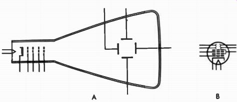
Fig. 16. Electrostatic cathode-ray tube symbols.
Symbol A in Fig. 16 is sometimes used to depict an electrostatic cathode-ray tube. (Note its similarity to the tube.) The elements are shown in the order in which they appear in the tube-from left to right they are the heater, cathode, control grid, focusing electrode, and accelerating anodes. The deflection plates are drawn in the form of a square.
At other times the symbol for the electrostatic cathode-ray tube resembles that of a conventional tube, as shown at B. Notice that here the focus electrode is placed between two sections of the accelerating anode. Where other arrangements are used, the schematic symbol shows the actual arrangement of the elements. The deflecting plates are represented by the four pointed electrodes at the top of the tube in symbol B.
Electromagnetically Deflected Cathode-Ray Tubes
The most familiar type of electromagnetically deflected cathode-ray tube is the one in your television tube, except it has no deflection plates. Instead, the beam is deflected both horizontally and vertically by coils around the neck of the tube. Often there are no focusing electrodes either; the electron beam is converged on the screen by a permanent magnet or an electromagnet around the neck.
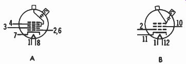
Fig. 17. Electromagnetic cathode-ray tube symbols.
Electromagnetically deflected tubes employ either an eight- or twelve-pin base. Fig. 17 shows two symbols for an electromagnetically deflected cathode-ray tube. Symbol A is for a tube employing electrostatic focus and having an eight-pin base. The elements are : the heater (pins 1 and 8) , cathode (pin 7), control grid (pins 2 and 6), first anode (pin 3), and focus electrode (pin 4) . The two grids connected to the square box on top of the envelope are the second anodes.
This box designates the so-called bulb contact, which fits through the side of the tube. The small capacitor, shown in side the tube and connected to the box labeled C, designates the capacitance between the coatings placed on both sides of the glass envelope. These coatings, called the aquadag, act as a capacitor to filter the high voltage connected to the bulb contact. Symbol B shows a twelve-pin electromagnetically focused tube; hence, no focus elements are included.
Another symbol for a cathode-ray tube is shown at A in Fig. 18. Here, the symbol resembles the actual construction of the tube. The elements, from top to bottom, are the heater, control grid, first anode, and second anode. A variation of symbol A is shown at B. Here, the symbol has been simplified by showing the tube neck broken at the bottom, and leaving the base pins off the top. This symbol is for an eight-pin, electrostatically focused tube. Still another method of symbolizing a cathode-ray tube is given at C.

Fig. 18. Other types of symbols used for electromagnetic cathode-ray tubes.
CODE LETTERS
Manufacturers are almost unanimous in selecting the letter V (for vacuum) to designate all types of tubes (vacuum or gas) on their schematics. One manufacturer, however, chooses to designate the socket, instead of the tube itself, by using the letter S. The letter T is also employed occasionally; but most save it for designating transformers, as discussed in a previous section.
QUESTIONS
1. What is the primary purpose of all electron tubes?
2. What is the purpose of the cathode in an electron tube?
3. What is the most common letter used to designate tubes on schematics?
4. What is a cold-cathode tube?
5. What is the most common type of cathode-ray tube?
6. From what element of the tube is the output normally taken?
7. How are connections made to the various elements inside the tube?
8. Draw the symbol for a triode tube.
9. Draw a thyratron tube.
10. Draw a dual-section tube ; one section a pentode, and the other a triode.