Tonearms can be classified into two categories: pivoted and tangential tracking, FIG. 7A and 7B.
Contemporary tonearms are designed to cope with a variety of problems. However, rarely can one find a tonearm with nearly perfect geometry and correct design to establish correct performance. Most tonearms have built in antiskating devices, adjustable counter weights to accommodate a variety of cartridge weights and tracking forces, vertical height adjustment to set the tonearm parallel to the record, and a variety of features to facilitate installation and operation of the device. All tonearms are at best a compromise. Very few tonearms are dynamically balanced, and most rely on dynamic unbalance to produce vertical tracking force. The dynamically balanced tonearm is the tonearm that is capable of playing a record with the turntable tipped at almost any angle without changing the tracking force and tracking ability.
Tonearm Geometry. Tonearms are designed to retrace the modulation of the groove in the same way as it was recorded. Design of the tonearm takes into consideration the diameter of the records or the turntable, and the distance between the center of the platter and the pivot point of the tonearm. Older tonearms suffered from a tangent error because the cartridge was aligned properly at only one point on the record. Today's pivoted tonearms have a built-in offset angle at which the cartridge is positioned so it is always perpendicular within a couple of degrees to the radius of the disc. This reduces distortion in the lateral plane and improve tracking. There are many protractors available today using different approaches to help position the cartridge as accurately as possible in the tonearm to minimize tracking error.
When a disc is being cut, the cutting head is carried across the face of the recording disc following the radius. However, when in playback, the pickup is at the right angle to the radius of the disc only at two points, because the pickup arm is pivoted in such a manner that it swings across the face of the disc in an arc, as shown in FIG. 8.
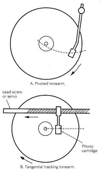
FIG. 7. Tonearm classification. A. Pivoted tonearm. B. Tangential tracking
tonearm.
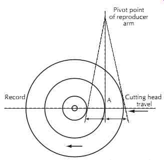
FIG. 8. Tangent error in a reproducing arm. The error is zero at point A only.
Pivot point of reproducer arm.
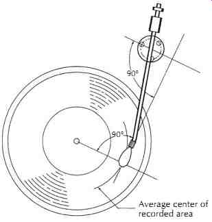
FIG. 9. Typical mounting for an offset pickup arm. Average center of recorded
area.
Generally, the manufacturer of the arm supplies a template and mounting instructions for a particular arm.
In the absence of such information, the pickup arm is mounted in such a manner that the tangent error is at a minimum. One method of mounting the arm is shown in FIG. 9. Regardless of where the pivoted arm is placed, a tangent error cannot be eliminated entirely.
The error can be made so small, however, that it can be neglected. In offsetting the tonearm by bending it into an S or J shape, FIG. 10, it is possible to position the cartridge so that at two points on the record the error shall be zero. The deviation from this ideal groove-cartridge interface will be only 2-3° in the horizontal plane.
Offsetting the tonearm introduces the skating force that pulls the tonearm toward the center of the record. In tonearms without the offset angle the skating force is zero at one point and increases as the tonearm moves away from this position. The zero tangent error point in this tonearm coincides with the zero skating force position, point A in FIG. 8.
===========
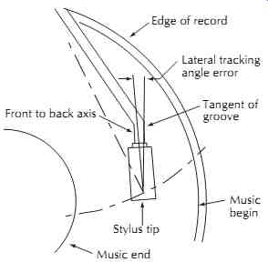
FIG. 10. Geometry of a modern tonearm.
Lateral tracking angle error Tangent of groove Music begin Stylus tip Music end Front to back axis Edge of record
=========
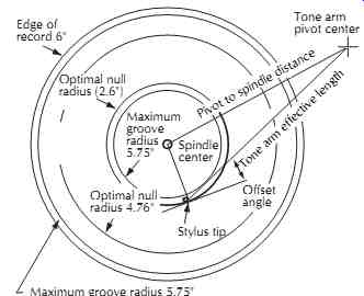
FIG. 11. Relationship of the lateral components of a tonearm.
Edge of record 6" Tone arm pivot center; Optimal null radius (2.6"); Maximum groove radius 5.75" Stylus tip; Offset angle; Maximum groove radius 5.75" Spindle center Optimal null radius 4.76" Pivot to spindle distance; Tone arm effective length
=================
Theoretically, the pivoted tonearm without the offset angle and without any tangent error has to be infinitely long. The tonearm designed by the Rabinoff brothers revived the principle of tangential tracking used by Edison and found application in many turntable systems. In this system the tonearm motion has been achieved using servomechanisms and utilizing various types of arm position sensors. These tangential tracking turntables practically eliminated the tracking error and are quite popular with many hi-fi enthusiasts. There are also drawbacks to this design. Usually, such tonearms cannot be moved as fast as pivoted counterparts, and this may become a handicap in operations when speed of positioning the tonearm is of essence. The advantage of tangential tonearms is that they are shorter, lighter, and can be made more rigid to prevent many tonearm resonances found in some inferior pivoted tonearms.
But the mechanical complexity of tangential tracking tonearms requires the use of modern technology including special integrated circuits and sensors.
Effective Tonearm Length. FIG. 11 defines the turntable platter and spindle location in relationship to the effective tonearm length, which is the distance between the stylus tip and the tonearm pivot.
Modern tonearms have a built-in stop preventing them from moving farther than the locking groove so only three dimensions are of importance: effective tonearm length, vertical pivot-to-spindle distance, and the offset angle.
The accuracy of the cartridge tracking and mounting depends on the effective length of the tonearm. If the effective length of the tonearm is 7.87 inches and it is properly mounted (7.04 inches away from the turntable spindle), the cartridge will track to within +2¼° and -1½°, providing the cartridge is mounted at an offset angle of 27.8°. If the tonearm is longer, the lateral tracking error gets smaller so that the tonearm with the effective length of 10 inches will have a maximum tracking error of less than 1° at the smaller disc radius and a 1.7° error at the maximum radius.
Since the linear speed of the outer grooves is higher and the wavelengths are longer, tracking angle errors have lesser effect on the signal quality. Therefore, tracking errors should be minimized at the inner grooves for consistent quality of playback signal at all radii.
=======
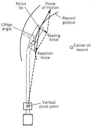
A. Position of the arm on the record
and the forces acting on it.
Stylus tip Offset angle Force of friction Record groove Skating force Reaction force Center of record Vertical pivot point
=====
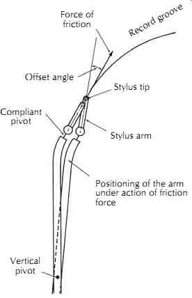
B. Effect of friction on tracking error.
Stylus arm Record groove Force of friction Offset angle Stylus tip Positioning of the arm under action of friction force Vertical pivot Compliant pivot forces acting on it.
FIG. 12. Effects of tonearm geometry. G. Alexandrovich. =====
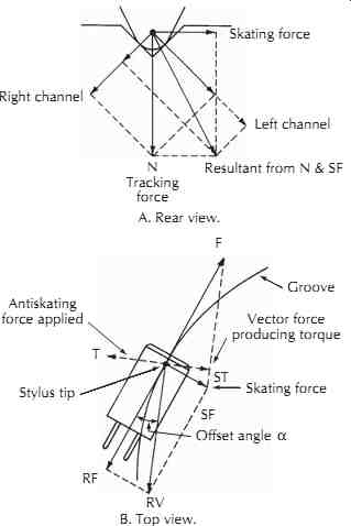
FIG. 13. Skating and antiforces in a record groove.
Skating force; Right channe;l N Tracking force Resultant from N & SF Left channel A. Rear view.
F Groove Vector force producing torque Skating force ST SF RV B. Top view.
RF Stylus tip T Antiskating force applied Offset angle A
=========
Skating Force. Skating force is a force that can upset the best aligned tonearm and cause considerable tracking error. The skating force is the result of tonearm geometry and the friction between the stylus and the record groove. Because of the offset angle and the over hang, one vector of this force pulls the stylus in a direction away from the pivot point of the tonearm and the second vector pulls the tonearm toward the center of the turntable, FIG. 12A. If this skating force is not compensated for, the stylus will be deflected toward the out side of the disc at the angle much greater than the error angle encountered in tracking the groove at different radii, FIG. 12B.
The skating force compensation consists of applying a force to the tonearm that is equal to but opposite in direction to the skating force, FIG. 13. For all practical purposes, the skating force is constant for all radii of the music groove if the tracking error is small and the tonearm alignment is correct. There are slight variations of the skating force due to heavy modulation and groove wall plastic deformation caused by the sharpness of the new stylus, but the largest deviation in skating force is due to the variations in record material. From the study of various materials, it was established that the softest materials produce more friction and larger skating force. Lacquer masters produce up to 25% more friction (i.e., skating force) than vinyl records. Styrene records, today's 45 rpm discs, have approximately 30% less friction than vinyl, requiring less antiskating compensation than vinyl LPs.
There are many different ways to generate the anti skating force. It is incorrect to assume that increasing the drag on the horizontal motion of the tonearm will compensate for skating. Skating force is independent of groove spiraling speed; drag is not. Also, because of the variable pitch common to all present-day recordings, the speed with which the tonearm moves across the record varies and at times may even be zero. Because of this variation, the mechanism that generates the antiskating force should be able to generate a uniform force at all times, regardless of the motion of the tonearm. Anti skating force can be generated by using springs, magnets, weights with pulleys, electrical devices, and mechanical linkages and weights, FIG. 14. Any method to apply the clockwise bias in a horizontal plane to the tonearm to counteract the skating force produces positive results; however, compensation may not be accurate for all types of systems.
The effectiveness of the antiskating force mechanism depends to a high degree on the dynamic behavior of the tonearm. If the tonearm is not dynamically balanced (and most of them are not), any tilt of the turntable may result in a change of skating force, endangering the tracking ability of the pickup. As was previously mentioned, the dynamic balancing of the tonearm implies that the pivot point of the tonearm is also the center of mass. In most modern tonearms this center of weight is shifted toward the cartridge end in order to produce tracking force, FIG. 15. In a dynamically balanced tonearm, tracking force is produced by using either a spring or a permanent or electromagnet (sole noid). A properly dynamically balanced tonearm could play a record with the turntable being in any position and is completely insensitive to jarring of the turntable or floor vibrations.
========
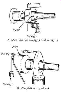
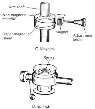
FIG. 14. Different methods of generating antiskating force.
A. Mechanical linkages and weights.
B. Weights and pulleys.
C. Magnets.
D. Springs.
Wire Weight Wire Pulley Weight Arm shaft Non magnetic material Taper magnetic sheet Magnet Adjustment knob Spring
=========
Vertical Tracking Angle. An important adjustment of the tonearm is in positioning the cartridge over the surface of the disc. Cartridges are mounted in tonearms so that the mounting surface of the cartridge is parallel to the record surface, FIG. 16A. Sometimes tilting the cartridge fore or aft results in lower tracking distortion.
Some cartridges are designed to produce the lowest distortion when playing vertical modulation that was recorded at the vertical cutting angle of 25°, FIG. 16B. At the same time most of today's records are cut with the vertical angle of 10°-15°. So in order to reduce the distortion during playback, matching the two angles by moving or tilting the cartridge backward a few degrees may help reduce tracing distortion.
Tonearm Resonance Damping. A Shure Brothers, Inc. study revealed that the warp frequencies of LP records lie in the region from one revolution (0.5 Hz) peaking at 3 Hz and tapering down at 7-8 Hz. Because the audible range of frequencies starts at around 20 Hz, tonearm resonance placed between the warp frequency region and the audible region will allow minimum distortion of the signal due to tonearm bounce. As a result of this research, improvements were made in the tonearms by applying vertical damping to the tonearm. The vertical tonearm motion control was attacked by Discwasher, Inc., by designing a special damping mechanism named Disctracker, which attached to the cartridge. Shure Brothers introduced their stabilizer brush that attached to the cartridge similar to the brushes invented and used by Pickering and Stanton since 1971, except that the Shure stabilizer brush had its pivots filled with damping fluid. These devices helped to various degrees to stabilize the tonearm as the brush cleaned the record groove.
The other approach was to adjust the effective mass of the tonearm by pivoting only the front part of the tonearm and selecting a cartridge with compliance that would match the mass of this portion of the arm, Fig. 17. Dynavector tonearm is an example of such design. Another variation is the design by Sony that employs electronic control of the tonearm motion.
Instead of relying on weights, springs, or magnets, the Sony tonearm uses linear dc electromotors driven, operated, and controlled by electrical signals. Unfortunately, not all functions of the tonearm are controlled automatically and are subject to mis-adjustment.
=====
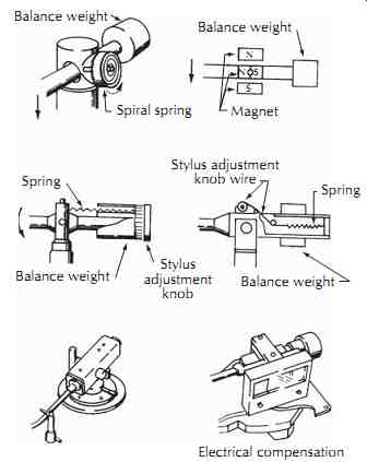
FIG. 15. Examples of how dynamic balance of the tonearm can be achieved.
Balance weight Spiral spring Magnet Balance weight Spring Balance weight Stylus adjustment knob Stylus adjustment knob wire Spring Balance weight Electrical compensation N S N S
======
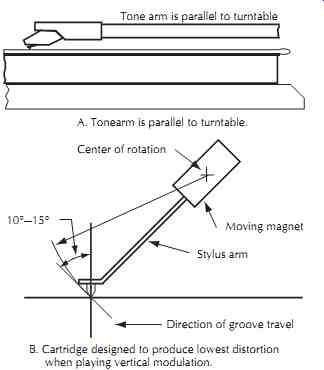
FIG. 16. Schematic representation of the moving system of a pickup, illustrating
the vertical tracking angle.
A. Tonearm is parallel to turntable. B. Cartridge designed to produce lowest distortion when playing vertical modulation.
Tonearm is parallel to turntable; Center of rotation; Moving magnet; Stylus arm; Direction of groove travel 10 degr.-15 degr.
=====
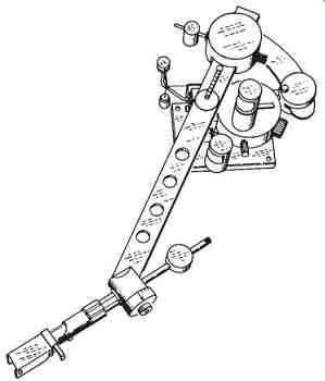
FIG. 17. Dynavector tonearm with pivoted front portion for lower dynamic
tonearm mass. Onlife Research, Inc.