To play a record, the turntable or device to rotate the disc at the required speed is needed. This is the basic requirement for all turntables. The construction and execution of the requirement may differ greatly between the models and the designs of different manufacturers.
The history of evolution of the record drive mechanisms takes us from the days of hand-cranked cylinder machines, through the age of spring-wound phono graphs with mechanical governors for speed control, and into the age of electrically driven machines with electronic control. Today the accuracy of turntable speed is measured in small fractions of 1% in deviation from the desired speed.
1 Drive Systems
Turntables are driven by electric motors. The method by which the power from the motor is transferred to the turntable platter classifies the drive mechanism. The turntable platters can be belt driven, puck or idler driven, and driven direct.
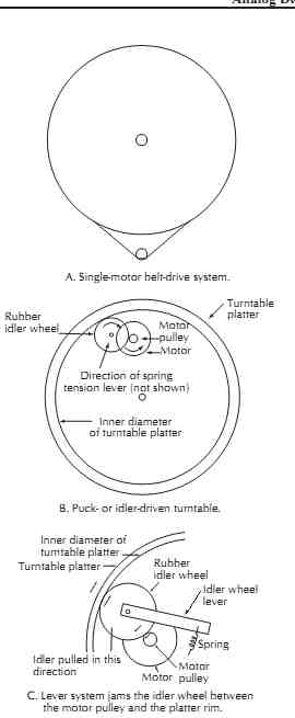
The first category, the belt-driven type, encompasses all models that have motors mounted to the side of the platter with the belt stretched over the motor pulley and outer rim of the platter, FIG. 4A. Some platter designs have an additional internal rim to hide and to protect the belt.
Many turntables have synchronous motors or motors with some type of speed control mechanism, such as a centrifugal switch that disconnects the power to the motor when the speed exceeds the preset value. The later types of motors are usually low-voltage, battery-driven motors used in portable equipment. Also, in portable turntables there is electrical feedback to control the speed of the low-voltage motor.
Another version of the same idea uses a low-voltage ac motor driven by a self-contained crystal-controlled oscillator allowing variation of the speed of the platter and achievement of great speed precision. The only source of speed variation can come from belt slippage or a defective belt. Belt-driven turntables are normally the quietest turntables. The speed selection of the belt-driven turntable can be accomplished either by changing the speed of the motor or by having the stepped pulley on the motor and by shifting the belt from one pulley onto another.
The second type of turntable is a puck-driven or idler-driven turntable, FIG. 4B. The coupling between the platter and the motor shaft is achieved through the intermediate idler wheel or puck, which has the outer edge covered with neoprene rubber or polyurethane for positive drive and to isolate the motor vibration from the platter. The idler wheel rotates on the shaft that is attached to a sliding bracket. When one side of the idler pulley (or puck) is in contact with the inner side of the rim of the platter and on the other side with the motor shaft, the idler wheel will transmit the motor rotation to the turntable platter. The mechanism is designed so when the motor is turned off the idler wheel retracts away from the motor shaft to protect the rubber ridge from forming a flat spot.
The advantage of the rim drive is that it provides positive torque to the platter, and if the motor is strong enough, it can bring the turntable to the desired speed almost instantly. The mechanism is simple, and it is the most reliable type of drive. Unfortunately it is also the noisiest because of the positive coupling between the motor and the platter idler or puck that transmits a certain amount of the motor vibrations to the platter and consequently to the record, as shown in FIG. 4C.
The third kind of turntable drive is the direct drive where the motor drives the shaft of the platter directly.
There are also variations of the design. Some turntable designs are very sophisticated, using the platter itself as a rotor of the motor and drive is provided by the self-contained, quartz-controlled oscillator. The motion is extremely accurate and the speed of rotation may be displayed on the digital display, which is part of the control panel. There is also a weak point in this seemingly perfect drive. Because of the slow speed at which the turntable rotates, and because the motor has a finite number of poles, there is a slight cogging action in the platter motion, which may manifest itself with increased loads. This handicap is only related to turntable platters with fairly small mass and small moments of inertia. If the platter is heavy, it will overcome this problem.
The performance of the turntable depends very little on the type of drive used but more on the correct execution of the design by understanding the problems involved. The ideal turntable should have the following properties:
• It will start fast without hesitation.
• It will rotate with exact speed without variations.
• There will be no motor noises or vibrations heard while the system is in operation, they will not be transmitted to the platter.
• The turntable should be adequately shock mounted and isolated from the surface on which it sits to prevent the transmission of rumble and vibrations from the room. These loud sounds can actually shake the platter and the tonearm.
• The platter should be treated against ringing either by using a turntable mat with damping properties or by undercoating the platter.
• The turntable must be easy to maintain and to repair.
Not many turntables meet all these criteria; there fore, in order to know how to evaluate the unit, it is important to know how they work.
======

FIG. 4. Various types of drive mechanisms. A. Single-motor belt-drive system.
B. Puck- or idler-driven turntable. C. Lever system jams the idler wheel between
the motor pulley and the platter rim.
COMPONENTS include: Motor; Motor pulley; Turntable platter; Inner diameter of turntable platter; Rubber idler wheel; Spring; Idler wheel lever; Rubber idler wheel; Turntable platter; Motor pulley; Motor; Direction of spring tension lever (not shown); Inner diameter of turntable platter; Idler pulled in this direction
=======
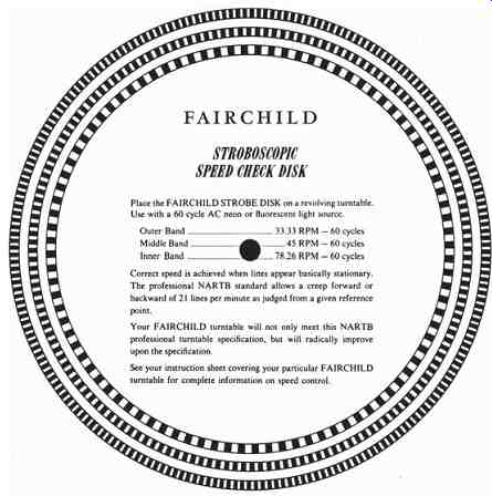
Speed of Rotation. Before evaluating the entire system, there are tests that can be performed on the turntable alone. The first one is speed of rotation. There are many ways of checking the speed of rotation, but the simplest one is by using the stroboscopic disc.
A stroboscopic disc is a circular disc containing a number of black-and-white bars, which are used for checking the speed of turntables and other rotating machines, Fig. 5. The disc is placed on the turntable, and the bars are observed under a fluorescent or neon light source fed from the normal ac lighting circuits.
When the speed of the turntable is correct, the black bars appear to stand still. If the table is turning too fast, the bars speed up and drift in the direction of rotation.
When running slow, the reverse takes place. Stroboscopic bars may be painted around the rim of a turntable and illuminated by a 115 Vac neon light mounted close to the table edge for constant observation. The equation for calculating the number of bars on a 60 Hz stroboscopic disc is:
bars = 2f60/ rpm
where, f is the frequency of the strobe light used to observe the bars,
rpm is the speed of the turntable in revolutions per minute.
Starting Time. Starting time is the time it takes for the platter to reach its operating speed from a complete stop. This time period is important to know for professionals who have to begin playing the song or selection at the exact moment. To check the starting time requires either a stop watch or timing device and a strobe disc or the test record. As soon as the lines on the strobe disc appear stationary, the turntable has reached its operating speed. In playing the record test tone, the pitch changes as the correct speed is attained. Starting time may vary anywhere from a fraction of a second to two or more seconds, depending on the construction of the turntable.
Turntables used by disc jockeys have to start as fast as possible without overshoot, which means that the speed should not, even for a moment, exceed the desired speed. If this overshoot occurs as the program material is already being transmitted, the variations of the speed will be most objectionable.

FIG. 5. A stroboscopic disc used for checking the rotational speed of a turntable.
Fairchild Recording Equipment Corp.
Acoustical Noise. The third test concerns the acoustical noise the motor and the turntable are producing.
Normally, this test can be easily performed in a quiet listening room when everything is turned off and only the turntable is energized. If the turntable noise is clearly heard and it overshadows the normal room noise, turntable drive is below an acceptable performance level. A second part of the same test is conducted when the turntable is turned off and the system is adjusted to a normal listening level. When the record with the quiet groove is placed on the turntable, a slight hiss can be heard when putting your ear to the loud speakers. When the record with the quiet groove is placed on the turntable and the stylus is placed into the groove, listening to the increase in noise will show the extent to which the turntable transmits the building rumble. If the power to the turntable is turned on, the noise contributed by the motor drive can be measured.
During this test, slightly tapping the base of the turn table can determine if the shock mounting is adequate and whether or not loud music will add coloration to the signal being reproduced. In summary, what is required from the good turntable is that it reproduces only what is recorded on the disc and is insensitive to all other sources of vibration.
2 Turntable Design in the 21st Century
One of the most important features of turntable design is the ability to keep noise and rumble created by motors and bearings from being picked up by the cartridge stylus. Many inexpensive turntables have a direct drive between the motor and the platter and inexpensive bearings, allowing motor noise and vibration to be transmitted to the platter and then to the cartridge stylus.
Remember, it doesn't make any difference to the signal whether it comes from the stylus moving versus the disc or the disc moving versus the stylus.
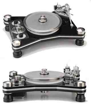
VPI turntables, FIG. 6 use inverted bearings instead of conventional bearings. In this design the bearing assembly is in the platter rather than in a bearing well below the platter. The spindle and ball are attached to the chassis and the bearing well is inverted and placed in the platter itself. With this design the drive belt pulls through the center of the bearing assembly rather than many inches away from the center of the assembly, reducing teeter-totter effects to near zero for better stability.
All motor assemblies are completely separated from the turntable platter and tonearm, so there is no mechanical connection between the motor and the chassis except through the belt. This gives much lower noise levels due to isolation from the source of noise.
The VPI HR-X turntable uses a dual motor flywheel assembly to drive the platter. Two synchronous motors, driven by a perfect sine-wave ac power supply, drive a 14 lb flywheel spinning at 300 rpm, which in turn drives the platter. In this configuration the platter is driven by a non-electromotive source as opposed to other tables that are driven by the motor or combination of motors.
Running the platter with no motor or multiple motors produces a velvety black background and perfect speed stability.

FIG. 6. High-quality noiseless turntable. VPI Industries, Inc.