3.7 Erase Heads
A major advantage of magnetic tape recording is the ability to erase easily and reuse the magnetic tape.
Although physical wear may eventually degrade the performance of the tape, the magnetic properties of the tape never wear out.
Erasure of the tape can be accomplished by remagnetizing the tape with either a very strong static field or a very strong alternating field. For audio applications the alternating field, which produces a completely random flux pattern that is very quiet, is used exclusively.
A very large electromagnet, known as a bulk eraser or degausser, is used for rapid erasure of an entire reel of tape, FIG. 28. The coil and core of the degausser are similar to a large recording head. The very strong flux field created across the eraser gap penetrates the magnetic tape, driving the magnetic particles to complete saturation. Any magnetic patterns on the tape are completely erased when all the tape particles are alternately saturated in one direction and then the other by the changing field.
To leave the tape in a neutral stage, the strength of the erasing field must gradually decrease from hard saturation to zero. A common technique is to move the tape slowly away from the eraser so that the 60 Hz excitation field will drop gradually from one cycle to the next.
A few degausser models include control devices that gradually reduce the current in the eraser coil to zero, thereby eliminating the need for the operator to move the reel. Other models contain motor-driven actuators that slowly remove the tape from the field automatically.
A dc current or permanent magnet can also be used to erase unwanted signals from the tape, but the tape particles will not be left in a neutral state. A dc-erased tape will usually produce a very noisy recording that contains high levels of even-order harmonic distortion components.
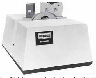
FIG. 28. Tape eraser. Courtesy Taber Manufacturing & Engineering Co.
Selective erasure of small portions of a reel of tape requires the use of an erase head on the tape recorder.
The function of the head is similar to the bulk eraser in that the tape is slowly withdrawn from a saturating ac flux field. For a tape speed of 30 in/s (76 cm/s) and a typical decay length of the erase head field of 0.005 in (125 µm), the drop from saturation to zero occurs in 0.17 ms. If the tape is to experience at least 20 complete cycles during the decay, the erase frequency must be:
ferase = no. of cycles/decay of time (eqn. 10)
A conventional coil-and-core head that has a very long gap can produce the long flux field required for erasure. Although such heads will produce approximately 50 dB of erasure, some of the original signal will still remain. A second pass over the erase head will provide the additional erasure that is required to erase the unwanted signal completely.
The reason for the incomplete erasure is a phenomenon known as gap jumping. As the tape leaves the saturation zone of the erase gap, the flux level experienced by the tape particles will pass through a level that creates a recording zone similar to the trapping plane of the record head. Any audio variations in the erase field would be recorded at this point. Such audio variations are created by the unerased program that is starting to enter the erase field at the other side of the gap. This incoming flux adds to the erase head flux, creating an unwanted recording at the trailing edge of the erase field just as if the audio signal had jumped across the gap.
Complete erasure can be achieved without multiple passes if the erase head contains two magnetically isolated gaps. The tape is erased by the first gap, and then immediately re-erased by the second gap. A wide center spacer isolates the two gaps so that flux cannot jump both gaps.
Although both bulk erasers and erase heads are capable of completely erasing all recorded material from a tape, the residual noise level left by the erase head will be slightly higher than the virgin-tape level achieved by the bulk eraser. Possible sources of this excess noise include small changes in the erase field caused by the tape-to-head contact variations, the tape particle-to-particle magnetic variations, and the recording of Barkhausen noise from the erase core. The record head biasing field also produces similar increases in the noise level. The excess noise perceived by a listener due to the erase and record heads may rise as high as 6 dB above the virgin-tape noise floor.
3.8 Head Degaussing (Demagnetizing)
Early tape recorders used permanent magnets rather than an ac high-frequency signal to bias the tape so that small signals could be recorded without high distortion.
These fixed magnetic fields produced a very high back ground noise level that severely limited the SNR of the taped recording. The introduction of ac bias upgraded the tape recorder from a voice-grade recording instrument to a true high fidelity recorder for music.
Modern recorders all use ac bias, but occasionally the background noise on a tape will be well above the normal level. The culprit is usually a permanently magnetized head, guide, or capstan that is acting like one of the old biasing magnets. The problem is most commonly created by touching a magnetized tool such as a screwdriver or razor blade to a component in the tape path. On rare occasions a faulty electronic circuit will create a dc current in one of the heads, leaving a residual magnetic field. (Loud clicks or thumps may be symptoms of dc currents.)
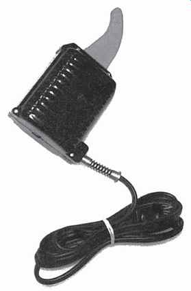
Since there are no commonly available instruments which can detect the very small magnetic fields which will result in noise, the best strategy is to frequently demagnetize all magnetic components in the tape path with a head degausser, FIG. 29.
The head degausser in FIG. 29 is an electromagnet with an extended core. The extension probe conducts an alternating magnetic flux generated in the coil to the tip of the probe. The probe is passed close to the magnetic components on the tape deck so that the alternating flux can flood the components. The actual demagnetizing occurs as the probe is slowly withdrawn from the component, creating the gradually decreasing alternating magnetic field mentioned previously in the discussion of bulk degaussers and erase heads.
Caution! Before using a head degausser, always verify that the tip of the probe is covered by a soft material that will not scratch the face of the magnetic heads.
If necessary, wrap the tip with vinyl electrical tape or a similar tape.
Degauss the heads and other steel tape-guiding parts with a commercial-grade head degausser as follows:
1. Although a typical head degausser will not disturb a recorded tape that is more than a few inches from the degausser, always remove all tapes from the vicinity of the transport prior to energizing the degausser.
2. Hold the degausser at least 1 ft from the tape trans port when applying power to the degausser. The degausser will produce a large voltage in the play back and record heads, which will probably not damage the respective electronics but will certainly "peg" any analog meters in the circuit. Turn off the power to the recorder before using the degausser.
3. Move the degausser slowly and smoothly from bottom to top along the gap line of each head, moving at a rate of approximately 1 _ _ in/s (3 mm/s). At the top of the head, smoothly withdraw the degausser 6 inches (15 cm) and then move smoothly to the next item to be degaussed.
4. To be safe, move the degausser at least 3 ft (1 m) away from the transport before disconnecting the power from the degausser.
5. Multiple degaussing passes on a component do not improve the quality of the results. A single slow, smooth pass is adequate.
The rapid collapse of the magnetic degaussing field at turnoff can easily undo all of the benefits of degaussing if the degausser has not been pulled away sufficiently. (For this reason, avoid degaussers that have momentary power switches that might be accidentally released in the middle of the degaussing routine.)
3.9 Tape Components
Modern magnetic tape consists of a powder of very small magnetic particles, which has been glued to one surface of a plastic substrate or base film. The backside of the substrate is coated with a very thin layer of carbon particles to improve winding characteristics and to reduce the buildup of static electricity.
3.9.1 Base Films
Although several base film materials were used in the past, including paper and acetate film, virtually all tape manufactured today uses polyester film (polyethylene terephthalate) such as Dupont's Mylar . Polyester is not only extremely strong and tear-resistant, but it is also relatively stable with respect to changes in temperature and humidity.
Depending on the intended application, the nominal base film thickness ranges from 1.4 mils (35 µm) for heavy-duty professional tapes down to a scant 0.25 mil (6.25 µm) for a C-120 cassette. To achieve reliable performance with these very thin films, the film must be not only very thin but also uniform in thickness from end to end and from edge to edge.
To enhance the strength of the thin base films used for cassettes, the polyester is pre-stretched or Tensilized.
Although Tensilized tapes are more resistant to stretching than normal tapes, residual stresses that result from the Tensilizing process can produce physical distortion of the tape. For thin, narrow tapes these distortions are satisfactorily flattened out at the record and playback heads. The thicker, wider tapes used for professional formats, which would manifest severe contact problems due to these distortions, are considered to be strong enough without Tensilizing to provide adequate performance.
3.9.2 Binders
The glue or binder that holds the magnetic particles to the base film is a necessary evil that makes no active contribution to the magnetic performance of the tape.
The use of new high-strength binders containing urethanes has improved both the durability and the recording characteristics of recent tapes.
The magnetic characteristics of the magnetic particles never wear out. The particles can be recorded and/or reproduced an unlimited number of times without any performance degradation.
The useful life of the tape is determined by three factors-the inherent strength of the tape, the amount of physical wear caused by the tape transport, and the performance required by the application. A typical test to measure the life of the tape would consist of many repetitive cycles on the intended transport while monitoring the gradual (hopefully) drop in playback level at the shortest wavelength of interest. When these losses exceed the application's requirements, the tape is worn out.
Some specialized audio transports designed for repetitive playback are capable of making over a quarter of a million passes on a tape. On the other hand, a poorly maintained studio recorder can destroy a master tape in ten passes or less! In general, if the abrasive forces exerted by the transport on the tape are well below the inherent strength of the binder, the tape will last virtually indefinitely. Any increase in the abrasive force due to dirty contact surfaces, excessive tape tension, or poorly designed tape guiding will accelerate the wear.
A very rapid catastrophic failure will occur once the abrasion force becomes sufficient to build up a small clump of debris on a contact surface. The friction between the debris and the tape surface is very high due to both the similarity of materials and the high pressure exerted by the tip of the clump as it pushes on the tape.
The binder is overwhelmed, causing the clump to grow rapidly to the point at which the tape will show an obvious scratch or crease. If this situation should arise, the source of the problem should be corrected, and a copy of the damaged tape should be used for subsequent work.
From the magnetic performance standpoint, the combination of smoother magnetic particles and newer binders has enabled the tape manufacturers to use a smaller quantity of binder material to affix the magnetic particles. The ratio of useful particles to the magnetically inert binder rose from approximately 40% by volume for typical mastering tapes in 1970 to approximately 60% in 1980 with virtually no improvement since then. This improved magnetic density yields a higher maximum output for a given particle type and coating thickness.
3.9.3 Magnetic Particles
The ultimate performance of a tape recorder is determined not by the tape drive, heads, or electronics, but rather by the physical and magnetic characteristics of the magnetic particles of the tape. If basic performance parameters such as maximum output levels, noise, and distortion are truly determined only by the tape, the recorder is said to be tape limited. As a practical rule of thumb, if the noise and distortion products of the recorder are at least 10 dB lower than the products produced by the tape, the overall performance of the machine and tape will be within 0.5 dB of the theoretical levels of the tape alone.
Of primary importance in magnetic recording is the ability of each magnetic tape particle to assume and retain a magnetic pattern. These particles are chosen for their ability to maintain a magnetic field along one preferred direction or axis, permitting alignment of the particles for maximum performance. The amount of preferred orientation or anisotropy in the material depends on the nature and crystalline structure of the particles.
The shape of the particles determines the degree of physical alignment that can be achieved during the coating process. Smooth cylindrical or spherical particles that have no jagged edges or branches can be densely packed, yielding maximum output level.
The size of the particles is determined by the crystal line structure of each material. The residual noise of the tape decreases as the particles become smaller. Small particles with high anisotropy are therefore most desirable. Typical iron oxide magnetic particles for recording tape are cigar-shaped particles with a length-to-width ratio in the range of 4:1 to 8:1.
The newest recording products are abandoning particulate coatings in favor of thin layers that are plated or evaporated onto the surface of the plastic. These very thin layers of high coercivity materials are ideal for very short video wavelengths or very high digital bit densities. The new technology brings with it a whole new set of problems such as coating durability and how to include adequate lubrication in the metallic coating.
Coercivity. The coercivity is a measure of the magnetic force required to cause the tape particles to change magnetic polarity. High coercivity particles are more difficult to bias, record, and erase. On the beneficial side, they are also better able to resist external influences due to neighboring particles after recording, reducing the smearing of short-wavelength signals during storage.
Retentivity and Remanence. If the coercivity is considered to be the input drive, then the retentivity and remanence are the output of magnetism left in the tape.
Retentivity measures the maximum output per unit volume of coating cross section; remanence (remanent flux), which is the output per ¼ inch of tape width, varies not only with retentivity, but also with coating thickness. Remanence specifications should be used to compare the maximum long-wavelength outputs of different tape types.
3.10 Magnetic Performance Curves
The input-output relationship for typical magnetic materials is very nonlinear. As shown in FIG. 30A, the magnetization characteristic curve can be broken into three zones. For low excitation levels, the initial output is very small and nonlinear. As the excitation increases, a fairly linear region is encountered, which produces low distortions. As the level continues to increase, the magnetic particles finally become fully magnetized or saturated. Further increase at the input yields no more magnetization in the material.
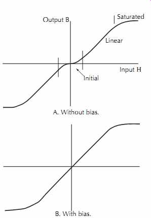
FIG. 30. Tape transfer characteristics.
The nonlinear initial region must be avoided in audio recording if low distortion is to be achieved. The high-frequency bias signal provides enough excitation to jolt the magnetic particles into an active state. Optimizing the bias level yields the much more linear transfer characteristic of FIG. 30B.
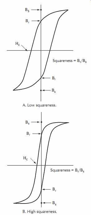
Another representation of the magnetic characteristics is given by the %_+ curves of the tape, as shown in FIG. 31. The curves show the amount of magnetic flux density created within the magnetic material by a cyclically varying intensity of applied magnetic excitation. Since the particles store part of the magnetic field, the path for increasing excitation differs from the decay path for decreasing excitation.
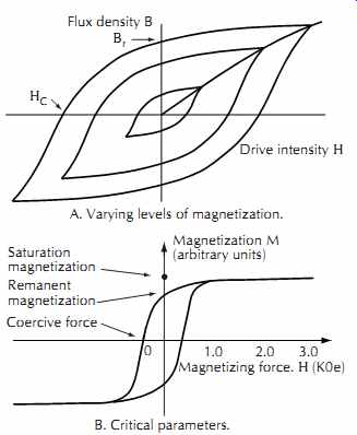
FIG. 31. B-H curves. A. Varying levels of magnetization. B. Critical parameters.
Magnetic recording tapes are typically characterized by the coercivity and retentivity described previously.
These points on the %_+ curve for full saturation are indicated by +c and %r, respectively.
A figure of merit called squareness is commonly used to indicate the uniformity of the magnetic switching characteristics of magnetic coatings. As shown in FIG. 32, the squareness is the ratio of the remanent output value where the curve crosses the vertical axis to the saturated output. A perfect squareness of 1.0 would mean that every particle switched at exactly the same excitation level, yielding maximum output level and low distortion at high output levels.
The squareness ratio improves as more and more particles are aligned in parallel with the flux lines produced by the record head. The ideal case would be if all particles were exactly the same size with a perfect needle shape and all of the particles were stacked tightly like cordwood.
The early oxides had many branches or dendrites stick out of the sides of the needles. The dendrites interfered with the uniform packing of the particles, reducing the overall ratio of magnetic particles to binder. Later highly orientable particles (HOP) with reduced dendrites improved the packing factor. Additional work in coating techniques took advantage of the liquid flow of the coating during application to the base film to align the particles, a technique known as rheological orientation.
As a result of these improvements, squareness ratios have increased dramatically. Over the past 30 years the squareness has improved from 0.8 to better than 0.9 for the best current audio tapes. This improvement translates to more available output and less harmonic distortion from the tape without requiring any increase in bias or record signal.
Table 5 summarizes the characteristics of several of the particles used for magnetic tapes.
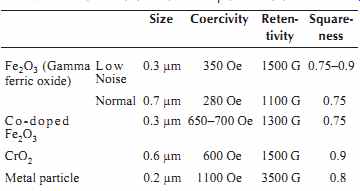
Table 5. Characteristics of Tape Particles
3.11 Magnetic Tape Specifications
The performance of a magnetic tape involves many parameters such as maximum output level, distortion, noise, print through, and frequency response. As a result, the data sheet that characterizes this performance must include many operating characteristics. The user must be very careful, however, to determine the test conditions under which the data is derived, including record head gap length, tape speed, operating level, and equalization.
One form for presenting this data is shown in Table 6. The data entries are measured for one specific recommended bias setting. Some of the values, such as sensitivity at long and short wavelengths, are comparisons to the performance of a standardized reference tape. The notes contain important information defining the test conditions used to derive the data.
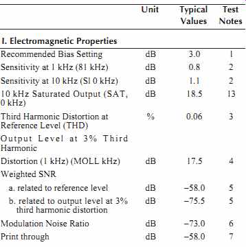
-------- Table 6. Tabular Tape Specifications
Test Notes 1.
1. Recommended bias setting is determined by adjusting the bias current for maximum sensitivity at 10 kHz and then increasing the bias until the sensitivity changes by 3.0 dB.
The adjustments made with a playback reference approximately 20 dB below reference level. The recommended bias setting corresponds to low third harmonic distortion and high output at 1 kHz.
2. Sensitivity is a measure of the output level compared to a standard reference tape A342D, when the recording is made at a constant input voltage approximately 20 dB below reference level and at the recommended bias setting.
3. Third harmonic distortion is the ratio between the level of the third order harmonic and the fundamental frequency (1 kHz) expressed in percent when recorded at reference level and at the recommended bias setting.
4. Output level at 3% third harmonic distortion is a measure of the output level capabilities of a tape at 1 kHz when recorded at 3% third harmonic distortion and at the recommended bias setting.
5. Weighted signal-to-noise ratio is defined as the ratio in dB between the 1 kHz output at reference level or at 3% third harmonic distortion and the ASA weighted (NAB standard) noise level. The noise measurement is made with the recommended bias and without input signal.
6. Modulation noise ratio is defined as the difference in amplitude between a 1.0 kHz signal level and its noise skirt at 800 Hz with a bandwidth of 10 Hz. The recording is made at reference level and the recommended bias.
7. Print through is the level of the accidental printing effect due to a signal recorded on an adjacent layer of tape. The printing signal is recorded at 1 kHz at reference level and the tape is held at 70q F for 24 hours.
8. Coercivity is the magnetic field required to reduce the magnetization of a saturated magnetic specimen to zero. The coercivity is a direct measure of the bias current requirement of a tape. Retentivity is the maximum remanent magnetization possible in a magnetic material. The long wavelength saturated output is directly proportional to the retentivity.
Coercivity and retentivity values are obtained from a 60 Hz B-H loop tester with 1000 Oersted field calibrated to that maintained by the National Bureau of Standards.
9. Thickness measurements are made on Standard Gauges, 8000 Series, Smart Box.
10. Yield strength is defined as the force that produces 3% elongation of the samples. The measurement is made on an Instron tensile tester at a jaw separation of 5 inches and a crosshead speed of 2 inches per minute.
11. Breaking strength is the ultimate tensile strength indicating the force at which the tape breaks and is measured on an Instron tensile tester at a jaw separation of 5 inches and a crosshead speed of 2 inches per minute.
12. Backcoating resistivity relates to the tendency of magnetic tape to retain static charge. A resistivity value of 5 × 10^4 ohms per square is sufficiently low to prevent static buildup which might result in tape damage on high-speed bin loop duplicating systems or in normal use at low humidity conditions.
13. See bias curves.
Specifications are subject to change without notice.
--------
In contrast, the graphical data in FIG. 33 depicts how the various values change as the bias value is adjusted over a range of 16 dB. All values are absolute values without any comparisons to a reference tape. The parameters of the recorder used for testing are shown above the graph.

FIG. 33. Tape performance data in graphical form.
The bias point recommended by the tape's manufacturer is the 0 dB value on the bottom scale. This value is a compromise value determined by simultaneously evaluating the distortion, noise, and maximum output levels for each bias setting.
There are two common methods used for setting the bias level. One technique is to adjust the bias while recording a long wavelength such as 1 kHz. The bias is increased until the recorded signal peaks. The bias level is then further increased until the recorded signal drops by 0.5 dB.
A second technique is to use a short wavelength, typically 1.5 mils, and adjust for a significant amount of overbias. The bias is increased until the recorded signal peaks. The bias is then further increased until the recorded signal decreases from peak by several dB.
How do these two techniques compare? Find the sensitivity curves S1 and S10 near the center of the graph.
These curves show how the 1 kHz and 10 kHz signals will change in level as the bias is increased. Note that the S1 curve is very flat, changing only ¼ dB from peak over a bias range of 5 dB. In comparison, the S10 curve is falling at a rate of approximately 1 dB/dB of bias increase.
The flat shape of the S1 curve provides very little signal drop for a rather large bias change. A 0.1 dB error in the signal level adjustment, perhaps due to a sticky meter, may change the 10 kHz sensitivity by 2 dB or 3 dB. This error would require an additional record equalization boost of 2-3 dB to correct the overall response.
In contrast, the rapid signal level change when using a 10 kHz signal gives a much more precise adjustment and better uniformity from track to track. It is clear that both techniques are trying to achieve the same adjustment, but the short wavelength technique offers much better resolution.
This technique can be a trap for those who don't understand what is actually happening. The S1 and S10 curves are really curves for the specific wavelengths of 15 mils and 1.5 mils, respectively. If the tape speed is doubled, these curves will now represent performance at 2 kHz and 20 kHz. The 15 in/s overbias specifications for 10 kHz must not be used at any other speed! For example, at 30 in/s the S10 curve of the example tape has a downward slope of only 0.5 dB/dB of bias. Why? Because the wavelength is 3 mils, not the 1.5 mils of the previous example at 15 in/s. The manufacturer recommends only 1.5 dB of overbias at 10 kHz and 15 in/s. It is important to use the same wavelength at all speeds by shifting the test frequency to 20 kHz or 5 kHz at 30 in/s and 7.5 in/s, respectively.
As mentioned previously, the test data is very dependent on the characteristics of the recorder used during the testing. In particular, the shape of the S10 curve varies greatly with changes in the record head gap length. Table 7 illustrates how this gap length affects the recommended amount of overbias.

Table 7. Short-Wavelength Dependence on Record Gap Length
3.12 Problems with Older Tapes
The archives of American tape recordings contain tapes that are up to 50 years old. Unfortunately, many of these tapes have problems that could easily damage or destroy their recordings. Some of these problems can be corrected, but others are irreparable.
3.12.1 Adhesion and Peeling Oxide
Adhesion is the binding force that firmly holds the oxide layer onto the plastic substrate. Two simple tests can be used to evaluate the strength of the adhesion-the Scotch tape test and the sharp edge test.
The Scotch tape test tries to rip the oxide from the plastic substrate by brute force. Start with a strip of Scotch Brand Magic Mending tape several inches long.
Adhere about 3 inches of the sticky tape to the oxide surface of the recording tape. Rub the joint to assure complete binding of the tapes. The test is to peel back the sticky tape with a quick jerk parallel to the tape. If the sticky tape comes off cleanly, the adhesion is good.
If the oxide layer delaminates and peels off with the sticky tape, the adhesion is poor.
The second adhesion test utilizes a blunt edge to create a very sharp bend in the tape. Find a sharp perpendicular edge on a desk or a piece of plastic ruler that has no rounding radius. Place the backside of the tape sample against the sharp edge. Pull on the ends of the tape to establish a firm tension in the tape. While maintaining the tension, drag the tape over the edge in a 90q bend. If the oxide does not loosen from the backing, the tape passes the test. A poorly adhered tape may suffer complete delamination of the oxide, with a solid band of oxide peeling off and shooting away from the backing.
3.12.2 Brittleness
The polyester base films and urethane binders of modern tapes remain flexible under all normal circum stances. The base films and oxide layers of earlier tapes, however, could become brittle. Plasticizers were included in the binders and the acetate backing to provide flexibility in the tape. Unfortunately, these plasticizers can harden with age, causing the tape to become brittle. Harsh storage conditions can accelerate the breakdown of the plasticizers.
Brittleness cannot be reversed. The only remedy is to use a tape transport that is extremely gentle on the tape.
Choose a transport with dynamic braking rather than harsh mechanical brakes. A transport with constant tape tension can be set for the lowest practical tape tension.
Some decks also feature gentle start capability that ramps the capstan up to speed to smoothly accelerate the tape rather than just slamming a pinch roller onto a running capstan.
3.12.3 Splice Failures
In the early days, standard Scotch Brand cellophane tape was the only splicing tape. Later on, splicing tapes such as Scotch #41 and #620 were developed with improved characteristics. Although these tapes were fine for day-to-day operations, they have not survived the test of 50 years of storage. For example, the adhesive of both cellophane tape and splicing tape can ooze out and stick to adjacent layers of tape. A common remedy was to apply talcum powder to the sticky oozed adhesive to avoid layer-to-layer adhesion.
With even more time the adhesive can dry out completely, causing the splice to fail. In this case the only remedy is to replace the splicing tape with new tape. The newest splicing tapes, such as blue #67, replace the original latex adhesives with synthetic adhesives that do not ooze or dry out.
The tape operator must be watchful for two problems created by bad splices. First is layer-to-layer adhesion that can produce strong tugs that break older acetate tapes. Second is tape separation at a failed splice. DO NOT run the tape through the recorder at high speed if you suspect either problem may exist. If the tape tugs or separates at high speed, the loose end may be slapped around and broken off before you can stop the spinning reels.
If the tape is old, wind the tape slowly and carefully to examine each splice. Re-splice all splices if there is any hint that the splices may separate. Do not try to remove any of the old splicing tape adhesive that has dried out on the recording tape. Sticky adhesive residue that could bond to adjacent layers, on the other hand, must be removed.
---------------
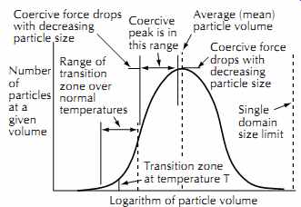
FIG. 34. Particle size distribution.
Coercive force drops with decreasing particle size Coercive peak is in this range Average (mean) particle volume Single domain size limit Range of transition zone over normal temperatures Transition zone at temperature T Logarithm of particle volume Number of particles at a given volume Coercive force drops with decreasing particle size
---------------
3.12.4 Print Through
The energy required to activate a particle to switch magnetic states depends on the size of the particle, with the overall characteristics of a magnetic tape being determined by the average size and characteristics of many particles in the coating. A more detailed analysis of the particles would yield a distribution of sizes, as shown in FIG. 34. Although the majority of the particles cluster around the average value, a small portion of the particles are either much smaller or much larger than the average. The small particles give rise to spontaneous recording as print through; the large particles produce noise bursts.
The small particles require so little activation energy to assume a new magnetization state that even the thermal energy of the particles may provide enough bias to cause the particles to be recorded by the stray magnetic fields due to adjacent layers of recorded material. This spontaneous recording is most evident as pre or post- echo at the beginning and end of a recording.
The strength of the print through image depends on both the percentage of thermal idiots in the coating and the ratio of remanence to coercivity of the tape. The remanence measures the driving force of the signals trying to print through. The coercivity, on the other hand, is the stubbornness of the particles to resist this imprinting.
The effective coercivity of the small particles is diminished because the domain size is sub-optimal, rendering the small particles more susceptible to printing.
The milling process used to provide thorough mixing of the particles, binder, and additives prior to coating is a rather abusive process that can create thermal idiots by fracturing some of the desirable large particles into smaller, low-coercivity particles. Insufficient milling, on the other hand, provides an uneven particle dispersion that creates noise on the tape. The tape manufacturer must strike a compromise that yields both low noise and low print through.
Print through of a signal produces both pre-echoes and post-echoes. The pre-echoes are more troublesome in music, however, since the pre-echoes frequently occur in the quiet passages just before the loud note.
The post-echoes, on the other hand, are frequently masked by the diminishing tail of the musical note and the room reverberation.
Fortunately, the print-through process does not produce equal amounts of pre- and post-echo, but unfortunately the more undesirable pre-print echo is the stronger. The vector magnetization components that arise during the recording process cause the levels of print on the outer adjacent tape layer to be several decibels higher than on the inner adjacent tape layer, as shown in FIG. 35. The more troublesome pre-print echoes on musical selections can therefore be minimized by storing the tape tails out to move the quiet lead-in to the inner layer. This will also bury the louder outer layer print through echo in the decaying signal at the end of the music.
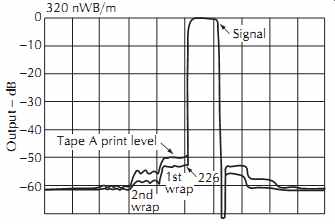
FIG. 35. Pre- and post-echo print through. Courtesy 3M Co., Magnetic Audio/Video
Products Div.
The use of nonmagnetic leader tape between selections is also helpful to eliminate pre-echo on selections that begin with a rapid attack. Be aware, however, that paper leader tape can contain a small amount of magnetic debris that will raise the noise level as the leader passes over the playback head.
The user can take several steps that will minimize the amount of print through. First, the use of thicker base films increases the spacing between layers.
Second, avoiding elevated temperatures and stray magnetic fields during use and storage will decrease the excitation of the thermal idiots. Third, exercising the tape by shuttling the tape from reel to reel several times will partially erase the printed particles. The flexing and rubbing of the tape produce enough activation energy to neutralize some of the printing. For this reason, never copy a stored master tape without exercise. The worst possible print through level exists on the very first pass of the tape. In some cases print through can drop as much as 4-6 dB with five shuttle cycles.
3.12.5 Sticky Shed and Tape Baking
As mentioned earlier, the goal is to attach a maximum number of perfectly stacked and oriented magnetic particles onto the surface of the backing material.
Anything that interferes with this goal by displacing some of the magnetic particles, such as additives for lubrication, fungicides, and static charge reduction, degrade the performance of the tape. Most important in this category is the very binder that holds the particles in place. Every bit of binder displaces some of the useful magnetic particles.
The best choice is to use a very strong binder that can do the job with the minimum amount of glue, allowing space for more magnetic particles. The winner is the highly crosslinked thermoset polymers in use today. Starting around 1970, these binders with a high urethane content gave a big boost to tape performance. Unfortunately, long term experience with these tapes now shows that the binder can break down during storage. The symptoms are a buildup of residue on the head and guides and a tendency for the tape to stick to these residue buildups, in some cases actually dragging the tape to a stop. The popular name for this problem is sticky shed. The problem is usually discussed in terms of binder breakdown, but there appears to be a second major problem related to lubricant oozing that is also present.
Urethane Binder Breakdown. The urethane binder contains long polymer chains that provide the high strength of the binder. Water in the surrounding air enters the tape and breaks the long chains through a process known as hydrolysis.
As a result of the chemical breakdown of the long polymer chains, the binder is weakened enough for the surface of the tape to begin to rub off onto the stationary guides and heads. Depending on the design of the trans port, this residue can clog the heads in just a few seconds. Machines with rotating guides and low tape tensions take longer to clog, but the damage to the tape is still intolerable.
Fortunately, the hydrolysis is somewhat reversible.
Tapes can be baked at a moderate temperature to reverse the hydrolysis and restore strength to the binder.
Although this may seem like a bit of witchcraft, thou sands of baked rolls of archived tapes have proven the technique.
The electric oven must provide a well-controlled temperature of about 120-140°F (50-60°C). Large dehydrators or fruit dryers are popular because of their size and limited temperature range. Only an electric oven should be used. The oven should be preheated and checked for temperature stability with a high-resolution thermometer such as a candy thermometer. The tape, wound onto a metal reel, is placed into the oven horizontally with generous space above, below, and around the reel for air circulation. The tape is baked for 15-20 hours, and then allowed to cool to room temperature undisturbed in the oven.
The baking process creates a low-humidity environment that draws some of the excess water from the tape binder. The short polymer chains may recombine with their neighbors to produce a better bond, but the break down process is not fully reversed.
Lubricant Oozing. The second failure mechanism also involves the binder, but in this case the culprit is the oxide. A change of oxide particles also changes the chemistry needed to make a liquid binder that can:
1. Hold all the magnetic particles in suspension.
2. Be smoothly coated onto a polyester backing material.
3. Have the volatile byproducts evaporated in the drying ovens.
In the early 1970s Phizer introduced a new high-output oxide with excellent signal characteristics, but the particle required a reformulated binder with a low pH in order to meet the above requirements for a usable dispersion. This particle was utilized by 3M in the 226 family of tapes (226, 227, 806, 807, 808, 809) and by Ampex in the 456 family.
The new binder formula included a component that served primarily as a lubricant. Unfortunately, however, this lubricant would migrate to the surface of the tape and concentrate into a sticky residue.
The baking operation described in the previous section warms the concentrated lubricant enough to allow the lubricant to flow and be reabsorbed into the depths of the coating.
Since both types of sticky shed problems are treated by baking, most people who bake tapes don't know for certain which problem they are treating, and if the sticky shed is eliminated, they probably don't care.
How long before a baked tape begins to again exhibit sticky shed? Results will vary depending on the amount of degradation, the tape type and specific batch, the exact baking method, and the operating environment after baking. Reports vary from days to years. Certainly baking provides an adequate window for the tape to be transferred to another medium.
Is there any degradation due to the baking process? The most likely problem is print through caused by the elevated temperature. Print through is a time-dependent problem that peaks out at a maximum value after a long time. Heat accelerates the printing. However, stored tape probably has had enough time for the print through to be near the maximum value before baking. As a result, the additional print through caused by the baking may be negligible. Follow the exercise process described at the end of Section 3.12.4 to minimize the print through before copying the tape.
How can sticky shed be avoided? The rate of hydrolysis depends on the storage conditions. Archival storage at a temperature of 60 F (15°C) and relative humidity of 25% ± 5% is optimal, but few have the luxury of an environmental chamber, so store the tapes in a cool, dry location in the original package standing on edge.
Sticky shed may also produce layer-to-layer adhesion. If you strongly suspect sticky shed, bake the tape before trying any winding operations on a tape trans port. This will avoid the total loss of recorded segments due to oxide being ripped from the tape's plastic backing during spooling.
3.12.6 Squealing Tape
One of the many ingredients in the coating recipe is a small amount of lubricant. Obviously, the tape cannot be too slippery or else the capstan couldn't maintain constant tape speed. Running the tape completely dry, on the other hand, can produce an audible squeal. The tape undergoes a "stick-slip" phenomenon on the stationary guides and head, creating a jerky motion at a high frequency. The irregular motion can even be measured with a scrape flutter meter.
The squeal results from the loss or failure of the original lubricant. The obvious solution is to replace the lubricant. A can of 10-W30 motor oil isn't appropriate, but another common household lubricant, WD-40, is recommended by Quantegy. Quantegy claims that WD-40 is cheap, available, inert to all recorder components, and a very good lubricant. Apply the oil sparingly by lightly wetting a lintless rag or swab with the oil and holding the applicator against the oxide side of the moving tape at the first guide after the supply reel. A bit of experimenting may be required to find the proper amount of oil that is required to eliminate the squeal without causing slippage and speed irregularities. When you are finished using the tape, prepare the tape for storage by passing the tape over a dry applicator in a medium speed fast wind mode. (Use extreme caution on tape transports that have elastomer coatings on the capstan and/or timing rollers. Lightly lubricate the tape while passing the tape directly from the supply reel to the takeup reel, and then dry the tape with a second pass over a dry applicator before threading the tape over the elastomer components.)
