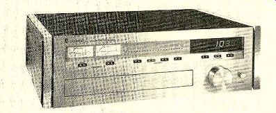
Sherwood Micro/CPU 100 FM tuner
A MICROPROCESSOR, for the benefit of those not familiar with the term, is a large-scale integrated circuit that contains the basic working elements of a digital computer. Given a moderate number of additional components, it can actually become a computer with rather impressive capabilities. Thousands of hobbyists now have personal computers using these devices, and a thriving industry has developed to meet their needs.
Microprocessors are found in many types of products from automobiles to microwave ovens-and in the past year or two in high fidelity components. The first product to use one was a turntable, then a cassette deck, and now we have a remarkable FM tuner from Sherwood, the Micro/CPU 100.
From the outside, the Micro/CPU 100 is instantly recognizable as an FM tuner, with a dial scale calibrated from 88 to 108 MHz located in the usual place at the up per-center of the satin-finish aluminum front panel. As on many tuners and receivers, the word STEREO lights up above the dial scale when a stereo broadcast is received. However, the dial has no pointer, which is the first clue that this is no ordinary tuner.
To the left of the dial are two normal-looking meters labeled SIGNAL and MULTIPATH.
At the lower right of the panel is a large knob, obviously for tuning, and a pushbutton power switch. A hinged door across most of the lower portion of the panel swings down to reveal a number of small knobs and switches whose markings also seem consistent with FM tuner operation.
The first sign of something "completely different" (other than the missing dial pointer) is a black window to the right of the dial and a row of contactors, grouped into nine closely spaced pairs, emerging from the panel below the dial. Two at the left are marked ALPHA and STORE, with the word PROGRAM identifying their joint function. The next four (A, B, C, D) are labeled MEMORY. At the right are three identified as AUTOSCAN, with the center one marked STEREO and the flanking contactors marked LEFT and RIGHT.
The rear panel of the tuner contains few surprises, with two pairs of audio outputs marked FIXED and VARIABLE, a COMPOSITE output (before the multiplex circuit, for use with an external decoder should the FCC approve a system of discrete quadraphonic FM broadcasting), and terminals for 75- and 300-ohm FM antennas. There is a single unswitched a.c. outlet, a fuse, and a small toggle switch marked FREQUENCY-EVEN/ODD.
Rather than go into further detail about what is inside the Micro/CPU 100 (most of which would not be recognizable as a tuner to most people because of the absence of such familiar components as tuning capacitors, coils, and the like), let us examine what hap pens when the tuner is connected to an amplifier and antenna and is switched on.
The black area to the right of the dial lights up to reveal a large digital frequency display with bright red 1/2-inch-high numerals.
Turning the knob causes the expected change in the frequency indication, and stations are tuned in just as with other tuners having a digital frequency readout. It is interesting to note that the tuning knob is not connected to any mechanism, but merely turns a multi-bladed "fan" that interrupts a light beam to signal the tuning operation to the computer.
The frequency display is not just a frequency counter, but is the readout portion of a frequency synthesizer that accurately tunes the set to channel frequencies at 200-kHz spacings (with an accuracy of 0.0024 percent).
When the switch in the rear is set to ODD (the normal condition for this country), the tuner will receive only channels with odd frequencies (for example, 104.3 MHz). In some countries where channel assignments are on even-numbered frequencies, the switch can be set to EVEN, and the tuner will then reach only even frequencies (for example, 104.2 MHz, etc).
It is not necessary to use the knob to tune in stations. A light momentary touch of the LEFT or RIGHT AUTOSCAN contacts causes the tuner to scan electronically down or up the band, stopping when it comes to any station strong enough to overcome the muting threshold. If it reaches the end of the band before finding a station, the tuner returns instantly to the frequency from which it started and resumes scanning in the opposite direction. If it finds nothing there (hardly likely unless no antenna is connected), it returns to the starting frequency and stops. A touch on the center STEREO contact will permit the tuner to stop scanning only on a stereo transmission (a second touch returns it to the stereo/mono mode). When any of the control contacts on the panel is touched, a light appears behind it to show the function is being executed.
So far we have described a tuner not very different from some other synthesized tuners.
The first significant difference comes when, one wishes to use the four MEMORY contacts.
Unlike some tuners whose memory functions depend on punched cards or other physical accessories, the computer in the Micro/CPU 100 is able to store the frequency of a station in one of four memory locations, from which it can be called up at any time by a touch of the corresponding contact, which instantly tunes the tuner to that frequency. For example, to store 93.9 MHz in memory A, tune the set to that frequency, touch the STORE con tact, and touch A. The information remains in the memory indefinitely (even when power is removed from the tuner), but it can be changed at any time by tuning to some other frequency and repeating the process.
This brings us to one of the most startling (the adjective is a fair one) features of the Sherwood Micro/CPU 100-its alphanumeric memory and display, which is best illustrated by a step-by-step description of its use. In the New York area, 93.9 MHz is assigned to WNYC. When it has been tuned in, touching the ALPHA contact causes a letter "A" to appear in the portion of the display area to the left of the station-frequency numerals. Turning the tuning knob now causes that letter to change in sequence through the entire alpha bet, followed by a series of punctuation marks and all the numerals comprising essentially the content of a full typewriter key board. The characters are formed by multiple LED's and are % inch high.
In the case of "WNYC," we stop at the "W" and touch STORE. This causes an "A" to appear to the right of the "W," and we go through the same process until we reach "N." Touching STORE now gives us a display of "WNA," and the process is repeated to form "WNYA" and finally "WNYC." The fourth operation of the store function restores the tuning knob to its normal function.
The Micro/CPU 100 has memories for up to forty-eight sets of call letters, and it is there fore possible, in almost every part of the country, to assign call letters to every receivable station. If one reaches the limit of forty eight and attempts to load another frequency into the memory, the display flashes FULL for a couple of seconds and goes blank. Should one still wish to assign a call to that frequency, it is necessary to erase one set of call letters by tuning to its frequency and touching ALPHA and memory A in sequence.
Behind the front-panel door, from left to right, are knobs for adjusting output level (up to 1.5 volts) and muting threshold, and switches for controlling the MUTING, SELEC TIVITY (the tuner has normal and wide i.f. amplifiers), the AUTO STEREO FILTER (a high-frequency blend circuit that can either come into play automatically when the signal is weak enough to be noisy or can be disabled entirely), STEREO/MONO mode, and DE-EMPHASIS. The normal de-emphasis setting is 75 u-sec (microseconds), but it is internally adjustable to the 50 u-sec used in Europe, and the other setting is the 25 µsec needed with an external Dolby adapter.
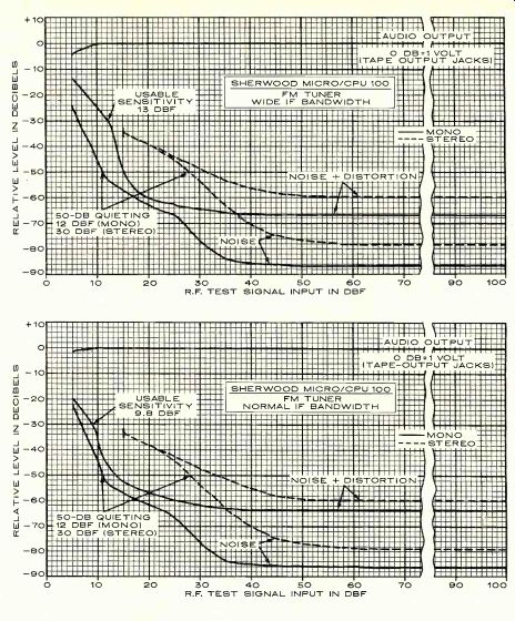
--- R.F. TEST SIGNAL INPUT IN DBF
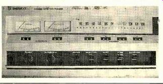
---- Close-up of the Micro/CPU 100's front panel shows the four memory
contacts. The opened panel under the dial reveals the other operating controls.
In case you have been wondering about that pointer-less dial, it has a row of LED's, at 1-MHz intervals, that light up to show approximately where the tuner is set, although the numerical display makes this unnecessary.
The performance specifications of the Sherwood Micro/CPU 100 are, to say the least, excellent. This is not surprising, since no one would be likely to design a tuner with costly state-of-the-art control features without giving it performance to match. Rather than de tail the specifications, we will let our laboratory measurements speak for themselves.
The Sherwood Micro/CPU 100 is 20 inches wide, 6.5 inches high, and 15 inches deep. It is furnished in a black metal cabinet with walnut-grain wooden side plates. The tuner weighs 34 pounds. Price: $2,000.
Laboratory Measurements. Since the Sherwood Micro/CPU 100 can be tuned only in discrete steps, we located a clear channel and tuned our signal generator to the tuner frequency instead of the other way around. Al most all measurements were made twice, using both NORMAL and WIDE i.f. bandwidth, since this can affect many areas of the tuner's performance.
The sensitivity was certainly impressive.
The IHF sensitivity ( NORMAL) was 9.8 dBf or 1.6 microvolts (uV) in mono. In stereo it was 15 dBf (3 µV). The more important 50-dB quieting sensitivity was 12 dBf (2.2 uV) in mono
with 0.7 percent distortion, and in stereo it was 30 dBf (17 uV) with 0.63 percent distortion. In the WIDE i.f. position, the sensitivity figures were essentially the same, the only change being a mono IHF sensitivity reduction to 13 dBf (2.4 uV).
In the NORMAL mode, the distortion at 65 dBf (1,000 uV) input was 0.1 percent in mono and 0.13 percent in stereo.-In the WIDE mode, distortion was slightly less, reading 0.07 percent in mono and still 0.13 percent in stereo.
Stereo distortion, with L- R modulation, was 0.4 percent at 100 Hz, 0.067 percent at 1,000 Hz, and 0.089 percent at 6,000 Hz ( NORMAL). In WIDE, these figures were 0.56, 0.1, and 0.056 percent.
The signal-to-noise ratio (S/N) of the Micro/CPU 100 was phenomenal, far better than we have ever measured before and better than what we had suspected our Sound Technology signal generator was capable of: in mono it was 82.5 dB, and in stereo it was 75 dB. The readings were approximately the same with both bandwidths.
The stereo frequency response was within ±0.3 dB from 30 to 15,000 Hz. The crosstalk (channel separation) with the NORMAL band width was nearly as flat, measuring 45-±1.5 dB from 30 to 5,000 Hz, and with the mini mum separation being 40 dB at 10,000 Hz! In the WIDE setting it was generally similar, except that the separation fell to 36.5 dB be tween 10,000 and 15,000 Hz.
The other tuner-performance measurements ranged from good to almost unbelievable. Capture ratio ( NORMAL) was 1.06 dB at 45 dBf (100 uV) and 1.25 dB at 65 dBf (1,000 4.4N). As expected, it was better in WIDE, reading 0.72 dB at 45 dBf and 0.61 dB at 65 dBf. These are the best have ever measured, but it must be realized that accurate and repeatable capture-ratio measurements below 1 dB are very difficult, if not impossible, to make.
The AM rejection was very good, varying from 68 dB (65 dBf, WIDE) to 72 dB (45 dBf, wide). Image rejection was un-measurably high, being greater than the 106-dB limitation of the test instruments. In NORMAL the alternate-channel selectivity was a very high 87 dB with perfect symmetry about the channel center. In WIDE, it measured 38 dB with a slight asymmetry. The respective adjacent-channel selectivity figures were 8.4 and 4.8 dB. The muting threshold was adjustable from about 15 dBf (3 4.4N) to something in excess of 95 dBf (30,000 uV) with the control at its clock wise limit. The stereo switching threshold was about 15 dBf (3 µV). The pilot-carrier leakage in our sample was relatively high at-62 dB (it Is rated at-80 dB), but this is low enough that it should not cause any problems with external Dolby units or tape recorders. Finally, the tuner hum level was the lowest we have measured to date, -80 dB referred to 100 percent modulation.
Comment. If the Sherwood Micro/CPU 100 had been just an ordinary tuner with the various computer functions added, we would have judged it noteworthy, fun to use, and probably a living-room conversation piece.
But it would hardly have aroused any great enthusiasm in us.
As it is, in addition to its unique control features, this is one of the most impressive tuners-as a tuner-we have ever seen. It is so outstanding in so many ways that it is difficult to avoid the overuse of superlatives in de scribing it. For example, it has an absolutely flat frequency response, with none of the loss of extreme highs that we believe accounts for many of the quality differences heard be tween tuners. Its distortion, like that of some others, is lower than can be measured meaningfully with a Sound Technology signal generator-and there is nothing available at this time that is any better. Its channel separation of typically 45 dB across the full audio range is 10 to 20 dB better than that of any recorded program source, as well as of the FM stations themselves.
Needless to say, there is no possibility of a distortion-producing tuning error with the Micro/CPU. When a station is heard, it is heard properly. The SIGNAL meter has a logarithmic response, giving useful and proportional readings on any receivable signal. The MULTIPATH meter not only works, but it is just about the best of its kind. Unlike almost every other one we have used, this meter does as good a job as an oscilloscope, and it is a lot easier to interpret. Even a small amount of multipath distortion causes a visible meter movement, and when it reads zero, the distortion is really negligible.
The muting (which is significant only in manual or AUTOSCAN tuning) is very good, though there is a tendency for noise bursts to occur when it is set too low, and it is possible to pass by a station if it is set too high. In nor mal use it is absolutely silent, with enough time lag that the knob can be spun to cover the entire FM band without a sound while the tuning is under way.
Perhaps the most surprising thing about this tuner was its noise level, which was 5 to 10 dB lower than we have ever measured before, also 10 to 15 dB lower than on any other tuner). This may or may not be immediately apparent to the listener (it was not to us), but what it really means is that beyond any reasonable doubt the sound quality of the pro grams emerging from this tuner-for better or worse--is determined entirely at the broad cast station.
In case any readers might be concerned about potential servicing and reliability problems of the very complex Micro/CPU, the tuner can actually use its built-in computer to check the performance of its own circuits.
Specially programmed read-only memory (ROM) IC's are available to Sherwood's servicing organizations for this purpose. When one of the IC's on the internal computer board is replaced by one of these special plug in IC's, the various computer circuits are rap idly checked in sequence, and the results are displayed as flashing letters and numbers on the readout panel. Any defective IC is immediately identified by part number on the display. If all is well, the test is completed in less than one minute, and the words TEST DONE flash alternately on the tuner's call-letter display.
Another IC is used in a similar fashion to check the interface between the computer and tuner circuits. It causes the tuner to scan the entire FM band and activates all the touch-
contact functions. The time required to per form these tests is controlled by the "tuning" knob and varies from about 5 seconds to a fraction of one second.
A final demonstration of the tuner's self-test capability is triggered by setting the ODD/ EVEN switch on the rear panel to EVEN. The alphabetical display then shows a message (THE QUICK BROWN FOX JUMPED OVER THE LAZY DOGS BACK), moving from right to left, that checks the ability of each display character to reproduce the entire alphabet.
While these self-test features do not directly help the user, they certainly should help to minimize the time and cost of any repairs that might become necessary. The tuner carries a two-year limited warranty.
As we tested the Sherwood Micro/CPU 100, we were struck by another of its proper ties that is not likely to be detected in normal use. Most FM-tuner tests require rather careful arrangement of input and output signal cables, critical tuning of the signal generator, and a certain amount of fiddling-none of which are spelled out in the instruction manuals or in the standards. In more than twenty years of product evaluation, this is the first FM tuner that we have been able to test like a textbook example. There was absolutely nothing "touchy" or critical about any adjustment or measurement except possibly capture ratio, which is a function of the signal genera tor as much as anything else. The same setting of the signal generator that gave a zero multipath-meter reading also gave lowest distortion and noise and best channel separation, and, unlike the situation with most tuners, none of these normally critical tuning points changed with signal level.
The Sherwood Micro/CPU 100 is one of the most expensive FM tuners you can buy.
Sadly, things being what they are in the broadcast and recording industries, you may not hear much-if any-difference between it and some other fine but far less sophisticated tuners. Given the rapid advances in the state of the audio art--and given the differences in importance that any individual might attach to any particular performance quality-it is risky and perhaps misleading for a reviewer to refer to any product as "the best." Nevertheless, our reaction to the Sherwood Micro/ CPU is that, as of now, it is the best available FM tuner. And it is important to stress that we would have found this tuner just as remarkable even if it lacked its special computer functions.
++++++++++++++
ADS 810 speaker system
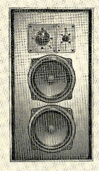
THE ADS (Analog and Digital Systems) Company describes the sound of its speakers as "invisible," meaning that the goal is to reproduce sound with as little coloration as possible. The ADS approach to design is aptly illustrated by their next-to-the-top mod el, the 810. This moderate-size system, though plainly intended for floor mounting, is no larger than some speakers that are offered as "bookshelf" models. It is a three-way sys tem whose woofer section consists of two 8-inch drivers in separate, fully sealed, acoustically isolated compartments.
The 810 has a 12-dB-per-octave crossover at 550 Hz to a rather large dome mid-range driver. The 2-inch-diameter dome is described by ADS as being of "soft-tissue" construction and appears to be made of a fine-mesh fabric. It is covered with, and damped by, a sticky material. Since the dome is driven by a voice coil of the same diameter, it can handle considerable power.
The crossover to the tweeter at 4,000 Hz also has a 12-dB-per-octave slope. The tweeter is a 1-inch dome, similar in its construction and damping arrangement to the mid-range driver. The acoustic balance of the ADS 810 is set at the factory, and there are no user adjustments provided.
The ADS 810 system is exceptionally efficient, being rated to deliver a 93-dB sound-pressure level at a 1-meter distance with a 1-watt input. The speaker's nominal power rating is 75 watts, and it can be driven by amplifiers rated at between 20 and 200 watts output. The impedance is rated at 4 ohms minimum and 6 ohms typical.
The ADS 810 is approximately 25 1/2 inches high, 14 inches wide, and 12 inches deep. It weighs 46 1/2 pounds. The cabinet is finished in walnut, and there is a removable grille covered in black cloth. Although it can be placed directly on the floor, better results are often obtained by raising it slightly. An optional black-metal stand for this purpose is available from ADS. The price of the ADS 810 is about $350. The 800LF base, sold in pairs, is $64 per pair.
Laboratory Measurements. The ADS 810 was tested on the ADS 800LF base, which raised the cabinet about 12 inches from the floor and tilted it back at a very slight angle.
The woofer response, though not extending very low, was exceptionally flat and smooth.
It varied only ±1.5 dB from 50 to 600 Hz and dropped at a 12-dB-per-octave rate below 60 Hz. The mid-range response measured in the reverberant field of the room was also flat and smooth, averaging about 4 dB below the woofer level from 700 to 5,000 Hz. At higher frequencies, the output rose smoothly, giving the system a very creditable overall frequency response within ±5 dB from 40 to 15,000 Hz.
The high-frequency dispersion of the 1-inch dome tweeter was truly exceptional. In fact, we could see no significant difference be tween the frequency-response curves made on axis and about 30 degrees off axis, all the way up to our measurement limit of 15,000 Hz. In this measurement most speakers show at least 5 dB of difference between the two curves at the high end.
The efficiency was exactly as claimed, so that driving the ADS 810 with an octave of random noise centered at 1,000 Hz produced a 93-dB sound-pressure level at a 1-meter distance. When we measured the bass distortion, the speaker was driven with a 2.8-volt signal (1 watt into a nominal 8-ohm load). However, given the lower-than-8-ohm impedance of the ADS 810, this yielded an effective drive level of about 2 watts. The distortion ranged from 1 to 2.5 percent at frequencies between 100 and 45 Hz. It rose quite gradually at lower frequencies, reaching 10 percent at 25 Hz (where the output was some 15 dB below mid range levels).
The high efficiency of the ADS 810 enables it to generate as much sound with the 2-watt input we used for our basic distortion measurement as most acoustic-suspension speakers can deliver with 10 watts. For a given sound-pressure level, the 810 actually has less distortion than many other speakers we have tested, yet it requires a much lower driving power from the amplifier. The actual mini mum impedance of the 810 was 4 ohms, reached between 100 and 150 Hz and at 10,000 Hz. The low-frequency resonance at 50 Hz measured 10 ohms; there was an impedance rise to 20 ohms in the mid-range and a rise to 8 ohms at the second crossover frequency of 4,000 Hz.
The tone-burst response of the 810 was most interesting because of what it did not show. With most multi-driver speakers, the tone-burst appearance changes markedly with changes in frequency and microphone position, due to interference effects between the drivers. In the case of the ADS 810, the bursts were uniformly excellent, with no signs of ringing or interference even at the crossover frequencies. Except for the minor and predictable anomalies caused by the crossover networks, and some unavoidable room ringing between bursts, the tone-burst output of the 810 over the full audio range was as nearly perfect as we can recall seeing (and it was not affected by rather large changes in micro phone position).
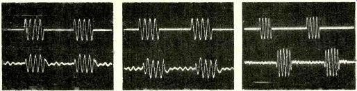
------ The excellent tone-burst response of the ADS 810 at frequencies of (left to right) 100, 1,000, and 7,000 Hz. The upper trace is the input signal.
Comment. As often happens, the sound of the ADS 810 could be predicted quite well from the general shape of its response curve. It has a slightly "distant" character, with strikingly clean, un-boomy bass and a crisp, detailed high end that compares very favor ably with the sound of some of the most highly regarded and sophisticated speaker de signs. Although there is no particular emphasis on any part of the spectrum, and the speaker's overall balance is outstanding, we felt that the clarity and definition of the high end was its most notable characteristic.
Our simulated "live-vs.-recorded" test confirmed this impression. These days, many speakers are surprisingly good in their ability to imitate our "live" sound source, but al most all of them seem to have some weak point-such as a heavy mid-bass, or a lack of extreme high-end response, or limited disper sion-that prevents them from simulating the original sound in a completely convincing manner.
The ADS 810 was one of the very few speakers we have tested in the past ten years or so that was so accurate that we could not distinguish its sound from the original in a side-by-side comparison. As we have pointed out on occasion, a speaker that has this ability will not necessarily suit every listener, since there are also personal taste (many people like coloration in their sound), individual room acoustics, and speaker performance below 200 Hz to be considered.
The apparent mid-range depression in the measured response of the ADS 810 is not audible as a defect of any sort, but rather as "an absence of presence" compared with the sound of many speakers that emphasize this region. Presence peaks may sell a lot of speakers in the showroom, but they tend to become tiresome in the home.
The bass coverage of the ADS 810 is certainly competent-but it may not satisfy pipe-organ and bass-drum buffs. For us, the smoothness and remarkable polar dispersion of the sound from the ADS 810 make it competitive with just about any other system we have heard, and much better than most.
+++++++++++++
Yamaha CR-620 AM/FM Stereo Receiver
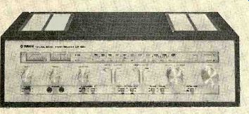
FROM their first appearance on the American market, Yamaha audio products have conveyed an image of outstanding quality, and for the most part they have been priced somewhat above competitive units. As a result, Yamaha is not a name one associates with a budget-price music system. However, the company has made a policy of maintaining a uniform performance-quality standard at all price levels, which is effectively illustrated by their current line of stereo receivers. For ex ample, from the high-price Model CR-2020 to the lowest-price Model CR-620, they all have a rated audio distortion of 0.05 percent from 20 to 20,000 Hz when delivering their rated power to 8-ohm loads.
The CR-620 we tested is rated at 35 watts per channel. It has an almost stark satin-
aluminum-finish front panel whose long dial cut-out is unadorned by any bezel or multi color illumination. Red LED's to the right of the dial scale serve as power and stereo FM indicators, and others to the left show whether the FM or AM tuner function is in use. Two large, legible meters to the left of the dial show FM center-channel tuning and SIGNAL Q (for "quality"). The Q reading combines relative signal strength and FM multipath distortion. Tuning a signal and orienting the antenna for a maximum meter reading with minimum needle fluctuation results in the best signal quality-hence the meter's name.
Below the meters are the bass and treble tone controls, each having eleven detented positions. Their center settings give a true flat frequency response, eliminating any need for a tone-control bypass switch. To their right is a LOUDNESS control of the same type that has been used with great effectiveness on previous Yamaha models. It, too, has eleven detented positions, with the clockwise limit being a flat position. One first sets the main vol ume control for the highest listening level one expects to use; thereafter, the desired listen ing level at any time is selected by turning the LOUDNESS knob counterclockwise from its flat position. As it is turned, the low and high frequencies are automatically cut to a lesser degree than the mid-range. This gives them an effective relative boost as the overall volume is varied through a maximum range of 20 dB.
Because Yamaha's loudness compensation is thus linked to the actual listening level, it is far more effective and less obtrusive than the type normally used.
At the right of the row of control knobs are the concentric VOLUME and BALANCE controls (the latter is a center-detented ring) and a tuning knob. In the center of the control panel are two bar-knob switches that give the Yamaha CR-620 a degree of flexibility rarely...
--------- FREQUENCY IN HZ (CYCLES PER SECOND)
... found in any receiver, let alone one of its price. The input selector is conventional, with positions for two tape decks, TUNER, PHONO, and AUX (another button on the panel selects either AM or FM when the tuner position is used). The other control, REC OUT SELECTOR, determines the program source that appears at the two sets of tape-recording outputs in the rear of the receiver. Its TUNER, PHONO, and AUX positions correspond to those of the input selector. The others are TAPE COPY 1-2 and TAPE COPY 2-1, for dubbing from either tape deck to the other.
The selection of programs for listening and tape recording is entirely independent.
Together with the dubbing facility, this lets the CR-620 serve as a tape-recording control center without disturbing one's normal listening habits. By selecting either TAPE 1 or TAPE 2 on the input selector, one can monitor from either tape deck while dubbing.
Across most of the panel width near its bottom is an inset area containing the remaining controls. These include pushbuttons for POW ER, SPEAKERS (separate output switches for two pairs of speakers) and both low and high filters (these have 12-dB-per-octave slopes), followed by the previously mentioned tuner selector, a STEREO/MONO MODE switch, and finally the FM MUTING switch. The latter is a dual-function control, converting the tuner to mono when the muting is disabled. There are also two stereo-headphone jacks on the panel.
On the rear panel of the CR-620 are screw-type binding posts for 75- and 300-ohm FM antennas and a wire AM antenna, as well as a hinged ferrite-rod AM antenna. The speaker terminals are insulated spring clips. One of the three a.c. outlets is switched.
The Yamaha CR-620 is furnished in an at tractive walnut-finish wooden cabinet. It is 20 inches wide, 6 1/2 inches high, and 15 1/2 inches deep; it weighs 25 pounds. Price: $330.
Laboratory Measurements. We measured the performance of the CR-620 in our usual manner, in general accord with the IHF test standards. The one-hour preconditioning at one-third power left the top of the cabinet over the output transistors only moderately warm. The power output at 1,000 Hz with both channels at the clipping level driving 8-ohm loads was 45.6 watts, and the 4- and 16-ohm outputs were 55.5 and 31.1 watts.
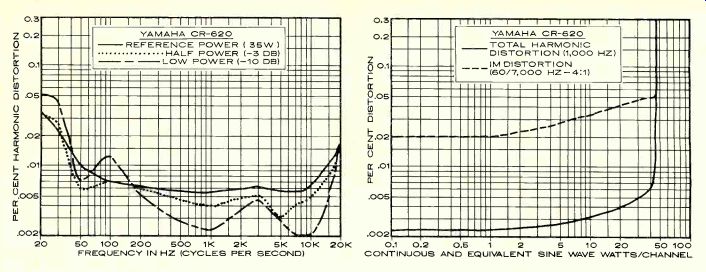
The THD at 1,000 Hz was indeed extraordinarily low for an amplifier of any price. It measured about 0.0025 percent (the test equipment residual-distortion level) from 0.1 watt to several watts output, reaching 0.005 percent at 30 watts and 0.006 percent at 40 watts. The IM distortion was generally somewhat higher, measuring 0.02 percent up to about 1 watt and 0.05 percent at 40 watts.
At the rated 35 watts per channel, the distortion was about 0.05 percent (as rated) at 20 Hz, dropping to 0.01 percent at 50 Hz and 0.006 percent across most of the audio range.
It rose slightly at high frequencies, to 0.015 percent at 20,000 Hz. At half power and one-tenth power, the distortion characteristics were similar, with somewhat lower distortion levels (at 3.5 watts output, the distortion was under 0.005 percent from 200 to 15,000 Hz).
The AUX input sensitivity was 61 millivolts for 10 watts output, with a very low-82-dB unweighted noise level. The PHONO sensitivity was 1 millivolt, and its noise level was also lower than average, -75.5 dB. Phono over load occurred at a very safe 145-millivolt in put at 1,000 Hz.
The tone-control curves were hinged at about 400 Hz for the bass and 2,500 Hz for the treble. The first three steps from center gave only a slight response change, but at maximum settings the boost or cut was more than adequate. With the controls centered, the response was flat within ±0.5 dB from 20 to 20,000 Hz.
The HIGH FILTER response was down 3 dB at 8,000 Hz and the LOW FILTER cut the response by 3 dB at 27 Hz. The loudness con tours were very mild near maximum volume (as set by the loudness control), but boosted both lows and highs quite markedly at the lowest settings. The RIAA phono equalization was within ±0.5 dB over the extended range of 20 to 20,000 Hz. Measured through the inductance of a phono cartridge, it showed a slight high-frequency rise beginning at about 1,000 Hz, reaching a maximum of about +1.2 dB between 10,000 and 13,000 Hz before falling to-0.8 dB at 20,000 Hz.
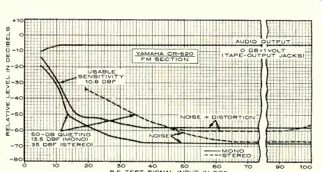
The FM-tuner section of the CR-620 had an IHF sensitivity in mono of 10.8 dBf, or 1.9 microvolts (RV). The stereo sensitivity was set by the switching threshold of about 19 dBf (5 RV). The more important 50-dB quieting sensitivity was 13.5 dBf (2.5 pN) in mono and 35 dBf (30 µV) in stereo. The low tuner distortion of 0.13 percent in mono, 0.1 percent in stereo seems to confirm that a high level of performance is also carried through the tuner sections of the Yamaha receiver line. The signal-to-noise ratio was 68 dB in mono and 67 dB in stereo. Stereo distortion at 65 dBf (1,000 RV) with L-R modulation was 0.56 percent at 100 Hz, 0.14 percent at 1,000 Hz, and 0.032 percent at 6,000 Hz. The only measurement made on the AM tuner section was of its frequency response, which was quite restrict ed: down 6 dB at 45 and 2,000 Hz.
------- YAMAHA CR-620 FM SECTION
The stereo performance of the CR-620 FM tuner section was also excellent. The frequency response was within 0.5 dB from 30 Hz to beyond 10,000 Hz, falling to -2.4 dB at 15,000 Hz. The channel separation was be tween 35 and 45 dB from 70 to 10,000 Hz, de creasing to 30 dB at 30 Hz and 25 dB at 15,000 Hz.
The capture ratio was 1.5 dB at 45 dBf (100 uV) and 1 dB at 65 dBf input. AM rejection was 70 dB. Image rejection was only fair at 50 dB, but the alternate-channel selectivity of 73 dB was very good. Adjacent-channel selectivity was 5 dB. The muting and stereo thresh olds were, respectively, 20 and 24 dBf. In spite of the effect of the multiplex filter on the 15,000-Hz response, the 19-kHz pilot carrier in the audio outputs was suppressed to only -56 dB. The tuner hum was -67 dB.
Comment. Looking at the overall performance of the Yamaha CR-620, it is easy to see where Yamaha engineers have decided to carry a given level of performance through their product line. Aside from its power output, the audio amplifier of this receiver would rank with some of the most sophisticated designs we have seen. Even its transient capabilities are well beyond what one would expect to find in its price class, with a 1.5-microsecond rise time and a 15-volt-per-microsecond slew rate. The latter represents very respectable performance indeed for an amplifier of this power, to say nothing of one that is part of a $330 receiver.
The tuner is also first-rate with respect to the important factors of noise, distortion, and separation. Moderate sacrifices have been made in such areas as sensitivity, image rejection, capture ratio, and pilot-carrier suppression, although all of these parameters are at least adequate.
In its mechanical construction and general "feel," the CR-620 is Yamaha through and through. We had the opportunity to use it side by side with the top-price Yamaha CR-2020, and we can attest to their essential similarity.
The SIGNAL Q meter worked well. It is per haps not quite as sensitive an indicator of multipath distortion as the best of the specialized multipath meters, but it is certainly far better than most, and its combination with a signal-strength reading merits high praise for convenience (although the meter saturated at 1,000 uV, which gave a reading of 90 on the scale of 100).
When we first received the Yamaha CR-620, its price had not yet been fixed. From its features and specifications, we guessed that it would sell for $400 to $450. When we learned that the price was about $100 less, we were, to put it mildly, surprised. It brings a superior quality of performance and styling, plus novel and useful control versatility, to the budget-price range. Altogether, we judge the CR-620 to be one of the better values in stereo receivers.
+++++++++++++
Sankyo STD-2000
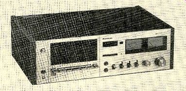
THE Sankyo STD-2000 is a full-feature moderate-price cassette deck whose performance matches its impressive array of operating conveniences. The STD-2000 is a front-
loading recorder with an automatic tape-loading system similar to those of some other Japanese cassette machines. In addition to the Dolby noise-reduction circuits found in any high-fidelity cassette deck, it has separate three-position bias and equalization switches that make it compatible with almost any type of tape.
The cassette compartment, at the left of the front panel, is normally covered by a clear plastic door, below which is a row of piano-key operating levers. Pressing the EJECT lever causes the door to withdraw into the body of the machine and a cassette loading platform to appear, angled slightly upward to the rear, at the front of the compartment. When the cassette is placed on the platform, it moves up into the machine automatically, dropping the cassette into its playing position. The angle of the cassette, the front lighting, and the contrasting-color background make it easy to see how much tape is on the hubs at any one time.
The control keys perform the usual functions, and they can be operated in any sequence without going through STOP (although the tape must be halted before the RECORD key can be engaged). Whenever the EJECT key is pressed (even when the tape is in motion), the door flies open and the cassette is moved forward to where it can be grasped.
To the left of the cassette compartment are the pushbutton power switch and a head phone jack. To its right are the index counter (which has a memory feature that stops the tape automatically in rewind when the counter returns to a 999 reading) and two micro phone jacks. Small lights in a row in the center of the panel glow to show that the tape is in motion and whether it is at normal speed or in one of its fast-winding modes. A red RE CORD and a green DOLBY light are nearby.
At the lower center of the panel is a row of four lever switches. One switches the recording inputs between LINE and mic (or DIN) sources; the different sources cannot be mixed. The three-position DOLBY switch turns the Dolby system on when it is moved either up or down. In the up (MPx) position, it also inserts a low-pass filter in the recording amplifier to prevent interaction with a tuner's pilot-carrier leakage when recording FM.
The next two switches, BIAS and EQ, are tape-type selectors. They each have settings marked NORM, CrO2, and FeCr, and they are normally set to the same point for a given tape. However, the separation of the functions does give the user some added flexibility. The EQ switch adjusts both recording and playback equalization, using the 120-microsecond characteristic for normal tape (ferric) and 70 microseconds for the others.
Continuing to the right, the next control is a small OUTPUT LEVEL knob, which adjusts the playback level ahead of the meters. To its right are concentric RECORD LEVEL knobs. At the upper right of the panel are two large, well-lit meters, calibrated with the standard Dolby level at their +3-dB marks. Between them is a red LED PEAK light that flashes at +3 dB. Phono-jack inputs and outputs and a DIN socket are in the rear of the recorder.
The Sankyo STD-2000, including its standard simulated-walnut-veneer wooden side panels, is about 18 inches wide, 5 1/2 inches high, and 11.5 inches deep. It weighs 18.3 pounds. Price: $299.95.
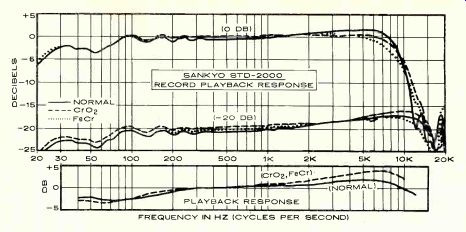
Laboratory Measurements. The instruction manual does not recommend specific tapes to be used with the STD-2000, or even suggest bias and EQ settings for popular tapes. There fore, we measured record-playback frequency response with a number of tapes, looking for the ones that gave the flattest and widest response with our particular machine.
Eventually, we chose Maxell UD-XL I for the normal tape, Sony CrO2, and Sony FeCr (Scotch Classic was slightly flatter in the FeCr category, but since it has been superseded by Scotch Master III, we did not base our measurements on it).
The UD-XL I response was within ± 1.5 dB from 25 to 14,000 Hz. Scotch Master (not the current version) and Memorex MRX2 were nearly the same, with the high end rolling off above 12,500 Hz. TDK AD gave a slightly rising high-end response, varying ±3.5 dB from 25 to 16,500 Hz.
With CrO2 settings, Sony CrO2 tape gave a response within ±2 dB from 25 to 14,500 Hz.
BASF Chromdioxid Super had a "hotter" top end; it was ±4 dB from 25 to 16,500 Hz. A popular "chrome-equivalent" tape, TDK SA, also had a rising high end; it was ±4 dB from 25 to 15,000 Hz. The similar Maxell UD-XL II showed a drop at the extreme high end in this machine. Sony FeCr had a slightly rising top end and was within ±3 dB from 25 to 15,500 Hz. Scotch Classic was extremely flat to 10,000 Hz, dropping off at higher frequencies to-5 dB at 15,000 Hz.
The Dolby system tracked within 2 dB (the change in response with Dolby in or out) at all frequencies at levels of-20,-30, and-40 dB, which meets Dolby specifications. The MPX filter began to take effect above 10,000 Hz. The playback frequency response was measured with some of the new TDK "AC" series of test tapes. It was within ±2.5 dB from 40 to 12,500 Hz with the TDK AC-337 test tape. The 70-microsecond equalization was measured with a Teac 116SP tape, giving an upward-sloping response of ±3.5 dB from 40 to 10,000 Hz.
For a 0-dB meter reading, the line input at maximum gain was only 25 millivolts, and through the mic input the sensitivity was 0.29 millivolt. The microphone input overloaded at a fairly safe 56 millivolts. The playback out put level from a 0-dB recording varied from 0.42 volt with FeCr tape to 0.46 volt with UD XL I tape.
The playback distortion (third harmonic of a 1,000-Hz signal) at a 0-dB recording level was 0.5 percent with UD-XL I, 1 percent with CrO2, and 1.3 percent with FeCr. The respective 3 percent distortion levels were reached with recording inputs of +9.5, +5, and +5 dB. The unweighted signal-to-noise (S/N) measurements, referred to the 3 percent distortion level, were 55.5 dB with UD XL I, 52.2 dB with Sony CrO2, and 51.3 dB with Sony FeCr. With IEC "A" weighting, these measurements improved to 61, 57.4, and 57 dB, respectively. With CCIR weighting, and using the Dolby system, the respective S/N readings were 66.5, 63.6, and 63.3 dB. The noise increase through the micro phone inputs, even at maximum gain, was a negligible 2 dB.
The wow and flutter in a combined record/playback measurement was 0.08 percent (un-weighted rms). In fast forward or rewind, the recorder moved a C-60 cassette from end to end in about 82 seconds. The meters were slightly underdamped, with an overshoot of about 20 percent on 0.3-second tone bursts.
They were accurately calibrated in terms of standard recording levels, with the Dolby level of 200-nW/m reading +3 dB and the 250 nW/m reference of the TDK tapes reading +5 dB. The PEAK light began to glow at +3 dB.
The headphone volume was excellent, even with 200-ohm phones, which often cannot be driven to usable volume levels by the head phone outputs of tape recorders.
Comment. The sound of the Sankyo STD-2000, either on tapes recorded with it or using high-quality prerecorded tapes, was excellent, which is not surprising in view of its measurements. The "acid test"-recording FM-tuner interstation hiss at a-10-dB level and comparing the playback to the incoming signal-completely confirmed our test results and listening impressions. The input and out put sounds were indistinguishable with Maxell UD-XL I and NORM settings or with Sony CrO2 and using CrO2 settings. Only a slight emphasis of extreme highs kept the TDK tapes and the Sony FeCr from doing as well.
The auto-load feature is convenient and works well, but it does take a little getting used to. In particular, when a cassette is ejected, one must be careful to grip its edge firmly for withdrawal. Even a slight inward pressure on the cassette will cause the ma chine to draw it back in, ready for operation.
When all aspects of the performance of the Sankyo STD-2000 are considered, it is clear that this is an above-average machine selling at an average price. Perhaps one can obtain more impressive measurements on some more expensive machines, but this one is the audible equal of any of them, at least when re cording from FM or discs. We did not try any "live" recording, but, noting the extremely low noise level of the microphone amplifiers, we suspect that it would do a fine job, especially with low-output microphones that could not overload its inputs.
We also found, as we have with some other recorders, that the best overall S/N performance is obtained with a good grade of ferric-oxide tape. Chromium dioxide and ferri-chrome may have slightly extended high-frequency response and slightly more headroom, but they distort at a lower level and thus do not have quite as great a margin between the overload point and the background noise.
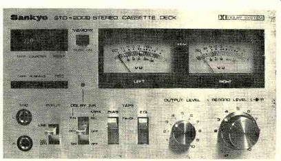
----------------- A partial view of the Sankyo STD-2000's front panel shows its level controls and meters as well as operating controls for bias and equalization and the Dolby system.
-------- FREQUENCY IN HZ (CYCLES PER SECOND)
+++++++++++++++++++++
dbx 128 Dynamic-range Enhancer/Noise-reduction System
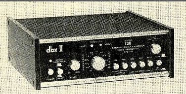
IN only a few years, dbx has earned itself a name as "the other" noise-reduction sys tem. One difference between Dolby and dbx is that, while a Dolby-B encoded program can be listened to without decoding (if you are willing to accept a slight added brightness), all dbx-encoded programs (as with the professional Dolby-A system) are quite unlistenable unless properly decoded. As might be expect ed, the two systems are completely incompatible with each other.
The new dbx Model 128 is a highly versatile tool for enhancing the dynamic properties of any program material, and its usefulness is certainly not confined to tape-recorder noise reduction. It has two completely separate functions that can be used individually or together, as desired.
The dynamic-range enhancement effect of the dbx 128 is accomplished by its adjustable compressor/expander, which is much like that of previous dbx units. With a single front-panel control knob, its input/output relation ship can be varied from "infinite" compression, or full limiting, to normal linear operation, to an expansion mode with a slope as great as 2.0. This means that a 10-dB increase in the signal-input level will produce a 20-dB increase in the output. Conversely, a 2.0 compression slope will give an output-level change of only 5 dB for each 10 dB of input-level change. At the center (1.0) setting, the device has no effect on the input/output transfer characteristic.
The compressor/expander can be used in two modes: "linear" operation over the full dynamic range of the program, and "thresh old" operation only when the input level exceeds a preset threshold (set by a knob on the panel of the dbx 128). In the latter mode, red and amber LED's above the slope control show whether the signal is above or below the threshold level. The lights also glow in the linear mode, but the setting of the threshold control has little effect except to vary the average program level from the unit.
Linear expansion can be used to restore some of the dynamics to a program that has been compressed, and it is also an effective noise-reduction technique. When the program is expanded, the gain of the device drops appreciably during quiet passages, thus attenuating or even removing hiss and hum.
Compression is useful for processing music that is to be used as background, or for play back in an automobile or other noisy environment. Another practical application is as an automatic level control when recording a number of voices having different levels. In its threshold mode, the expander serves as a "peak un-limiter" that is especially valuable for processing FM broadcasts whose peaks are limited at the transmitter.
The second basic function of the dbx 128 is to reduce noise in tape recording (more accurately, to prevent noise from being added by the tape-recording process). This is essentially the function of the Dolby system as well, but the two work very differently. The Dolby system affects only the higher frequencies (above 500 or 1,000 Hz), and operates only on low signal levels. The dbx, on the other hand, compresses the signal with a 2.0 slope before it enters the recorder. The compression takes place at all signal levels and over the full frequency range. In playback a complementary expansion takes place, restoring linearity while dramatically reducing any noise that might have been added in the record-playback process. Instead of Dolby's maximum noise reduction of about 10 dB, the dbx system pro vides some 30 dB of noise reduction, and it does not require any critical input-level matching.
The very magnitude of the dbx noise reduction is both its strongest and weakest point.
Its total subjective effectiveness is far greater than that of any other consumer noise-reduction system. Unfortunately, a dbx-processed signal is not listenable in its "raw" state (it sounds very shrill and compressed). To be useful, it must be expanded in the correct manner.
The compression/expansion process is not quite so simple as has been described. Internal pre-emphasis circuits in both the signal and control paths give the signal leaving the dbx 128 (to the recorder) a low-frequency boost, a mid-high-frequency dip, and a rising response at the highest audio frequencies.
The opposite response is applied to the playback signal from the recorder, resulting in a flat overall response. The dbx system em ploys a proprietary rms-level detector to operate the signal-processing circuits. Therefore, playing back a dbx-encoded program through any other expander, even if it has the correct slope, cannot produce the correct results (unless it also has the same type of detector and the same frequency-response shaping). The dbx 128 is especially convenient to use as a tape-recorder noise reducer, since 2.0 compression and expansion slopes are set internally when the REC or PLAY buttons are pressed (the earlier dbx devices required that the slope control be set to the correct value for each phase of the recording and playback process). Only a single pair of processing channels is available, so the unit must be switched manually between REC and PLAY modes and one cannot monitor the program from the tape while it is being made. The de coding circuits of the dbx 128 can also be used to process the playback from a dbx-encoded LP record, only a very few of which are avail able at present.
The dbx 128 is identified on its panel as the "dbx II." Although similar in principle to the original dbx (which was, and is, used in professional applications), the dbx II has been modified slightly to meet the special needs of home high-fidelity systems. It has low- and high-frequency filtering to remove the effect on the rms-sensing circuits of turntable rumble and high-frequency response aberrations in the tape deck. Because of the detail differences between them, tapes made with one of the two dbx systems cannot be properly de coded by the other.
Most of the operation of the dbx 128 is con trolled by six pushbuttons. Three are for the noise-reduction system and are marked REC, BYP, and PLAY. In the BYP condition, the noise-reduction circuits are completely by passed. Another button selects TAPE or DISC operation. This connects the dbx processing circuits either to the playback output of a tape recorder or to the tape-recording output of the amplifier. In the latter case the signal processing affects any program selected within the amplifier. Although this can be a dbx-encoded disc, it can as easily be an FM program or any other source.
The dynamic-range enhancer is controlled by two buttons marked PRE and POST. In the TAPE mode, these buttons place the enhancer circuits in the signal path either just before the tape deck or in its playback output (in the dbx Disc mode, these buttons have no effect).
The former gives the dbx 128 its unique ability to improve the sound of the original program by increasing its dynamic range and reducing its noise level before it is recorded. (Since the dbx circuit adds some 30 db to the dynamic range of a tape recorder, it is perfectly feasible to expand the range of a signal before re cording it, without exceeding the range of the recorder or adding noise during the recording and playback process.) In addition to the controls already mentioned, the front panel has a pushbutton power switch with LED pilot and a PLAY LEVEL MATCH knob that matches the playback level from a dbx-processed tape with that of a non-
encoded tape played in the BYP mode.
The dbx 128 is meant to be connected in the tape-monitor path of an amplifier or receiver.
On its back panel, there are input and output jacks for connecting a tape recorder. A QUAD COUPLER jack interconnects two dbx 128 units for quadraphonic operation, so that their expansion and compression characteristics "track" to prevent wandering of apparent sound positions.
The dbx 128 is 11 inches wide, 10 3/4 inches deep, and 344 inches high, weighs 8 pounds, and consumes only 10 watts from the power line. Price: $450.
dbx 128 . . .
Laboratory Measurements. Conventional measurements on a dynamic signal processor such as the dbx 128 would be valueless, and in any case there are no comparable products against which to make a comparison through such measurements. We did verify that the in put/output slopes followed the markings on the panel and that the recording and playback frequency responses were as represented, accurately complementing each other. The specifications of the dbx 128 show that it is compatible with virtually any type of amplifier or recorder (of course, the amplifier must have a tape-monitoring path or access to the preamp outputs and power-amplifier inputs). The dbx 128 will not add any detectable noise or distortion to a program. Beyond these determinations, it is clear that the performance of the dbx 128 can be judged only in actual use.
Comment. The noise reduction afforded by the dbx 128 with a moderate expansion slope was very worthwhile. The slope control must be set with care while one listens for un natural sound qualities, and it should then be backed off until they disappear. As the control is advanced clockwise, the background noise drops off and soon disappears. Unfortunately, there is an inevitable modulation-noise effect that can cause a "fuzz" of noise to appear on transient sounds, such as those made by a piano or other solo instrument recorded against a quiet background (which becomes dead silence when heard through the dbx 128). The instruction manual explains the effect, which it claims is audible only because the background noise with dbx is so much lower than with any other noise-reduction system. Be that as it may, the cure is simple use less expansion. Settings beyond 1.4 are never needed, and usually 1.2 or 1.3 is sufficient. A 1.3 expansion means that a 40-dB program's dynamic range is increased to more than 50 dB. The extra 10 dB means that one should be careful not to mate a powerful amplifier with speakers that cannot handle its output. And also bear in mind that an under powered amplifier may be driven into clipping by the expanded signal.
As a recording-noise reducer, the dbx 128 can virtually overcome the chief limitation of the cassette medium-its tendency to saturate at high levels and lose its high-frequency response. Many recorders, although measuring flat at-20 dB, have little response above 10,000 Hz when the signal level is 0 dB. This is largely responsible for the dulling of high-frequency transient sounds in cassette recordings and their general lack of "open ness" compared with open-reel tape.
One obvious solution is to record at lower levels, such as-20 dB. Unfortunately, tape hiss makes that impracticable-or it did until dbx came on the scene. With the added 30 dB of dynamic range provided by dbx, it be comes perfectly feasible to record at-20 dB, barely moving the recorder's meters, and yet have a hiss level in playback that is at least as low as the recorder's normal signal-to-noise ratio with Dolby or ANRS (the latter processes should not be used simultaneously with dbx, as they would serve no purpose).
Can the dbx system be heard in operation? Generally not, although this may depend on the specific program material. After hours of use, we could never be certain that we heard any unnatural effects produced by the dbx noise-reduction system. If there were any anomalies introduced by the process, they were far less objectionable than the noise or tape-saturation effects that had been eliminated. The two-step noise reduction must not be confused with the dynamic-range enhancement mode, which definitely can be heard when used to excess; success with it requires a light touch on the part of the user. With an open-reel machine, the dbx 128 allows a re cording to be made at almost any level, with literally no audible noise being added.
Although the dbx 128 can, in a sense, make a silk purse out of a sow's ear, its cost makes it an unlikely choice for that role. Used with a really good cassette recorder, how ever, it may change a few minds about the limitations of cassettes. Also, if (like us) you find the faint hiss remaining in the background of many stereo FM transmissions annoying, this device will get rid of it completely and will usually enhance the program's sonic quality in the process.
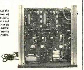
--- Top view of the chassis of the dbx 128 gives an indication of
the complexity of the circuitry.
The versatile 128 can be used as a full compander or as an after-the-fact expander.
Note the extensive use of integrated circuits.
====================
Also see:
Turntables -- What Are Your Options (Jan. 1985)
Source: Stereo Review (USA magazine)