THE PHONO CARTRIDGE--A piece of technological wizardry we perhaps take too much for granted. (Feb. 1979).
To understand its operating principles is to appreciate the level of technological wizardry that produced it.
By William Curtiss
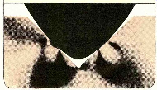
----These simulations of record-groove stress patterns show a conventional elliptical stylus (above) making contact in two fairly small areas, producing narrow, extended stress patterns.
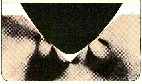
-----A Shibata stylus (above) has an elongated contact area, which theoretically distributes the stylus force over more of the groove wall, reducing the pressure, as the broadened, patterns show.
AMONG the more persistent popular myths is the one stating that, according to scientific theory, the bumblebee cannot fly. But, unaware of the aerodynamic theories involved, the insect, in his ignorance, manages to buzz about his business quite well. By the same token, the phonograph record can be seen, on the face of it, to be such a practical impossibility that if it hadn't yet been invented, it probably wouldn't. be. A superficial analysis of the engineering problems involved would likely find it impossible (1) to convert sound waves into microscopic undulations in soft plastic material or (2) to subsequently "read" these undulations with an equally microscopic stylus so as to re produce the original sound wave. The question would inevitably arise as to whether there weren't an easier way to store and reproduce sound, and it is more than a little likely that the phonograph record would be dismissed as a Rube Goldberg device of interest only to technical ignoramuses such as Thomas Edison and Emile Berliner.
Fortunately for us, these seat-of-the-pants inventors made the impractical practical simply by going ahead and doing it rather than worrying about whether it could be done. And it is rather heartwarming to remember that Edison himself was astonished when his crude tin-foil-coated cylinder device worked the very first time he tried it.
Early phonograph cylinders and discs were hardly "high fidelity," de spite the enthusiastic testimonials in advertisements of the time that their sound couldn't be distinguished from the original. Yet, they did bring music reproduction to the homes of the day, and it was certainly better than nothing. As we all know, the phonograph shortly became immensely popular and the arduous job of refining the concept and improving the quality began; it continues to this day.
The Stylus
If you know anything about the task that confronts a phono stylus, you might agree with the theoreticians that it lies somewhere between the impractical and the impossible. In order to follow the undulations of the record groove, especially toward the center of the disc where wavelengths become microscopic (the groove-wall modulation produced by a 15,000-Hz tone is about half a thousandth of an inch), the stylus tip doing the tracing must be tiny. The task is complicated by the difference between the shape of the original cutting stylus and that of the playback stylus. To cut the master disc cleanly and quietly, the cutting stylus must have a knife-like edge: it is shaped somewhat like a triangular chisel with facets on the edges to burnish the groove as it goes along. The play back stylus, however, must be rounded at the edges or it too will "cut" the disc. Unfortunately, rounded surfaces cannot follow precisely a path chiseled out by a triangular-shaped cutting instrument. The resultant inaccuracy is called tracing distortion, and it worsens as signal wavelengths get shorter.
The first experimental step toward reducing tracing distortion was the use of a smaller tip on the playback stylus.
Unfortunately, as the stylus gets smaller, the pressure (force per unit area) exerted on the groove walls by its tracking force increases, and record wear becomes a real risk. The smallest practical diameter for a ball-type ("spherical") stylus tip is about 0.0005 inch-approximately the same dimension as the wavelength of a 15,000-Hz tone in the inner grooves of a record.
"...the elliptical stylus was greeted with dire predictions of economic impracticality. Now, ten years later, all but the least expensive cartridges have elliptical styli."
Such a stylus will have difficulty playing some records since a 0.0005-inch (5-mil) spherical tip will ride low or even on the bottom of the groove (which is 0.001 inch or more wide) where it is likely to pick up more noise than signal.
For this reason, the biradial or "elliptical" stylus was developed.
As its name implies, the biradial stylus has two different radii of curvature.
It has a sharp curve where it contacts and "scans" the walls of the groove, but its width is such as to keep the stylus riding on the groove wall at an appropriate distance from the groove bottom. A typical elliptical stylus might have a scanning radius of 0.0002 inch and a supporting width of 0.0007 inch.
It will trace short wavelengths with lower distortion than a 0.0005-inch spherical tip and support itself in a better position in the groove while doing so. The advent of the elliptical stylus was greeted with a mixture of enthusiasm and dire predictions of economic impracticality. Now, ten years later, all but the least expensive hi-fi cartridges have elliptical styli.
The introduction of CD-4 quadraphonic discs was made possible by the development of styli capable of tracing the extremely short wavelength of a 40-kHz signal. The "Shibata" stylus had a new and more complex geometry, and it engendered numerous offspring--the "Quadrahedron," "Stereohedron," "Hyperbolic," "Pramanik," and others. They are all similar to the extent that they are ground with yet a third radius: the curvature running from the very point of the tip and up along the stylus' sides to its top. This curvature defines the vertical length over which the sides of the stylus contact the groove walls. A longer vertical contact need not impair the effective "sharp ness" of the stylus for tracing groove detail, but it will increase the overall contact area, thus reducing stylus pressure and consequent record wear. In fact, according to the Shibata theory, you can make the edge of the stylus even sharper than it is in the elliptical configuration-and still incur no penalty in stylus pressure if the vertical con tact is made long enough. Although these complex (and still expensive) styli are certainly not required for adequate reproduction with ordinary stereo records, they can noticeably improve tracing.
While stylus geometry plays the major role in establishing the short-wavelength tracing ability of a cartridge, stylus mass ultimately establishes the high-frequency response of the system. The faster the stylus must reverse direction-that is, the higher the recorded frequency-the greater the force required to accelerate its mass. If this acceleration is to be accomplished without tearing up the vinyl, the effective stylus mass must be extremely small. And stylus mass has a further effect on high-frequency response. Vinyl has a certain amount of springiness; it is compliant, deforming and then springing back under the force exerted on it by the stylus. This compliance resonates with the effective mass of the stylus at some (usually high) frequency, just as any weight-and-spring system resonates. The resonant frequency of vibration of the stylus/vinyl groove combination essentially determines the highest frequency to which the stylus can mechanically respond with accuracy. This can vary from per haps 12,000 Hz in an inexpensive high-mass stylus assembly to more than double or triple that frequency with a quality stereo or CD-4 cartridge. And the vinyl material's compliance, which will vary from record to record, also has its influence.
"Not all cartridges receive the electrical loading for which they're designed, and performance may consequently vary as much as 7 or 8 dB ... "
Several factors combine to determine the effective tip mass of the stylus: the mass of the diamond itself (and its mount), the mass of the shank or cantilever (and how that mass is distributed), and the mass of the moving element (the magnet, coil, piece of iron, or whatever) that generates the electrical signal. You can't just weigh a stylus to determine its effective mass, because the figure must take into ac count not only the individual mass elements, but also where they are located in relation to the pivot. A relatively great mass near the pivot may contribute less to the total effective mass than a smaller one far from the pivot.
Being farthest from the pivot, the diamond and its mount contribute most to the effective mass. Next in importance is the shank or cantilever, especially at the far end near the stylus.
Some manufacturers therefore use tapered cantilevers to provide less mass without loss of rigidity, or they fashion shanks from exotic materials such as beryllium or carbon fiber. Some have used extremely thin-walled aluminum with miniature internal reinforcing rods of beryllium, and some have used telescoped shanks.
Transduction System
Once the vibrations from the groove have been conveyed into the cartridge body via the stylus and cantilever, they must be converted or transduced into electrical signals. A variety of means can be used to accomplish this, al though some form of magnetic transduction is by far the most common.
To consider other means first, the stylus can be coupled to a piezoelectric element-a substance such as barium titanate that generates a voltage across itself when twisted or strained. The resulting cartridge, called a "crystal" or "ceramic" type, produces a relatively high output voltage but is not likely to be of high-fidelity quality. However, miniature strain-gauge and electret elements have been used successfully as high-fidelity transducers. The strain gauge requires an external d.c. power supply, the current flow from which is modulated by imbalances in the strain gauge bridge that are caused by the stylus motion. The electret cartridges are roughly similar in operating principle to an electret microphone, and they re quire a passive or active internal circuit to buffer and otherwise process their output signals before they can be routed to the preamplifier.
Magnetic cartridges come in three basic configurations: moving-magnet, moving -iron, and moving-coil. Explained as simply as possible, both the moving-magnet and moving-iron types employ fixed coils of wire within the cartridge body and a voltage is generated within the coils whenever the magnetic flux passing through them varies.
In a moving-magnet cartridge, the magnetic field is supplied by a tiny magnet attached to the rear of the stylus shank.
As the stylus shank vibrates, the magnetic field impinging on the coils varies and an electrical signal is induced. In a moving-iron (sometimes called a variable-reluctance) cartridge, a small piece of iron alloy is attached to the stylus shank. It is not a magnet itself, but it varies or modulates the field (supplied by a fixed internal magnet) that impinges on the coils. These modulations generate the voltage in the coil. A variation on this theme is the induced-magnet cartridge, in which the magnetic flux of a fixed magnet is induced in an iron sleeve on the cantilever. The sleeve then operates as a moving mag net. There are numerous other variations on these principles employing several fixed and/or moving magnets and different coil arrangements. Al most all have user-replaceable styli.
Most of these "fixed-coil" types generate a comparatively high level of audio electrical signal-typically 3 to 5 millivolts at 1,000 Hz for a laterally recorded level of 5 centimeters per second. However, the cartridge's output voltage varies with frequency and thus must be equalized--a job competently taken care of by the RIAA circuits in the phono-input section of your amplifier or receiver. Both types have relatively high output impedances and require proper "loading" from the phono-preamp section of your amplifier or receiver to function at their best. This is of sufficient importance to warrant an explanation.
As mentioned previously, the stylus assembly physically resonates with the vinyl groove walls at some relatively high frequency (beyond that frequency the output of the cartridge diminishes rapidly). At the resonance frequency there is likely to be a peak in the frequency-response curve. The amplitude of the peak, and the frequency range over which it occurs, is determined by the mechanical damping of the stylus.
This damping is provided mostly by the carefully controlled characteristics of the elastomeric bearing (the pivot) that supports the stylus assembly. No doubt it would be possible to design a stylus so that it would be critically damped inherently, and there would then be no peak in the output of the cartridge at resonance. However, to do so would require a substantial amount of internal damping, and the resultant friction would impede stylus motion and re quire additional tracking force. A less problematic approach-used in virtually all fixed-coil cartridge designs-is to make use of an electrical resonant circuit to compensate for the mechanical resonance and thus flatten out the response curve. This electrical circuit involves both (1) the inductance and resistance of the coils within the cartridge and (2) the load resistance and capacitance to which the cartridge is connected. The load resistance is determined by the input circuit of the preamplifier; the capacitance is that of the tone-arm wiring, the connecting cable to the preamplifier, and the preamp's own input capacitance.
It is pretty much standard practice to design magnetic cartridges of this type for termination with a 47,000-ohm resistive load, and preamplifiers are de signed to supply it. (CD-4 cartridges are designed for a 100,000-ohm load, a value provided by the CD-4 demodulator to which they are connected.) But the optimum load capacitance is not standardized, and cartridges range in their requirements from 150 to 450 picofarads. Furthermore, not all preamplifiers are designed in such a way that their input circuitry provides a pure resistance and capacitance, which means that the load they present to the cartridge can be somewhat in doubt. Not all cartridges receive the electrical loading for which they're designed, and their mid- and high-frequency performance may consequently vary as much as 7 or 8 dB from flat response.
As a word of practical advice, if you know the recommended load capacitance for the cartridge (it's generally given in the owner's manual) and the input capacitance of the preamplifier (it will be appearing more frequently in specification sheets), the difference between the two can be made up with the capacitance of the tone-arm wiring and that of the interconnecting cables. Alternatively, a fixed capacitor purchased from an electronics store can be wired across the phono input to achieve the total recommended value. Record player manufacturers are beginning to print data on the capacitance contributed by their products. If not provided in the player's instruction manual, this vital piece of information can be obtained at the cost of a letter or phone call to the manufacturer.
-------
PHONOGRAPH CARTRIDGES: A REPRESENTATIVE SAMPLING
CARTRIDGE SPECIFICATIONS
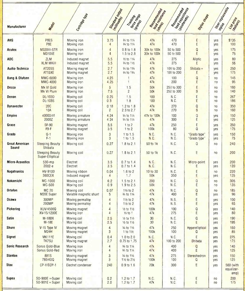
THE chart lists several models at or near the top of the lines of the major cartridge manufacturers, together with some of their mom important specifications, Information on frequency response and channel separation has been omitted because the use of different test records by different manufacturers invalidates comparisons.
Of the specifications indicated, standard output is referred to a recorded lateral velocity of 5 centimeters per second at 1,000 Hz. Tracking-force range will give a rough idea of the tracking abilities of the various cartridges, although it is by no means an absolute indication of merit.
The importance of load resistance and capacitance is explained in the text. The symbol "S" represents a spherical stylus, "E" an elliptical stylus, and "0" a stylus that is specially shaped for CD-4 four-channel reproduction but will also serve well in conventional use. When a certain stylus shape clearly does not fit into any of these categories, the manufacturer's nomenclature is used. N.C. = not critical; N.S.= not supplied.
The "Cartridge type" column indicates the internal electromechanical format of the cartridge; however, because of design and nomenclature variations the designations should not be viewed as anything other than approximate descriptions of operating principles, nor as any indication of quality or design superiority.
--------------
"Specifications are useful only in a comparative sense, and then only when the cartridges in question have been tested under identical conditions."
-------------------
The other type of magnetic cartridge, the moving-coil, has a reputation for high-frequency definition and clarity superior to that of the fixed-coil cartridges-a reputation that persists al though scientific support for it has yet to emerge. In a moving-coil cartridge the stylus is attached to miniature coils of wire that are immersed in a fixed magnetic field within the cartridge. The signal voltage is generated by the movement of the coils through the field. Obviously, only a very few turns of wire can be used in the coils if the effective mass at the stylus is not to be come excessive. Accordingly, the signal-voltage output of these cartridges is very low, and an accessory transformer or a pre -preamplifier (frequently called a "head amp") is usually required between the cartridge and the normal phono input. (There are a few "high -output" moving-coil cartridges on the market that can feed standard -gain phono inputs directly, but even these have outputs significantly lower than that of the typical fixed-coil cartridge.) With a few exceptions, the stylus assemblies of moving-coil cartridges cannot be changed by the user; the entire cartridge must be returned to the factory for repair or periodic stylus replacement.
Since the output impedance of moving-coil cartridges is very low and the loading upon them is relatively uncritical, there are not likely to be any compatibility problems between the cartridge and the phono-input circuit.
However, without the electrical resonant circuit to tame the high-frequency resonance, the cartridge designer must accomplish all of the "resonance compensation" within the cartridge itself.
And so, when measured under laboratory conditions, moving-coil cartridges generally show a trace of a high-frequency resonant peak.
Specifications
In an ideal world, specifications would tell you how a phono cartridge or any other component-sounds. Unfortunately, the world isn't ideal; specifications are useful only in a comparative sense, and then only when the cartridges in question have been tested un der identical conditions.
Phono cartridges are measured using test records that themselves have questionable accuracy. Test records can be "calibrated" with a cartridge, of course, but that leads directly to the chicken-and-egg dilemma. The final fact of the matter is that the same cartridge will yield different results if a different test record is used, and, inevitably, different manufacturers use different records. For example, a cartridge that exhibits a flat frequency response measured with a JVC test record will frequently show a rise of 2 to 4 dB at 20,000 Hz when measured with a CBS test record. Which is correct? Is the difference really cut into the disc, or does it arise from variations in vinyl formulations and their effect on stylus/ groove resonance? It's exceedingly difficult (but not impossible) to tell.
A similar situation exists in the measurement of crosstalk or, more properly, separation between channels. Different test records yield different results. Research suggests a tentative explanation having to do with the way the various test records were cut. But whatever the explanation, the implication is the same: a cartridge measurement is only as good as the test record, and the "goodness" of the record is not easily ascertained.
One of the most important cartridge specifications-if not the most important-is also one of the most difficult to pin down with numbers. This is tracking ability-a measure of how well the stylus maintains contact with the groove walls during their spectacularly tortuous undulations. Needless to say, if the stylus looses contact with the groove walls, the resulting sound will be at least somewhat distorted.
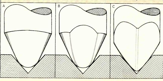
------ Spherical tip (A) is limited in tracking ability by its diameter. Elliptical tip (B) has contoured edges that permit better "fit" in the groove, improving tracking. Shibata tip (C) uses a boat-hull contour to improve tracking ability and increase the groove-contact area.
"If the stylus mistracks, the groove-wall destruction will be much worse than that produced by a little additional tracking force."
Tracking ability can generally be enhanced by selecting a tracking force to ward the high end of the cartridge manufacturer's suggested range. In fact, for best results, any cartridge should probably be used at close to its maximum recommended stylus force. This is not to say that a cartridge will not track some records at its minimum recommended force. But records are being cut at higher and higher levels, and chances are that in playing a significant part of your collection the cartridge will require all the help it can get, and a higher tracking force will provide that help. (Some records can't be tracked perfectly by any available cartridge, no matter what the force applied!) Obviously, the lower the tracking force, the less will be the wear and tear on the record and stylus. But if the stylus mistracks, the groove-wall destruction will be much worse than that produced by a little additional tracking force. Notwithstanding this readily apparent fact, test laboratories still have a problem establishing the point at which mistracking occurs. Is it a matter of measured distortion exceeding some arbitrary percentage? Is it the onset of the gross "shattering" sound that accompanies the stylus' complete loss of contact with the groove wall? We can't say, for no standard exists.
Neither does any standard exist for optimum stylus compliance. Compliance is a measure of the "give" of a stylus assembly. A large amount of compliance is good for the tracking of low frequencies (provided the stylus assembly doesn't collapse altogether), and for years cartridge manufacturers vied to publish the most spectacular figures they could. Recently they've turned away from this sort of compliance race, and for good reason.
First, compliance is usually measured under static conditions: push on the stylus with a calibrated force and measure the amount of movement resulting. But the movements imposed by record grooves are anything but "static."
At frequencies higher than very deep bass, the stylus needn't move very far, but the movements it does make must be very rapid. As the frequency goes up, the stylus' activity is controlled more and more by the frictional damping within the stylus assembly and, finally, by the effective mass of the stylus itself. Few good cartridges have difficulty reproducing organ-pedal notes. But they run into trouble at higher frequencies where simple static compliance measurements tell us nothing at all about tracking ability.
Compliance can also harm as well as help, as when it unfavorably affects the tone-arm/cartridge resonance of the system. The tone arm has, of course, an effective mass of its own, and the stylus is essentially a spring as far as the arm is concerned. Thus the stylus compliance resonates with the tone-arm mass at a certain easily calculated frequency. This is not a happy situation. At that (usually infrasonic somewhere below 15 Hz) frequency the stylus will undergo exaggerated motion that will be translated into low-frequency signals that tax amplifiers and speakers and generally muddy the sound with modulation effects. It will also tend to mistrack when so stimulated. Therefore, although this resonance may occur at a frequency too low to be perceived directly, its effects can easily communicate themselves up into the audio range.
This resonance cannot be entirely eliminated, but it can be controlled.
For example, it can be purposely fixed around 10 Hz or so-a good place for the arm-cartridge resonance, because that is below the frequency of any re corded music and yet above the frequencies at which record warps and other perturbations usually occur. The way to adjust the resonance frequency of the arm-cartridge system is by "tuning" it-juggling the effective mass of the system and the compliance of the stylus assembly: the lower the mass, the higher the resonance; the greater the compliance, the lower the resonance. For each model of tonearm there is an optimum range of cartridge compliance; neither more nor less is desirable.
This brings up the matter of matching the cartridge to the tone arm. A cartridge with very high compliance calls for an arm with very low effective mass, or the resonance will occur at a frequency within or very close to the major warp region (4 to 6 Hz or so). A low-compliance cartridge is therefore best served by an arm with greater mass, which prevents the resonance from occurring in the music region. But how can you determine the effective mass of a tone arm? In general, you can't, so avoid being taken in by appearances. Some arms look massy but have all their weight concentrated near the pivots where it doesn't affect matters. Other arms, though frail in general appearance, are overweight at the cartridge end of things.
WITH all these problems, it would be no surprise at all if some theoretician in the far-off future, never having heard of the phonograph, should gasp in astonishment at the idea of sound being stored in the form of physical undulations in a plastic groove. Indeed, even today, those who are best qualified to appreciate the electro-physical problems posed--and solved--by the concept remain somewhat amazed by the wonder of it all.
-------------
Phono Cartridge Manufacturers
ACUTEX, 246 W. Broad St., Falls Church, Va. 22046
AKG, North American Philips, 100 E. 42nd St., New York, N.Y. 10017
AUDIO DYNAMICS CORP., 230 Pickett District Rd., New Milford, Conn. 06776
AUDIO-TECHNICA U.S., 33 Shiawassee Ave., Fairlawn, Ohio 44313
BANG & OLUFSEN, 515 Busse Rd., Elk Grove Village, III. 60007
DECCA, Rocelco, Inc., 1669 Flint Rd., Downsview, Ont., Canada M3J 2J7
DENON, American Audioport, 1407 N. Providence Rd., Columbia, Mo. 65201
EMPIRE SCIENTIFIC, 1055 Stewart Ave., Garden City, N.Y. 11530
GRACE, Sumiko, P.O. Box 5046, Berkeley, Calif. 94705
GRADO LABS, 4614 7th Ave., Brooklyn, N.Y. 11220
MICRO-ACOUSTICS, 8 Westchester Plaza, Elmsford, N.Y. 10523
NAGATRONICS, 2280 Grand Ave., Bald win, N.Y. 11510
NAKAMICHI RESEARCH, 220 Westbury Ave., Carle Place, N.Y. 11514
ORTOFON, 122 Dupont St., Plainview, N.Y. 11803
OSAWA & CO,. 521 5th Ave., New York, N.Y. 10017
PICKERING & CO., 101 Sunnyside Blvd., Plainview, N.Y. 11803
SATIN, Osawa & Co., 521 5th Ave., New York, N.Y. 10017
SHURE BROS., 222 Hartrey Ave., Evanston, III. 60204
SIGNET, 33 Shiawassee Ave., Fairlawn, Ohio 44313 SONUS, P.O. Box 399, Danbury, Conn. 06810
STANTON MAGNETICS, Terminal Dr., Plainview, N.Y. 11803
SUPEX, Sumiko, P.O. Box 5046, Berkeley, Calif. 94705
---------------
====================
Also see:
The Engineers Have Their Say About PHONO CARTRIDGES (July 1966)
Turntables -- What Are Your Options (Jan. 1985)
HOW TO MAKE GOOD RECORDS (Jan. 1979)
Source: Stereo Review (USA magazine)