-------------
By Hirsch-Houck Laboratories
TANDBERG TD-20A
TANDBERG has been making high-quality open-reel recorders for more than a quarter of a century, and its latest model, the TD 20A, lives up to its distinguished heritage.
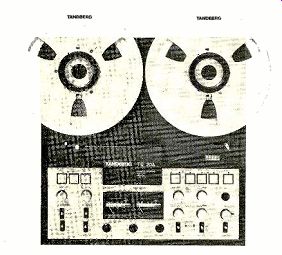
Capable of handling reel sizes up to 10 1/2 inches in diameter, it is available in either quarter- or half-track stereo formats and with either 15 / 7 1/2-ips or 7 ½, 3 3/4-ips speed options. The unit we tested had the quarter-track heads and 7 ½, 3 3/4 speeds used by most home recordists.
A total of four motors is used in the TD 20A. Each of the two reel tables is directly connected to its own drive motor for fast winding and takeup torque, and an a.c. synchronous motor is belt-coupled to the capstan.
The fourth motor replaces the customary solenoids in controlling the brake bands and the rubber pressure-roller mechanism. This produces very quiet, smooth operation, in contrast to the usual sharp "clack" of solenoids. The reel motors receive a short electrical impulse when the stop button is pressed after threading the tape, taking up any slack.
Spring-loaded tension arms on each side of the head assembly are similarly used to smooth the tape flow during normal operation, and a small precision roller inside the head nest acts as a "scrape-flutter" filter.
The heads themselves are of Tandberg's own design and manufacture, and are of ferrite, giving them exceptional resistance to wear. The playback head is fitted with a spring-loaded shield that swings into place when the tape gate closes; it provides additional protection against hum, but it does make it difficult to mark the tape for editing purposes. Inside the head assembly is an optical sensor that stops the deck in the event of a tape break or runout. A conventional four-digit counter registers the revolutions of the takeup reel.
The lower section of the TD 20A contains the controls and meters. Three large pushbuttons turn the machine on and off, set the speed to high or low (there is no variable pitch control), and select the proper tensions ...
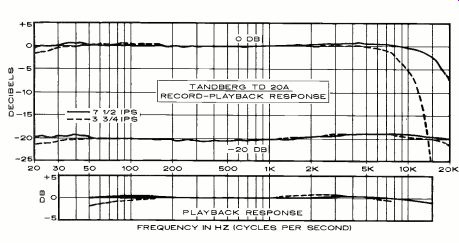
----- FREQUENCY IN HZ (CYCLES PER SECOND)
... for either large (10 1/2-inch) or small reel sizes.
Below these are separate left- and right-channel playback-level controls whose settings affect not only the outputs and headphone volume, but also the indications of the meters when the deck is in its playback mode.
Beneath the playback-level controls are four lever switches. A three-position PLAYBACK MODE switch connects the left channel to both outputs, the right channel to both out puts, or, in its STEREO position, each channel to its appropriate output. The MONITOR switch permits direct comparison between the signal fed to the tape and a playback of the same signal a split-second later. A SEL. SYNC. switch permits a previous recording made on the left channel only to be synchronized with a new recording made on the right channel by temporarily converting the left-channel re cord head to a playback function. And an EDIT/CUE switch activates the playback amplifier when the deck is stopped or in a fast-winding mode to facilitate finding a precise spot on the tape. One note of caution is in order: when using the CUE function during high speed winding, turn down the playback level to prevent tweeter damage.
On the right side of the electronic section are five large pushbuttons, each with its own LED indicator, for RECORD, REWIND, STOP, WIND, and PLAY. All of these operate through integrated-circuit logic control, so no sequence of commands can snarl or break the tape. If the STOP and WIND buttons are de pressed and then released simultaneously, the deck enters a FREE mode (also signaled by a LED indicator) in which the reel brakes are released, facilitating tape threading. If either or both of the two RECORD SELECTOR switches is shifted to ON, a STAND BY indicator is illuminated. In most tape decks, the record mode can be entered only by depressing the RECORD and PLAY buttons at the same time, but Tandberg has chosen to follow the professional practice of using record-selector switches in conjunction with a separate RE CORD button. This allows the record mode to be entered directly while the tape is running, though for such "flying start" or "punch-in" applications it is also necessary to keep the PLAY button depressed.
Below these pushbuttons are four input-level controls plus a master input control. The INPUT 1 pair is dedicated to "line-level" sources (a preamplifier's tape-out jacks or another recorder, for examples), while the INPUT 2 pair can be used to mix in either micro- phones, a second line-level component, or a "radio" output plugged into the European DIN-B socket on the rear panel. The master level control has an adjustable ring with a detent to allow return to a predetermined set ting when fading in or fading out. A DIN-type jack for an accessory remote-control de vice and a microphone-sensitivity switch that inserts a 25-dB attenuator to prevent overload when using high-output microphones are also located on the right side of the front panel.
In the center section are jacks for head phones (nominal 8-ohm impedance, though we experienced no difficulty in using 600-ohm types) and a pair of microphone inputs that are rated to accept either balanced or unbalanced microphones of low to medium impedance (50 to 700 ohms). Above these jacks are the illuminated meters (indicating from-24 to +3 dB), which, in conformity with a long standing Tandberg design philosophy, are not only peak reading (rather than VU) but are "equalized" as well. This means that during recording they register the effect of the necessary record high-frequency equalization, so they do not give the same reading for the same signal level at all frequencies. While this is an annoyance to a tester or equipment reviewer (record and playback levels cannot be made to agree on the meters, for example), it does assure the user that, no matter what the frequency content of the music, so long as the indicators do not exceed the 0-dB marking he will get a virtually undistorted recording.
The rear panel of the TD 20A contains the necessary input and output jacks, which are inset into a cavity so that the deck can be operated in either a vertical or a horizontal position. The overall measurements of the TD 20A are 17 1/4 inches wide, 17 3/4 inches high, and 6 inches deep (not including the front-panel knobs); it weighs approximately 37 1/2 pounds. Price: $1,500.
Laboratory Measurements. The Tandberg TD 20A comes factory-set for use with Maxell UD-XL. tape (which we used for our measurements), though it has screwdriver-accessible bias-adjustment holes on the front panel that permit optimization for nearly any conceivable tape type-including open-reel metal tapes, should these ever become available.
Playback equalization was checked using standard Ampex test tapes, which, within their frequency limits, showed near-perfect response as indicated in the graph. Overall frequency response, measured at the customary-20-dB level with the recommended Maxell UD-XL tape, was so flat at both 71/2 and 33/4 ips that drawing the "curves" was essentially an exercise in futility. Response was not down by more than 3 dB at the low-frequency end until a frequency of 11 or 12 Hz was reached, and in the high-frequency region the-3-dB points extended to 21 kHz at 33/4 ips and to 33 kHz at the 71/2-ips speed. At a 0-dB level the differences in high-frequency potential show up more clearly, yet even here the curves are perhaps slightly misleading: since the record-level meters are equalized, they deflected well off-scale at the higher frequencies when using the 33/4-ips speed, plainly warning the user to re duce the overall record level. Though making a straightforward frequency-response curve at this level overloaded the tape capacity, it did not overload the record amplifier, with its "Actilinear" circuit.
Because the TD 20A uses peak-reading rather than average-reading meters, it re quires little or no headroom allowance to compensate for meter ballistics and un foreseen signal peaks. Distortion of a 1,000-Hz tone recorded at an indicated 0-dB level was less than 1 percent at either speed, and the customary 3 percent third-harmonic distortion level used for making signal-to noise ratio (S/N) measurements was reached with an input level of +4 dB-1 dB above the meter scale. Unweighted S/N, referred to the output at this level, was 62 and 59.5 dB for the 71/2- and 33/4-ips speeds, respectively. Applying the customary IEC A-weighting curve improved the figures to 69 and 66 dB.
Wow and flutter was extremely low at 7 1/2 ips, measuring between 0.015 and 0.018 percent (wrms) and between 0.02 and 0.03 percent on the stricter DIN-B peak-weighting standard.
At 3 3/4 ips the figures increased to 0.055 and 0.1 percent, respectively.
At the inputs, a signal level of 35 millivolts (mV) was required to produce a 0-dB indication when using the LINE 1 inputs, and the maximum output at this level was 1.2 volts. A signal level of 0.15 mV produced the same reading at the microphone input, and the overload point was reached at 24 mV. The 25-dB microphone attenuator raised these figures correspondingly. The fast-forward and rewind times for a 1,800-foot tape on a standard 7-inch reel were identical at 90 seconds.
Comment. We would have preferred slightly larger meters and wish that when switching from "source" to "tape" during the re cord process the meters were switched as well (the meters read playback levels only in the play mode). And we wish that there were space in the head nest for a second (half track) playback head so that tapes recorded in either format could be played. But these are only minor cavils.
Listening tests using a wide variety of material confirmed the excellent measurements we obtained. Even making copies of master tapes of live musical performances produced no audible loss of frequency response and added only the slightest amount of hiss, which is inherent in any dubbing process. In the several months we have used the TD 20A it has yet to snarl a tape, and it is so quiet in operation that we have several times inadvertently left it running without being aware of it. The Tandberg TD 20A is a superb audiophile deck, and, while not inexpensive, it is certainly well worth the price.
MXR Dynamic Expander
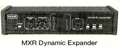
SINCE its inception, the MXR brand name has been associated with signal-processing devices of various kinds (mostly for the professional user). Their new dynamic ex pander, which complements the MXR graphic equalizers and other instruments, is a single-pass device meant to be inserted into the tape-recording/monitoring loop of an amplifier or receiver (or between the preamplifier and power-amplifier sections, although that is less desirable since the signal will be affected by tone and volume controls before being expanded). It expands the dynamic range of the program linearly and equally for all frequencies and levels, and it requires no critical gain adjustments.
To restore the tape-monitoring function of the component to which it is connected, the MXR dynamic expander has duplicate tape-input and-output jacks on its rear apron and a front-panel tape-monitor switch button.
Another button makes it possible to expand the program before it is recorded (PEE) or to expand the playback from the recorder (nos-r). A third INPUT button bypasses the ex pander circuits. There is also a power push button; if desired, the MXR unit can be plugged into a switched outlet of the amplifier or receiver and controlled by the main power switch.
The MXR dynamic expander is finished in flat black with clearly contrasting white panel markings and wood side panels. In addition to the previously mentioned pushbutton switches, it has three knob-operated controls.
The RELEASE TIME knob controls the rate at which the expander gain returns to normal after expansion. It is adjustable over a range of approximately 50 to 500 milliseconds (corresponding to the FAST and stow panel markings). The attack time is fixed at about 5 milliseconds or less, depending somewhat on the program material. As a rule it is desirable to have the fastest possible expansion rate, but not so fast as to follow a very-low-frequency waveform (which would cause distortion).
The EXPANSION control changes the slope of the OUTPUT/INPUT transfer characteristic continuously between the limits of 1.0 and 1.6. The former represents a non-expanded condition in which a 10-dB change in input level will result in a 10-dB change in output. The other extreme will give a l6-dB change in output for every 10 dB of change in input. In most cases, an intermediate setting will be found most satisfactory.
The LEVEL control is used to optimize the operation of the expander roughly with respect to the signal level. Though critical, it is useful for adjusting the relative amounts of upward-gain shift (expansion) and down ward-gain shift (noise reduction) imparted by the unit to any given program.
In the center of the panel is a vertical array of red LEDs that monitor the expander operation. They show the instantaneous gain of the device, from +6 to -18 dB, in 3-dB steps over most of that range. When the 0-dB light is on, the expander gain is unity (no expansion or noise reduction). The LEVEL control is normally set so that the 0-dB light is on at average program levels. When the input level drops, the expander gain drops with it, reducing the background noise by a corresponding amount. A high-level passage will increase the expander gain to +3 or even +6 dB, with a corresponding boost of signal level over the unexpanded condition.
The operating instructions of the MXR dynamic expander explain clearly how to adjust the controls, which must be set by ear in accordance with the program and one's listening preference (in other words, there is no "correct" setting). Its own signal-handling ability (the maximum rated input and output are, respectively, 4 and 8 volts) is well in ex cess of the levels it will have to handle in any operating music system. The frequency response is essentially flat over the audio range, and distortion is well below audibility (al though the unit's distortion is a function of its instantaneous expansion as well as the signal-input level and frequency).
The input to the MXR dynamic expander, after buffering to isolate the expander circuits from the amplifier's tape-output circuits, is divided into separate signal and control paths.
The control path contains a rectifier that produces a d.c. voltage proportional to the rms value of the complex program waveform (it is not clear in the literature from MXR whether this is a true rms detector or an average-responding detector). The control signal is de rived from the sum of the two input channels and affects the signals in both channels equally to prevent lateral shifts of gain that would disturb the stereo-image position.
After passing through circuits that adjust the attack and release time constants, the control signal is compared with a reference voltage and the difference is used to control the gain of a voltage-controlled amplifier (VCA) through which the signal passes. The display on the front panel is also operated by the control signal. The MXR dynamic expander is 18 inches wide, 4 inches high, and 6 1/4 inches deep. It weighs approximately 6 1/2 pounds. The suggested retail price is $300.
Laboratory Measurements. Because of the MXR expander's dynamic nature, our laboratory measurements, were naturally limited to its steady-state input/output transfer characteristic, distortion, and frequency response.
With the EXPANSION control set to 1.0 (no expander action) the frequency response of the MXR expander was flat across most of the audio band and was down only 0.3 dB at 20 Hz and 0.2 dB at 20,000 Hz. At full expansion (1.6), the response at the lowest frequencies dropped off to about-6 dB at 20 Hz, but from 100 to 20,000 Hz the total variation was about I dB.
The maximum input before waveform distortion occurred was 3.7 volts, and the maximum unclipped output was 9.3 volts. With a 1.0 expansion slope, the distortion at either 1,000 or 20,000 Hz was less than 0.01 percent at a 0.3-volt output or less, increasing slowly to 0.014 percent at I volt and 0.07 percent at 3 volts. The 20-Hz distortion was higher (though still negligible), measuring 0.016 percent at 0.1 volt, 0.06 percent at I volt, and 0.22 percent at 3 volts output.
At full expansion (1.6) the distortion at 1,000 Hz was no more than 0.025 percent up to 0.3 volt and 0.089 percent at 3 volts out-put. The 20,000-Hz readings were about 0.02 percent or less up to 1 volt and 0.13 percent at 3 volts. At 20 Hz, the distortion was a constant 1.3 percent from 0.3 to 3 volts.
The measured slopes of the expander characteristics were considerably less than the values shown by the panel markings. The 1.0 slope was correct, but the 1.3 setting produced a slope of about 1.25 dB down to-30 dB and only about 1.15 dB over a full input range of 60 dB (which resulted in an output change of about 68 dB instead of the expect ed 78 dB). With a "1.6" slope, the actual out put/input ratio was about 1.5 near the upper end of the output range, but only 1.25 dB over the full 60-dB range. For these measurements, we set the "0 dB" level to give 3 volts output (at 1,000 Hz) and reduced the input in 10-dB steps over a 60-dB range.
Comment. The audible performance of any dynamic signal processor cannot be judged from conventional measurements; therefore, our only purpose in making bench measurements on the MXR expander was to confirm its basic electrical performance and to detect any possible level or impedance in compatibility with other system components.
There were none, and its electrical quality was obviously of a fully "hi-fi" caliber.
Anyone using a dynamic expander for the first time will inevitably use it to excess, if only to judge the limits of audible effects on the program. MXR suggests doing just that with their dynamic expander, to exaggerate the degradation of program quality that can result from the injudicious application of this type of signal processor. Having done that, the user is advised to alter the control settings for the best compromise between sonic improvement and undesirable side effects.
Any signal processor must be used with discretion; if its action is obvious, then it is ipso facto excessive. In most cases, when we used an expansion slope of 1.3 or less, the action of the expander could not be detected (except by bypassing it, which can be a very convincing demonstration of its noise-reducing capabilities). Higher settings than 1.3 can too easily result in an audible surging of pro gram level or background noise, and lower settings may not produce sufficient expansion.
In general, we found that the benefits of dynamic expansion lie more in the downward part of the expansion characteristic which reduces background noise during quiet passages (this is true of all of today's expanders, not merely the MXR unit). If the hiss in the in coming program is plainly audible without expansion, it will almost always be heard "swishing" up and down with program-level changes. A long release time is helpful in such a case. The quieter the incoming pro gram, the more effective will be the overall expansion process. This comment applies equally to the several types of "single-ended" noise-reducing devices available to the audiophile (dynamic filters, auto-correlators, and the like). None of them do very well with re ally noisy material, but their effectiveness in creases dramatically as the quality of the pro gram improves.
A highly compressed program (such as most pop or rock music) will not be expanded or otherwise improved with the expander, since it has no significant dynamic range to begin with. On the other hand, the sound of a fairly wide-range recording with low surface noise can often be improved from "good" to "spectacular." Between these limits, most programs will be improved to some extent by proper expansion. Although one would rarely wish to expand a program before taping it, this feature of the MXR expander can be useful when dubbing old discs having noisy surfaces and limited dynamics.
The question that can be answered only by the prospective purchaser of a dynamic ex pander such as the MXR is "Are the possible benefits worth the rather large investment?" Everyone will have to make his or her own decision on that matter. From our experience with the MXR dynamic expander, we can say that it does its job effectively, subject only to the limitations inherent in its product category and the ability of the user to adjust it properly to the program material.
Electro-Voice Interface: C Series II Speaker System
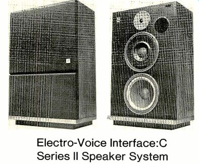
THE Electro-Voice Interface line of speaker systems, originally introduced in 1973, is now in its third generation. The current line includes seven systems, ranging from "book shelf" size to large, floor-standing units. One of the larger is the Interface:C, which is now in its "Series II" form. It is a floor-standing, three-way system based (like all the others) on an "optimally vented" woofer built ac cording to criteria established by researcher A. N. Thiele.
Thiele's analysis of vented speakers makes it possible to design a speaker system to satisfy a wide range of requirements in respect to low-frequency response, distortion, size, and efficiency. E-V's goal was to create a speaker considerably more efficient than acoustic-suspension types, yet with a low-distortion response extending smoothly to 30 Hz or be low-and in an enclosure of reasonable size.
The specifications of the Interface:C Series II suggest that they have done their work well. It is not small, measuring 31 1/2 inches high, 20 inches wide, and 12 1/2 inches deep, but neither is it obtrusively large. The walnut-veneer cabinet is attractively faced with a brown cloth grille, and the system weight of 60 pounds is no more than that of some so-called "bookshelf" speakers we have seen.
The woofer, nominally 10 inches in diameter, is vented by a ducted port 4 inches in diameter. At 400 Hz there is a crossover to a novel E-V midrange driver design, the VMR II (VMR stands for "vented midrange").
This 6 1/2-inch cone speaker uses the same massive (5 pounds, 12 ounces) magnet structure employed in the woofer. It is fully sealed around the back, with the enclosed volume filled with sound-absorbent material. The midrange driver is also vented through a slot on the front of the speaker housing. The VMR design enables the midrange driver to deliver a flat response, down to the 400-Hz ...
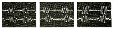
---- The generally good tone-burst response of the Interface:C Series II speaker is shown at (left to right) 100, 1,000, and 10,000 Hz. The input-signal traces are at the top in the oscilloscope photos.
... crossover frequency, with low distortion, high power-handling ability, and an efficiency matching that of the woofer. Also, the small size of the midrange cone provides the necessary dispersion.
The second crossover, at 2,500 Hz, is to an E-V "Super Dome" tweeter. Basically a dome radiator, it is front-loaded by a plastic-foam acoustic lens that improves its dispersion at high frequencies. The voice coil has been designed to handle 25 watts continuously (about five times the power-handling ability of typical conventional tweeters), and its efficiency is also several times higher than that of ordinary dome tweeters.
Inherent in the Thiele-based design of the Interface:C Series II woofer is the use of an equalizer (as an alternative to using a very large enclosure) to flatten out and extend its low-bass response to 30 Hz. The equalizer, which can be connected either in the tape-monitoring path of an amplifier or between the preamplifier and the power amplifier, has unity gain and negligible noise and distortion. It boosts the response gradually below 200 Hz to a maximum of +6 dB at 35 Hz with a controlled rolloff below that frequency to eliminate infrasonic components that could cause noise or distortion. It also has two optional degrees of high-frequency rolloff in addition to a flat-response condition (in lieu of tweeter-level controls).
The equalizer is a small black box, 2 inches high, 8 inches wide, and 7 inches deep.
It is self-powered, with a four-position switch controlling the power and the treble response (0, 3, and 6 dB of attenuation at 10,000 Hz).
Another switch replaces the tape-monitoring functions when the equalizer is connected into the amplifier's tape-monitoring path.
The performance of the E-V Interface:C Series II is specified with unusual complete ness. Its rated response is ± 2.5 dB from 30 to 18,000 Hz in an on-axis measurement taken at 1 meter (presumably anechoic), and it is recommended for use with amplifiers delivering from 2.8 to 350 watts per channel (which must surely include every amplifier ever sold for high-fidelity use in the home). A 1-watt input is rated to produce a sound-pressure level of 93 dB at 1 meter, and the maximum available long-term average level in a normal listening room is an ear splitting 111 dB! The system impedance is nominally 6 ohms, with a 4-ohm minimum rating. The E-V Interface:C Series Il is sold only in pairs, including the equalizer. The price of the complete system is $995.
Laboratory Measurements. All our measurements of the E-V Interface:C Series II were made through its equalizer. We also measured the frequency response of the equalizer separately. As is our usual practice, the integrated speaker response in the reverberant field of the room was spliced to the close-miked woofer response to form a composite curve.
The response at middle and high frequencies was extraordinarily flat, varying only ±1 dB from 550 to 10,000 Hz. The woofer response, not quite so flat, was nevertheless excellent and was maintained to the lowest audio frequencies. The combined response curve showed a variation of ± 2.5 dB from 30 to 17,000 Hz, an impressive result for a measurement made, for the most part, at a typical listening position in a normal room about 12 feet from the speakers.
The dispersion of the "Super Dome" tweeter and the VMR midrange driver was essentially perfect for normal stereo listening. By that we mean that the curves made at a single microphone position, on the axis of the left speaker and 30 degrees off the axis of the right speaker, were effectively identical over the entire range from a few hundred hertz to 20,000 Hz. This is what we expect to measure from good omnidirectional speakers; it is exceedingly rare in front-firing speakers.
The system impedance varied between 3 and 8 ohms over most of the audio range, with maximums of 10 ohms at 25 Hz and 16 ohms at 64 Hz. The 6-ohm nominal ratting seems justified, although in our measurements the minimum impedance reached 3 ohms at 1,000 Hz and between 5,000 and 10,000 Hz. We would not suggest paralleling two Interface:C Series Il systems on a single amplifier, although the E-V instruction manual implies that this is acceptable.
The high sensitivity of the E-V Interface:C Series II was confirmed by our measurement of a 94-dB sound-pressure level at 1 meter when we drove it with 2.83 volts of random noise in an octave centered at 1,000 Hz. Not only is this 8 to 10 dB more efficient than many acoustic-suspension systems, but it rivals the most efficient vented speakers we have tested in recent years and is combined with superior low-bass performance.
The low-frequency distortion was low, about 1percent down to 50 Hz at a 1-watt (2 volts) drive level and increasing to 7 percent at 80 Hz. At a 10-watt level, the distortion was about 2 per cent down to 65 Hz, reaching 10 percent at 35 Hz. Bearing in mind the rather high acoustic output that is produced by even a 1-watt input, this indicates a very low effective distortion level under any reasonable listening conditions. The tone-burst response, at several frequencies in the audio range, was good though not outstanding.
Comment. At the time we were evaluating the E-V Interface:C Series II, we had on hand several other speakers that might be considered as competitive in respect to size or cost. Not unreasonably, they were also competitive in listening quality, which made our task both easier and more difficult.
The problem is that when judging speakers selling for $500 each or more, one expects and usually receives-correspondingly good sound. Naturally, all speakers sound different to some degree, and that degree might be determined by the way they interface with the specific environment in which they are playing. How does one make a reasonably objective selection from among a group of speakers that are about equally pleasing-or accurate-but which have slightly different sonic qualities? We can answer that question only in a rather oblique manner. In truth, over the years we have encountered a few systems selling for $500 or more that really sounded very bad. Needless to say, those speakers did not receive reviews in these pages. Among the good ones, we have found that it is easy to become accustomed to the particular sound quality of any really fine speaker. The differences to be heard are analogous to the change in the sound of an orchestra when heard from different seats in a good hall.
In the case of the Interface:C Series II we could not pick out any particular instrument that it favored or discriminated against. It simply sounded as smooth and clean, as "good" in every respect, as we could wish from any speaker. It has a full measure of highs, middles, and lows, with no lack or emphasis in any part of the spectrum. We were never driven to switch it off in favor of some other speaker (this is perhaps the highest accolade I can bestow on any product).
The nearly ideal manner in which the Interface:C Series II "measured" no doubt influenced our feelings; we often face the problem of explaining or justifying a subjective preference that is not obviously correlated with measurements. Not so in this case: the Interface:C Series II measures about as close to ideal as can be expected under the test conditions we use, and it sounds every bit as good as its curves indicate. Also, the fact that these speakers do not require weight-lifting skills to unpack or move around may have contributed something to our positive reaction! E-V has clearly done so many things right and so few wrong (actually, we didn't find any "goofs" in this speaker, but we assume that no one-even E-V--is absolutely perfect) that we were just plain impressed with the final result.
--------
Dual 506 turntable and Dual/Ortofon ULM 55E Phono Cartridge
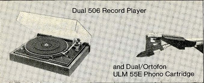
THE Dual 506 is a single-play record player i whose only automatic feature is an end-of-play arm lift and motor shut-off (the arm remains in place and must be returned manually to its rest). The cast-aluminum platter is belt-driven at 33 1/3 or 45 rpm, the speed being selected by a lever on the motorboard that shifts the belt to different drive-shaft diameters. A vernier speed-control knob, concentric with the speed selector, expands the drive shaft slightly to vary the speed ±6 percent at 33 1/3 rpm. Stroboscope markings on the edge of the platter are illuminated by a neon lamp.
The Dual 506 features a newly designed ULM (Ultra Low Mass) tone arm whose effective mass (less cartridge) is only about 5.5 grams (one-third to one-fourth the mass of most contemporary record-player tone arms). With its straight tubular construction and low-friction gimbal bearings, it bears a general resemblance of former Dual tonearms. With minor differences, principally in the counterweight, the new ULM tonearm design is used on all current Dual record players.
The arm is balanced by a threaded counterweight, and tracking force is applied by a spiral spring acting around the vertical-pivot axis. A knob on the side of the pivot structure is calibrated from 0 to 3 grams (at 0.1-gram intervals from 0.2 to 1.5 grams and at 0.25-gram intervals from 1.5 to 3 grams). The antiskating dial has scales for conical and elliptical styli.
The turntable is started by moving the arm from its rest. At this point, the cueing lift is in the UP position, so that the arm can be moved over the desired part of the record by a light horizontal push. A flip of the cueing lever lowers the pickup to the record with a smoothly damped motion. If the arm is lifted manually and returned to its rest, it automatically moves the cueing lever to UP as it en ters the rest, shutting the motor off at the same time. At the end of a record, the arm simply lifts and remains in place, but the mo tor shuts off.
Like all Dual record players, the 506's components are mounted on a single steel plate that is isolated from the wooden base on springs. The synchronous motor is further isolated from the motorboard by a compliant suspension. The clear plastic dust cover is hinged to remain fully open, closed, or at intermediate angles.
The tone arm is the truly unique part of the Dual 506. Despite its apparent similarity to previous Dual arms, it is constructed of a smaller-diameter and lighter-weight tubing.
Dual's familiar plastic cartridge mount has been eliminated in the interest of keeping arm mass to a minimum. More than that was required, however. Most cartridges weigh between 5 and 8 grams, and all of the weight effectively appears at the stylus location. One could not hope to achieve Dual's goal of an 8-gram total effective mass with a cartridge that weighed almost that much Dual therefore joined forces with Ortofon in adapting the Danish manufacturer's new LM cartridge design (used in their Concorde series) to Dual's needs. The 2.5-gram mass of the Dual ULM cartridge (including mounting bracket and hardware) makes it ideal for use in a ULM system. Although cartridge installation is slightly less convenient than in previous Dual players, it presents no real problem. The 506, like all the other current Dual models, is available with a factory-installed ULM cartridge, thus sparing the user one of the most onerous and critical chores in setting up a music system.
However, Dual has not ruled out the use of other cartridges in their record players. A mounting adapter and overhang adjustment jig are supplied with the 506, and the arm will balance cartridges weighing between 2 and 9 grams (with the aid of an additional counterweight section for the heavier types).
The chief difference from the former mounting procedure is that the leads from the arm must be attached to the cartridge before it is actually mounted. The cartridge is held in place by a single screw.
The ULM cartridge comes in three models whose stylus characteristics complement the requirements of the associated record-player arm. In the case of the Dual 506, a ULM 55E is supplied. It is fitted with a 0.2 x 0.7-mil biradial (elliptical) stylus rated to track at 1.5 grams. The stylus is easily replaceable, sliding off the end of the cartridge when the finger lift is moved to the rear (as was done in former Dual arms to release the entire cartridge mount). To safeguard the stylus against theft (in stores or showrooms), a self-tapping screw can be installed in a second hole in the arm-mounting plate. It prevents the stylus from being removed by locking the finger lift in place. The stylus assembly carries a hinged plastic guard. The Dual 506 (without cartridge) is $189.95. With a factory-installed ULM 55E cartridge it is less than $299.95.
Laboratory Measurements. The Dual 506 tested for this report was supplied with the ULM 55E cartridge. As mounted, the tracking error was less than 0.33 degree per inch over the surface of a 12-inch record, and essentially zero at most points. When the arm had been balanced, the calibration of the tracking-force dial was exact (except for a barely measurable 0.05-gram error at I gram). We used the recommended 1.5-gram force during our tests.
The total effective mass of the arm and cartridge was 7 grams (slightly less than the rated 8 grams, but well within the normal un certainties of this type of measurement). The low-frequency resonance measured with a Denon 7001 test disc was at 14 to 15 Hz with an amplitude of about 5 dB. However, Dual's measurements with the German DIN 45543 test disc show a lateral resonance at 9.8 Hz and a vertical resonance at 11.5 Hz. The question of which figures are truly representative of the Dual 506's tone-arm/cartridge resonance is under investigation.
The antiskating calibration was nearly correct, although we found that setting it to 2 grams gave optimum compensation with a 1.5-gram tracking force. The cueing device followed Dual's tradition of being free of any lateral drift during arm descent. It was also exceptionally easy to use and had no tendency to jar or displace the tone arm.
The turntable itself ran smoothly and quietly. The vernier control had a range of ± 5.3 percent at 33 1/3 rpm and +3, -1.5 percent at 45 rpm. When the lower speed was set exactly, the 45-rpm speed was 0.5 percent fast.
Although it could easily be set to the correct value, an error of this magnitude can be ignored in most cases. The speed vernier knob had a distinctly "rubbery" feel, and consider able care was needed to set the speed exactly.
The turntable speeds were not affected by line-voltage changes from 95 to 135 volts.
The unweighted rumble was -28 dB, improving to-56 dB with ARLL weighting.
These figures are consistent with our past experience with moderate-price belt-driven turntables using synchronous line-powered motors (as opposed to electronically driven servo-controlled motors, either direct-drive or high-speed). Although the measured rumble was slightly higher than we have found on more elaborate or expensive turntables, it was quite negligible from a listening standpoint. The flutter was ±0.13 percent weighted peak (DIN) and 0.08 percent wrms (JIS). Both the rumble and flutter-frequency spectra were mostly below 10 Hz.
ALTHOUGH the ULM 55E cartridge is not available separately, we measured its performance to assess its place among today's cartridges. Its output at 3.54 cm/sec was 4.9 millivolts, with channel levels balanced with in 0.27 dB. The vertical stylus angle was 28 degrees. At its rated force, the cartridge easily tracked our high-velocity test records, including the 80-micrometer level of the Ger man HiFi Institute record.
The high-frequency tracking distortion of the cartridge, playing the shaped tone bursts of the Shure TTR-103 record, was reason ably low, increasing from 0.85 to 1.65 percent as the velocity went from 15 to 30 cm/ sec. However, lower-frequency intermodulation-distortion measurements with the Shure TTR-102 test record produced some rather strange results which we cannot explain (this particular measurement is also one of the most difficult to correlate with any audible property of a cartridge). The ULM 55E did not mistrack significantly at the record's maximum level of 27 cm/sec, which is a severe test. On the other hand, its intermodulation distortion did not drop as much at lower velocities as we would normally expect, reading 4 percent at 7 cm/sec. The important conclusion from this test, however, is that the ULM 55E can cope with the highest velocities likely to be found on commercial discs.
When we measured the frequency response of the ULM 55E, using a 47,000-ohm load and only the capacitance of the record-
player's arm and signal cables, the output rose by about 5 dB at 20,000 Hz following a long, smooth decline in output from 500 to about 10,000 Hz. Dual's recommended total of 400 picofarads resulted in a response flat within ±1.5 dB from 40 to 20,000 Hz with the CBS STR100 test record. Slightly different results were obtained with the JVC TRS-1005 and B&K QR-2009 records, but we felt that the response with the STR100 was at least as valid as any of the others. The square-wave response with the CBS STR112 record was good, with a couple of cycles of moderate-level ringing at slightly over 20,000 Hz.
Channel-separation measurements are closely dependent on the relationship be tween the cartridge under test and the geometry of the cutter head used to produce the test disc. The JVC record provided slightly better separation figures than the others, averaging 25 dB through much of the audio range, while the CBS and B&K records showed separations of 17 to 20 dB. The exact numbers are not very important, since even 17 dB is adequate for a full stereo effect. What is noteworthy about the ULM 55E is the uniformity of its channel separation across the entire audio range. Even at 20,000 Hz, the separation is about 15 dB.
Also, the crosstalk curves of the two channels are unusually symmetrical. We detected several small "glitches" in the crosstalk-response curves at 90, 160, and 400 Hz, apparently the result of resonances in the arm or cartridge structures. They did not appear in the direct-response curves, nor were they audible.
The isolation from external shock and vibration provided by the turntable base and mounting springs was about average for similar belt-driven turntables and not unlike that of Dual models we have tested in the past. The only significant transmission through the base was at 40 Hz.
Comment. Dual has taken a rather bold step by incorporating a radically new integrated arm and cartridge in their entire product line, and, as we see it, they have come off very well in the process. We welcome the appearance of ultra-low-mass pickups in moderate-price record players.
What does the ULM arm and cartridge combination do for the user? Unlike most of the "improvements" touted in new products, the benefits here are neither subtle nor subject to much argument. The Dual pickup sys tem tracked the most severely warped records in our collection, usually so well that we heard nothing wrong. Sometimes there was a trace of wow when the pickup climbed over a warp of 0.25 inch or more, but in the past such a record was destined for the discard pile.
The Dual 506 handles "normal" records with the greatest of ease. It has none of the quirks of automatic turntables (the arm will never go anywhere but where you place it, and there are no unexpected turn-offs or cy cling operations). The fact that the cueing lift is "up" whenever the arm is on its rest means that the pickup can be moved across a disc by a simple lateral push without any concern about keeping the stylus safely above the record. Everything feels "just right," and the Dual cueing system (traditionally one of the best in the business) puts the stylus exactly into the groove below it instead of a little ahead (in our experience, a non-drifting cueing system is about as rare as an un-warped record). Finally, at the end of play, the "automation" is a bare functional minimum, lifting the arm and shutting off the motor. A slight push will then return the arm to its rest.
Dual's ULM system, in combination with a balanced arm that uses a spring to set its downward force, is remarkably insensitive to jarring. The entire record player can be shaken quite vigorously without dislodging the pickup from the groove. Since this will often cause wow due to the rocking of the motor on its mounts, we would not suggest operating the 506 in a moving vehicle, but it does demonstrate that the stability of its tone arm is well above average.
As for the sound of the Dual 506/ULM 55E, if you like a very flat, uncolored sound (as we do), it is hard to beat an Ortofon cartridge, and the combination is a most felicitous one at a really affordable price.
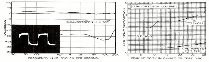
------- In the graph at left, the upper curve represents the smoothed, aver aged frequency response of the cartridge's right and left channels; the distance (calibrated in decibels) between it and the lower curve represents the separation between the two channels. The inset oscilloscope photo shows the cartridge's response to a recorded 1,000-Hz square wave (see text), which indicates resonances and overall frequency response. At right is the cartridge's response to the intermodulation-distortion (IM) and 10.8-kHz tone-burst test bands of the TTR-102 and TTR-103 test records. These high velocities provide a severe test of a phono cartridge's performance. The intermodulation-distortion (IM) readings for any given cartridge can vary widely, depending on the particular IM test record used. The actual distortion figure measured is not as important as the maximum velocity the cartridge is able to track before a sudden and radical increase in distortion takes place. There are very few commercial phonograph discs that embody musical audio signals with average velocities much higher than about 15 cm/sec.
==============
AD (Dual)
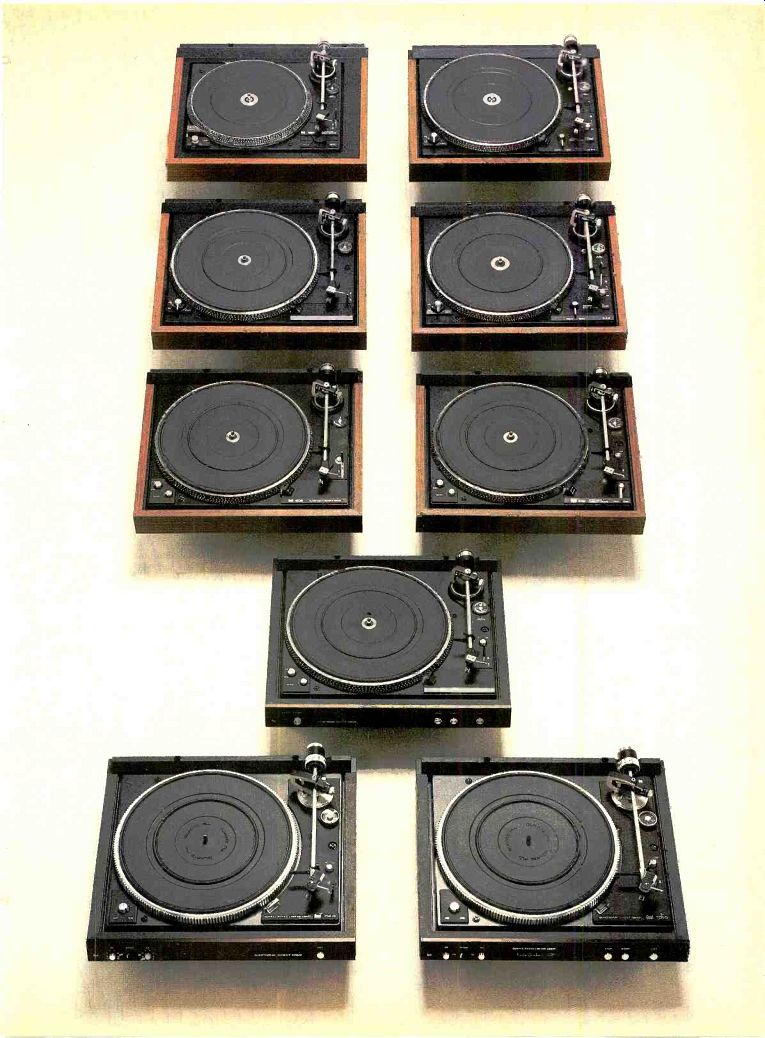
All nine new Dual turntables feature ULM...the Ultra Low Mass tonearm and cartridge system with 8 grams total effective mass.
All it takes to appreciate the significance of Dual's new Ultra Low Mass system is a clear understanding of what happens when the stylus tracks warped records.
As the record warp rises and falls, the stylus should be able to follow it with a minimum of resistance from the tonearm. Otherwise, tracking angle and tracking force will vary widely as the stylus digs in on the way up the warp and takes off on the way down.
The high inertia of a conventional tonearm and cartridge combination, with approximately 18 grams total effective mass, can cause tracking force to vary as much as 30 percent.
And a warp as small as 1.5 mm (barely discernible) can generate harmonic distortion of 2.7 percent. That's audible.
The new Dual ULM tonearm and cartridge system has only 8 grams total effective mass. Tracking the same warped record under the same conditions, harmonic distortion is reduced to only 0.01 percent. That's 270 times less! Not only is the overall sound audibly improved, but stylus and record life are significantly extended.
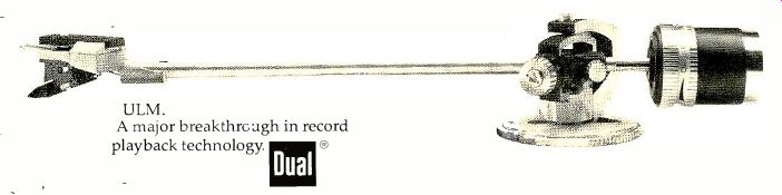
What has made the ULM system possible? First, Dual's straight-line tubular tonearm with its gyroscopic gimbal suspension and unique system for setting tracking force without increasing effective mass. This tonearm can now accept a cartridge weighing as little as 2 grams. Second, a new generation of cartridges that resulted from a collaboration between Dual and Ortofon. These ULM cartridges weigh only 2.5 grams, including mounting bracket and hardware.
Together, the new ULM tonearm and ULM cartridge form a perfectly matched system, with total effective mass less than half that of conventional tonearms and cartridges.
To experience the demonstrable advantages of ULM, bring a badly warped record to your Dual dealer. Listen to it when played with the ULM tonearm and cartridge system. You will hear the difference that ULM can make on all your records. Then you need only decide which of the nine new Dual turntables best meets your requirements for convenience and refinements.
--- Prices begin at less than $180 for the multiple play model 1257. The top model, the automatic single-play 731Q with quartz PLL direct drive, is less than $560. ULM cartridges are optional. For the complete ULM story, please write to: United Audio, 120 So. Columbus Ave., Mt. Vernon, NY 10553. ULM.
A major breakthrough in record playback technology. Dual
Audio Pro TA-150 AM/FM Stereo Receiver
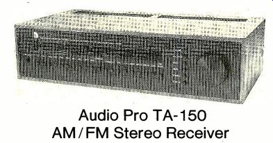
THE Swedish-made Audio Pro TA-150 is a genuinely unique product: the first and so far only fully microprocessor-controlled AM/ FM stereo receiver. Designed from the outset as a computer-age product, it has no conventional mechanically operated components.
Every aspect of the receiver's operation is controlled by a National Semiconductor SC/ MP microprocessor whose inputs are derived from pushbuttons and an optical-impulse generator controlled by the unit's single knob.
That knob, 2 1/2 inches in diameter, is one of the TA-150's most visible features. Next to it is a vertical row of six small pushbuttons marked VOLUME, BALANCE, BASS, MIDR, TRE BLE, and TUNING. A red LED beside each but ton lights when it has been selected. Strange as it may seem, the single knob serves all these functions depending only on which but ton has been pressed! At the right of a large "dial" window that occupies most of the upper part of the panel is a four-digit numerical readout. The 2 1/2-inch-high red numbers can be read easily from across the room. When the receiver is OFF (or ON, with any non-tuner input) the digital display shows the time of day. When either FM or AM reception is selected, it shows the frequency to which the receiver is tuned. Two small red LEDs to the left of the received-frequency display serve as FM-tuning indicators, lighting equally when the receiver is correctly tuned. A green LED to their left is the stereo-FM indicator.
The left half of the dial area is occupied by a horizontal row of sixteen red LEDs that indicate the settings of the volume and tone-control circuits and of the balance control. A scale above the lights is calibrated from fully off to full volume (0 dB); the lights go on sequentially as the volume is increased, forming a line whose length is proportional to the receiver's internal volume setting (it has no relationship to the knob position). When a tone control or the balance control is being adjusted, a lower scale is used. Calibrated from 0 dB in the center to ±16 dB at the extremes, it shows the degree of boost or cut of each of the three tone-control functions (normally, two adjacent LEDs are lit simultaneously during display of tone or balance functions).
Below the dial, over its full width, is a row of twenty pushbuttons, each with its own LED, similar to those that select the knob functions. Five of them are for preset FM channels (marked FM1, FM2, etc.) and two are for preset AM channels. Others select TAPE 1 Or TAPE 2 sources, PHONO 1 or PHONO 2, or AUX. Normally, only PHONO 1 is functional. An optional plug-in module can be in stalled in the receiver to provide a second phono input (for either a moving-magnet or moving-coil cartridge). A MONITOR button selects the playback output of either tape deck independently of the regular program source.
Other buttons control the Low and HIGH filters, MONO mode, LINEAR (a tone-control bypass), Loud(ness) compensation, and FM MUTE.
The Audio Pro TA-150 has no power switch as such. Pressing any of the input-
selector buttons turns the receiver on (a separate button turns it off). When the receiver comes on, the function lights next to the knob come on sequentially and the scale lights in the "dial" show the settings of the BALANCE, BASS, MIDR(range), and TREBLE tone controls; the digital displays shows the frequency to which the receiver is tuned if either AM or FM has been selected. After the initial scan, which takes a few seconds, the control returns to its VOLUME function, with the volume set at or near minimum to prevent blasting regard less of where it was set the last time the receiver was used. However, any other functions that have previously been set, such as FM MUTE, Loud(ness), or one of the filters, as well as all the preset tuner frequencies, are "remembered" by the computer for at least a week, even if the receiver has been unplugged from a power source. To use any of the tone controls or the tuning function, it is necessary only to touch the corresponding button and use the knob. A few seconds after the adjustment has been completed, the knob automatically reverts to its volume-control function.
The performance specifications of the Audio Pro TA-150 are generally good, and in some cases excellent. It is rated to deliver 70 watts per channel to 8-ohm loads (or 90 watts to 4 ohms) from 20 to 20,000 Hz with no more than 0.1 percent total harmonic distortion. Most of the FM-tuner ratings are closer to those of a good medium-price receiver than to a "super-receiver" in the price range of the TA-150. The real forte of this receiver is not its numerical specifications, but rather the remarkable marriage of computer and analog circuitry that it represents.
Despite its digital features, the basic circuits of the TA-150 are essentially analog in nature. Even the tuning is done by voltage-controlled oscillators rather than frequency synthesizers (which would have seemed to be a logical feature of an all-digitally controlled product). However, the designers of the TA-150, 3Dgruppen of Stockholm, Sweden, decided that the added expense of a digital synthesizer would not result in audible benefits to the user. Thus, the computer "re members" the d.c. voltage (via an analog-to-digital converter) that is needed to tune the receiver to any selected frequency. When it is commanded to go to that frequency, it uses the voltage to tune the local oscillator.
A powerful AFC system (which is disabled during the actual tuning process) comes on slowly a few seconds after a station has been acquired and locks the receiver precisely to the frequency of the received signal. The readout is from a frequency counter that measures the actual local-oscillator frequency and subtracts the 10.7-MHz intermediate frequency (455 kHz for AM) to show the frequency of the received signal.
The volume could have been controlled by means of a voltage-controlled amplifier rather than a mechanical potentiometer. However, it was decided that the distortion contributed by such a circuit was excessive, and 3Dgruppen decided to use a switched attenuator of fixed resistors and voltage-controlled solid-state switches. The attenuator varies the audio attenuation from 0 to 93.5 dB in 1.5-dB steps.
The attenuator sections are distributed among the stages of the audio amplifier in such a way as to optimize its overload vs. noise characteristics.
A somewhat similar system is used for the tone controls, but with an interesting difference. The tone controls actually consist of high-pass, low-pass, and bandpass filters, each of them synthesized by a computer algorithm rather than being formed of physical components. As an indirect result, the receiver has an extraordinary tone-control range of up to ±30 dB boost or cut.
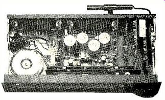
------------- Most of the circuits of the Audio Pro TA-150 are mounted on vertical printed circuit boards plugged into a master board carrying the interconnections and power-supply circuitry.
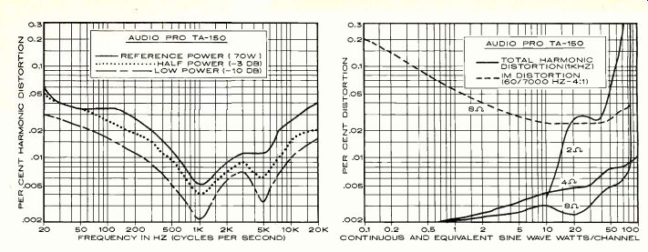
-------------- FREQUENCY IN HZ (CYCLES PER SECOND) CONTINUOUS AND EQUIVALENT SINE WAVE WATTS/CHANNEL
The balance control does not even exist as a physical entity. Channel balance is varied by having the computer differentially shift the signal attenuators for the two channels. Similarly, the loudness control has no separate components; it merely instructs the computer how to set the filter responses to obtain the desired results.
There is obviously much more to this receiver than can even be touched upon in the available space. One thing worth mentioning, however, is its mechanical construction. It is assembled on a number of individual printed circuit boards, or cards, which plug directly into a large "mother" board. Except for the power-line input, there is virtually no discrete wiring in the set, all interconnections being part of the printed wiring. The cards include the left- and right-channel power amplifiers (whose heat sinks screw to the case), the tape-input card, phono- and aux-input card, FM-tuner card, AM-tuner card, preamplifier card (including the volume and tone-control functions), microprocessor card, and the front card that carries all the pushbuttons and displays. Each card is separately tested and aligned and can be replaced in a moment without tools and with no need for any adjustment or alignment of it or any other part of the receiver. All related input and output connectors are part of the cards themselves (accessible through holes on the rear of the cabinet where required), so that the entire performance of any module can be guaranteed when a new module is plugged into the receiver.
Finally, the single knob is quite unlike any ordinary control knob. For one thing, it does not turn anything! It is on a short shaft, with a large number of detents to give it a "feel" and sense of location as it is turned. On the back of the knob are 128 alternating light and dark segments illuminated by an infrared LED and scanned by two phototransistors in the receiver. When the knob is turned, the optical sensing system sends impulses to the computer that tell it how far the knob was turned and in which direction. Depending on the selected function, these impulses then direct the computer to take the necessary action (change frequency, volume, etc).
The microprocessor continuously scans all the inputs and indicating devices, approximately 1,000 times per second, lighting the appropriate indicators each time and comparing the input signals to the previous ones to detect any change. When a button is pressed, the computer notes the fact but does not act on it immediately (since the impulse might be noise from a stray electrical transient). After two more checks, if the contact appears to be genuine, the computer switches to a sub-routine to execute the command. The assigned change is made, and the system returns to its scanning. Since the entire process takes only a small fraction of a second, it appears to the user to be instantaneous.
DIN sockets are used for the signal inputs, speaker outputs, and antenna connectors on the rear apron of the receiver. Adaptors are furnished to convert all of them to the phono connectors used in this country. In addition to the TAPE, PHONO, and AUX connectors, there is a PREAMP OUT/POWER AMP IN socket. Plugging a DIN plug into this disconnects the junction between the two sections of the amplifier. Pushbuttons on the rear of the receiver activate the two sets of speaker out puts. There are a hinged AM ferrite-rod antenna and a single switched a.c. outlet on the rear apron. The Audio Pro TA-150 is finished in black throughout, with white markings. It is 19 1/2 inches wide, 10 1/4 inches deep, and 2 1/2 inches high; it weighs 25 pounds. An optional ...
------R.F. TEST-SIGNAL INPUT IN DBF
... wooden cabinet is available. The same receiver, less power amplifiers, is available as the TPA-150 tuner/preamplifier. The suggested retail price of the Audio Pro TA-150 is $1,135. The TPA-150 is $995. The wood cabinets are $40 to $65, depending on the finish.
Laboratory Measurements. The one-hour preconditioning period, with the amplifiers delivering 23 watts to 8-ohm loads, left the top and back of the Audio Pro TA-150 very hot (too hot to touch for more than a second or two). However, even after the extensive testing that followed, there was no further heating or apparent degradation of any performance characteristic. In normal operation, the receiver became only moderately warm.
With both channels driving 8-ohm loads at 1,000 Hz, the clipping headroom was 0.72 dB (82.6 watts). With 4-ohm loads, the outputs clipped at 120 watts for a 1.25-dB clipping headroom rating. Into 2-ohm loads (for which the receiver is not rated) the outputs clipped at 94 watts. The dynamic headroom (clipping power during a 20-millisecond burst signal) was 1.77 dB (105 watts) with 8-ohm loads and a large 3 dB (180 watts) into 4 ohms.
The harmonic distortion at 1,000 Hz was barely detectable at most power levels, being under 0.003 percent from 0.1 to 30 watts output, 0.005 percent at the rated 70 watts, and 0.007 percent at 82 watts, just before clipping occurred. Into 4-ohm loads, the distortion was only slightly higher, rising from less than 0.003 percent in the under- 1-watt range to 0.005 percent at 30 watts and eventually to 0.013 percent at 110 watts, just un der the clipping point. Even 2-ohm loads did not severely affect the amplifier's distortion at normal listening levels. It measured 0.004 percent at 10 watts, less than 0.03 percent up to 40 watts, and 1 percent at 90 watts. The 8-ohm intermodulation distortion (IM) was in the 0.02 to 0.03 percent range at most power levels up to about 60 watts, and only 0.036 percent at 80 watts. Across the audio-frequency range, the distortion at the rated 70-watt output dropped from about 0.05 percent at 20 Hz to 0.005 percent at 1,000 Hz and then rose to 0.04 percent at 20,000 Hz.
At reduced power levels the shape of the distortion curve was similar but the measured values were lower.
To drive the amplifier to a reference output of 1 watt, an Aux input of 21 millivolts (mV) or a PHONO input of 0.28 mV was needed. The respective A-weighted signal-to-noise ratios were 73.5 and 71.5 dB, referred to 1 watt.
The phono preamplifier overloaded at 175 mV at 1,000 Hz and at equivalent levels at 20 and 20,000 Hz. The RIAA phono equalization was accurate within +0,-1 dB from 20 to 20,000 Hz referred to the 1,000-Hz level, and it was not affected detectably by the presence of phono-cartridge inductance at the in put to the preamplifier. The phono input had a resistance of 50,000 ohms, shunted by 100 picofarads (there is space on the phono card to add capacitance if the cartridge requires a higher value). The amplifier slew factor was greater than our measurement limit of 25 (according to the manufacturer, the amplifier response extends to beyond 500 kHz, but it is rolled off ahead of the power amplifier to pre vent interference from AM broadcasts and any chance of slew-related distortion).
The tone controls had the specified characteristics, but the shape of their curves was un like any we have seen in the past. Both the bass and treble control responses are hinged at 850 Hz, with shelved boost characteristics and a slight additional dip in the response at 80 and 10,000 Hz when full cut was used. The midrange control affected a wide range of frequencies in boost but only 'a rather narrow band centered at 850 Hz in cut (this is to be expected from the basic design of the tone-control system and the response curves of the bass and treble sections).
The loudness contours boosted only the low frequencies, with the same shelved response we noted in the tone-control curves (since it uses the same filter algorithm). The boost was not apparent until the volume had been reduced about 30 dB from maximum. The Low and HIGH filters had gradual 6-dB-per-octave slopes, with-3-dB points at 40 and 8,000 Hz.
The amplifier also has a fixed infrasonic filter operating below 14 Hz.
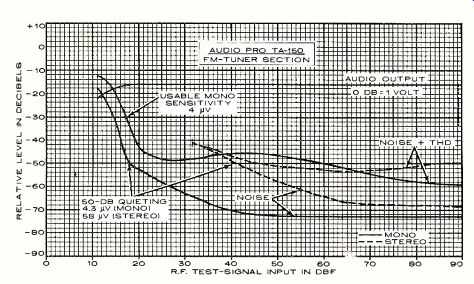
The FM tuner's usable sensitivity of 17 dBf (4 microvolts) was lower than we usually measure on medium- and high-price receivers, but quite adequate for most situations.
The 50-dB quieting sensitivity was 17.8 dBf (4.3 uV) in mono, with 1.8 percent total harmonic distortion (THD), and the stereo sensitivity was 40.5 dBf (58 uV) with 0.4 percent THD. At a 65-dBf (1,000 u V) input the distortion was 0.23 percent in mono and 0.21 percent in stereo, and the respective signal to-noise measurements at that level were 73 and 67 dB. These measurements were made at the tape-recording outputs as usual, but we found that, as with some other European-made receivers, the output-signal voltage to a tape deck was much lower than we usually measure: about 140 mV (0.14 volt) from a 100 percent modulated FM signal.
The FM frequency response showed some rolloff at the high frequencies, to almost-7 dB at 15,000 Hz. The channel separation was about 40 dB in the midrange, 32 dB at 30 Hz, and 15 dB at 15,000 Hz. The tuner's capture ratio was exceptionally good: 0.77 to 0.87 dB depending on the signal level. AM rejection was fair at about 50 dB and image rejection was an acceptable 61 dB. The tuner's selectivity was good: 80 dB for alternate-channel spacing and 6 dB on adjacent channels. The muting threshold was 17 to 20 dBf (4 to 5 V), with the muting and un-muting action taking place smoothly over that range of signal levels. The stereo switching threshold was 22 to 30 dBf (7 to 16 u V). The level of the 19-kHz pilot carrier in the audio was-66 dB, and the tuner's hum was-67 dB. Our only measurement on the AM tuner was of its frequency response, which was considerably flatter than most we have seen, though not really much wider. The response was almost perfectly flat from 100 to 3.000 Hz and was down 6 dB at 22 and 4,500 Hz.
Comment. The Audio Pro TA-150 is a curious combination of a rather ordinary tuner section, an extremely good audio section, and a most remarkable control system. One small flaw in its operation is in the AM tuning (and this is very minor for me, since I do not ordinarily listen to AM). The "stepped" knob action has the effect of tuning the AM section in small discrete increments, and it is usually not possible to set it exactly to the frequency of a desired station. It is frustrating to hear the obvious sound of a mistuned AM receiver-and then to move the knob one notch only to hear the tuner pass through the signal and come out the other side! The receiver should really have AFC for its AM tuner or else leave out the AM band entirely.
To us, the total worth of a product such as this is heavily influenced by its less tangible aspects (or at least its less audible ones).
Apart from the undeniable novelty of the TA-150's computer control system, it has also done away with almost every part that might wear out or require service. By eliminating switches, potentiometers, tuning capacitors, dial cables, and virtually all the point-to-point wiring, it seems reasonable that the designers of the TA-150 have extended its potential trouble-free life by a significant amount.
Assuming that the TA-150 continues to work indefinitely (as well it may), does it still offer any advantages over a conventional receiver? I think so. Frankly, from what I had read of the single-knob control of this receiver, I had prejudged that feature as a "gimmick." I was very wrong. Within minutes after setting up the receiver, I found that using it was an almost automatic process. Unlike most similar components, there was no need to remember control locations or search among a large number of seemingly identical knobs for the specific control needed. Practically no familiarization time is necessary with the TA-150. There is only one control, and the indicator lights next to it leave no doubt as to what it is controlling. The overall "feel" of the receiver is outstanding. In our view, the Audio Pro TA-ISO is the most successfully "human engineered" high-fidelity product we have ever seen, and we would be happy to see its design philosophy in other components.
Yes, it is expensive, and no, it really doesn't sound any better most of the time than some receivers selling for a fraction of its price.
Still, it handles so perfectly and is so free of apparent flaws (with the minor exceptions noted) that I think I could be happier with it than with some comparably priced receiver with a couple of dozen knobs.
There are many other features of the TA-150 that are worth commenting on, but space does not permit any more. Summarizing, it is a superbly sophisticated product, a genuine computer-age receiver, and without a doubt the simplest to operate that we have yet seen. Its FM-tuner section is at least competent, and its audio performance is outstanding. All things considered, the price seems quite reasonable.
Also see:
EQUALIZERS -- They are much more than just a fancier set of tone controls, DONALD SHEFFIELD
Source: Stereo Review (USA magazine)