Fig. 4-1. This arrangement can be designed to generate frequencies from 250 mhz to 2500 mhz. The tuned circuits consist of three coaxial cylindrical conductors.
| Home | Audio mag. | Stereo Review mag. | High Fidelity mag. | AE/AA mag. |
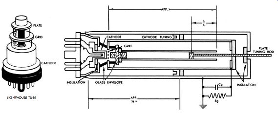
We know that ordinary coils and capacitors are not well suited to use in circuits that operate at frequencies above 250 mhz. Hence, oscillators in uhf signal generators have constructions as shown in Fig. 4-1. Typical uhf-oscillator arrangement.
Fig. 4-1. This arrangement can be designed to generate frequencies from 250
mhz to 2500 mhz. The tuned circuits consist of three coaxial cylindrical conductors.
The inner cylinder is connected to the plate of the oscillator tube. It is analogous to the plate coil in a conventional oscillator circuit. The next cylinder is connected to the grid of the tube ; it is analogous to the grid coil in lumped-circuit oscillators. The outer cylinder is connected to the metal shell of the tube and is the ground-reference point. Note that the cathode is capacitively coupled via the insulation ring to the grounded cylinder ; hence, the cathode is at r-f ground potential .
OSCILLATOR TUNING
The space between the cathode and grid cylinders forms a coaxial cathode line which is shorted at the far end by the cathode tuning plunger. Note that the plunger does not actually contact the grid cylinder ; this would produce a d-c connection from grid to cathode and short-circuit the grid bias.
However, the capacitance between the plunger and the grid cylinder is large enough to be an effective r-f short circuit.
Signal-developed bias is used in the oscillator circuit, and is produced by current flow through the grid-leak resistance Rg• Next, consider the plate circuit. This consists of a coaxial line comprising the grid and plate cylinders. The line is an open circuit at the far end. D-c plate voltage is applied via the plate-tuning rod at the point where the plunger contacts the plate cylinder. With respect to the oscillating frequency, this contact point is l,4-wavelength from the far end of the plate cylinder, as indicated in Fig. 4-1. This quarter-wave section, which is shorted at the point where B + voltage is applied, presents a high impedance to r-f from the open-ended plate line. Thus, it operates as an r-f choke and prevents r-f energy from flowing into the power supply.
We find that the tuning of the plate line determines the resonant frequency and is the chief control of oscillator frequency. It has a secondary effect on feedback. The cathode line is the primary feedback adjustment, and it is usually adjusted for maximum output. However, there is some inter-action between the plate line and the cathode line. Hence, to adjust the oscillator for maximum output at a given frequency, the plate and cathode plungers must be adjusted back and forth to find the optimum operating condition.
EQUIVALENT CIRCUITS
To clearly understand the oscillator action in Fig. 4-1, note the equivalent circuits depicted in Fig. 4-2. In Fig. 4-2A, coils Lk and 4 represent the inductances of the shorted cathode line and the open-circuited plate line, respectively. This is a true representation of the actual circuit? provided that the cathode line is less than 3,4 wavelength long? and provided that the plate line is less than a full wavelength long. The arrangement in Fig. 4-1 is based upon 3,4 wavelength and full wavelength, although operation is possible using 1,4 and 112 wavelengths. The reason for this choice is that at high uhf frequencies, 1,4 and lj2 become inconveniently short from a mechanical standpoint.
However, keep in mind that if the cathode line is slightly less than 1,4 wavelength, it acts like an inductance, and if the plate line is slightly less than 112 wavelength, it will act as an ...
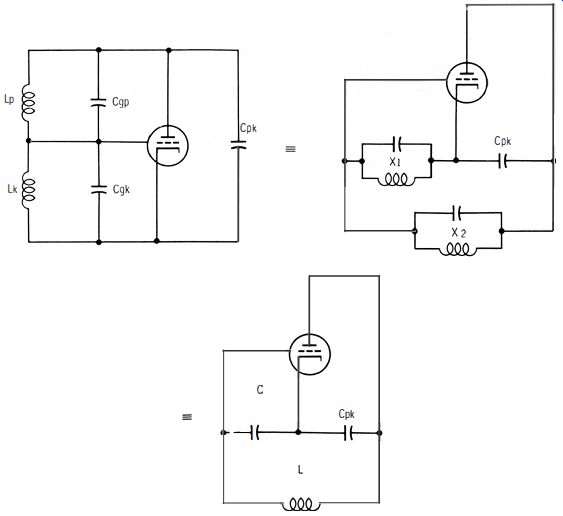
Fig. 4-2. Equivalent circuits for Fig. 4-1 .
... inductance. Note that no lead inductance is indicated in Fig. 4-2A because the coaxial lines connect directly to the tube electrodes. The interelectrode capacitances of the tube complete the equivalent circuit.
Next, consider the equivalent circuit in Fig. 4-2B. The parallel combination of Lp and Cgp is represented by X2. Similarly, the parallel combination of Lk and Cgk is represented by X1 Evidently, the reactances X2 and X1 along with Cpk, will form a resonant circuit. The reactance X1 acts as a voltage-divider circuit with respect to Cgk• Since the voltage across X1 is the voltage fed back to the grid, it must be 180-degr. out of phase with the plate voltage to produce oscillation. This 180-degr. phase difference can exist only if X1 is a capacitive reactance. This consideration leads to the equivalent circuit in Fig. 4-2C, in which the reactance X1 is now represented by a capacitor.
Any oscillatory circuit requires at least one inductance.
Therefore, X2 must be an inductive reactance. Accordingly, in Fig. 4-2C, reactance X2 is represented as an inductance L. We can understand that Fig. 4-2C represents the arrangement of Fig. 4-1 only at its resonant frequency. The circuit of Fig. 4-2C is recognized as a Colpitts oscillator. Now, if Xl is capacitive, Cgk must conduct more heavily than Lk• In other words, this is simply the circuit action which defines Xl as a capacitive reactance. Therefore, the oscillator frequency must be higher than the resonant frequency of :4 and Cgk• Again, for X2 to be inductive, the oscillating frequency must be lower than the resonant frequency of Lp and Cgp
To put it another way, the feedback condition for oscillation requires that the oscillating frequency occur between the resonant frequencies of the plate circuit and the cathode circuit.
FEEDBACK CONSIDERATIONS
In the arrangement of Fig. 4-2C, the amount of feedback depends on the ratio of C to Cgk• This, in turn, depends on the tuning of the cathode line in Fig. 4-1. This is the reason that feedback is controlled principally by the cathode tuning plunger. If too little feedback is used, the output from the signal generator will be weak, or may stop completely. On the other hand, if too much feedback is used, the grid circuit consumes excessive power and "robs" the available output. Since C and Cpk are in series (Fig. 4-2C) , and because C is usually much larger than Cpk, it is necessary to change C quite a bit to greatly affect the oscillating frequency. Hence, the position of the cathode tuning plunger in Fig. 4-1 has only a secondary effect on the frequency of oscillation.
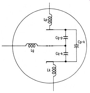
Fig. 4-3. Lead inductance and inter-electrode capacitance in a triode tube.
PLATE-TUNING CONSIDERATIONS
Since the position of the plate tuning plunger in Fig. 4-1 determines the resonant frequency of the plate circuit, which in turn establishes the amount of inductance present in the plate circuit at the oscillating frequency (Fig. 4-2C) , it follows that the plate tuning is the chief control of frequency.
Note that if an ordinary triode were used, the oscillator would be inoperative. Tube-construction features that limit high-frequency oscillation are interelectrode capacitances, lead inductances, and transit time (Fig. 4-3) . At low frequencies, such as 1 mhz, the interelectrode capacitances in an ordinary tube have reactances which are high enough to avoid difficulties in circuit action. However, when an oscillator is operated at a sufficiently high frequency, the reactance of an inter-electrode capacitance becomes of concern.
For example, a 1-pf capacitor has a reactance of 1590 ohms at 100 mhz. If this capacitor is the interelectrode capacitance between the grid and plate of a tube and the r-f voltage between grid and plate is 250 volts, there will be an interlectrode capacitance current flow of 0.157 ampere in accordance with Ohm's law. This heavy r-f current flow will seriously disturb circuit action. On the other hand, at 1 mhz the reactance of this capacitance becomes approximately 159,000 ohms, and the r-f current flow is only 0.00157 ampere. This small current flow does not seriously disturb circuit action.
A good point to remember is that the higher the frequency, or the greater the interelectrode capacitance, the greater is the current flow through this capacitance. In most uhf oscillators, interelectrode-capacitance currents are much greater than the output supplied by the oscillator.
EFFECT ON FREQUENCY
The tuned-plate tuned-grid oscillator configuration in Fig. 4-4 can be regarded as the equivalent circuit for the resonant line arrangement used in some uhf signal generators. Since the interelectrode capacitances are effectively in parallel with the tuned coils, they must affect the resonant frequencies. Note that the plate-to-cathode capacitance is in parallel with the series combination of plate-to-grid capacitance and grid-to cathode capacitance. All of these capacitances together form a part of the total capacitance of the tuned circuit. Evidently, the interelectrode capacitances establish the minimum capacitance attainable across the inductances. With a given minimum inductance, a high-frequency limit is imposed.
In addition, interelectrode capacitances have another undesirable aspect. The value of interelectrode capacitance is not fixed ; it varies with the applied voltages and with the loading of the oscillator. This results in oscillator-frequency instability.
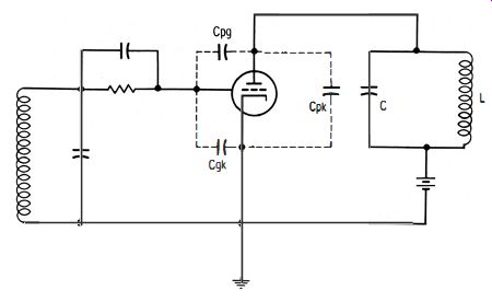
Fig. 4-4. Interelectrode capacitance affects frequency of oscillation.
Although the power supply may be regulated, slight changes in supply voltages will still be present. The oscillator is loaded by the attenuator in the signal generator, and some applications will draw more current than others from the attenuator.
In turn, the loading on the oscillator changes, and the frequency shifts. Therefore it is desirable to make the interelectrode capacitances only a small part of the total tuning capacitance. For this reason, uhf-oscillator tubes are designed to have the minimum interelectrode capacitance possible.
LEAD INDUCTANCE
Another frequency-limiting factor in a tube is the inductance of the leads to the tube elements (Fig. 4-3) . Although these inductances do not necessarily reduce the efficiency of the oscillator, they may nevertheless represent a major portion of the inductance in the tuned circuit. In turn. a high-frequency limit is imposed because the total inductance cannot be made small enough. Furthermore, since the cathode lead is common to both plate and grid circuits, lead inductance causes negative feedback, with a loss in oscillator efficiency.
TRANSIT TIME
A third limitation imposed by ordinary tube construction is transit time. This is the time required for electrons to travel from cathode to plate. At 1 me, for example, transit time can be disregarded, since it occupies a very small portion of one cycle. On the other hand, at a sufficiently high frequency, transit time occupies an appreciable portion of one cycle and impairs oscillator operation. The effect of transit time is of particular concern with regard to input impedance of the tube.
Part of the current which flows in the grid circuit is the current which charges Cgp in Fig. 4-4. The voltage which produces this current is the vector sum of the input voltage (grid to cathode) and the output voltage across the plate load.
At lower frequencies, with a resistive load these two voltages are 180 degr. out of phase and they add algebraically to determine the charging current. Since the input reactance is capacitive, this current is 900 out of phase with the input voltage. However, at higher frequencies where transit time is an important consideration, the plate current begins to lag the input voltage. This causes the plate voltage to be less than 180-degr. out of phase with the grid-input voltage, and the voltage across the input capacitance lags the input voltage. Accordingly, the charging current is no longer 900 out of phase ; it is partly in phase with the input voltage. This simply means that power is consumed in the grid circuit. It is equivalent to shunting a resistor between grid and cathode. At a certain limiting frequency, this resistance approaches a dead short circuit. Hence, tubes used as oscillators in uhf signal generators must have sufficiently fast transit time to permit reasonably efficient operation.
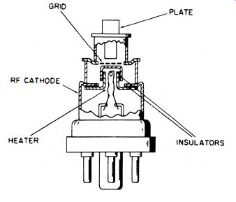
Fig. 4-5. Interior construction of a lighthouse tube.
UHF TUBES
Several methods are used to reduce the undesirable effects of interelectrode capacitance in uhf tubes. The lighthouse tube, depicted in Fig. 4-5, is typical of uhf tubes used in signal generators. No known method of coping with interelectrode capacitance is completely satisfactory. Capacitance can be reduced by spacing the electrodes farther apart. However, wide spacing introduces difficulty due to increased transit time.
Another approach is to reduce the size .of the tube and the electrodes. This is a satisfactory method, provided that the tube is not required to supply substantial output. Uhf-signal generators typically provide a maximum output power of 1 milliwatt.
Another way of reducing the total interelectrode capacitance is to reduce the lead capacitance by separating the leads widely, and bringing them through the tube envelope from their connection point directly to each electrode. Recall that it is also helpful to reduce the inductance of the leads. Short leads have minimum inductance. Two short leads connected in parallel have still less inductance. In the lighthouse tube construction (Fig. 4-1) , the leads are metal rings or disks that have unusually low inductance.
To reduce transit time, electrodes are spaced close together ; however, this increases the interelectrode capacitance. Another approach is to use a higher plate voltage to attract the electrons more rapidly from cathode to plate. There are practical limits to the plate voltage that may be applied. Hence, uhf tubes such as the lighthouse house type are necessarily a design compromise. Expert compromise has made it possible to use comparatively inexpensive tubes in the uhf range-a feat which was once considered impossible.
LIMITATIONS IN EXTERNAL CIRCUITS
As in any signal generator, the output from uhf oscillators must be passed through an attenuator and made available for external application. In the flow and control of uhf energy, we are basically concerned with power losses due to skin effect and radiation. Skin effect causes a considerable increase in the uhf resistance of a conductor. This results in high PR losses. To minimize skin-effect losses, the conductors in the generator are made large in size and tubular in shape. Since uhf current flows only on the surface of the conductor, its area is maximized. In addition, the conducting surfaces are plated with silver, since silver has a higher conductivity than copper. The next problem is controlling uhf radiation in the signal generator.
Why do ordinary circuit configurations radiate? It is because of incomplete cancellation of electromagnetic fields in the region surrounding the circuit. When the frequency is low enough that the spacing between two parallel conductors equals only a very small fraction of a half wavelength, there is almost complete cancellation of fields in all directions. At higher frequencies, however, the same spacing represents a larger fraction of a half wavelength. In turn, there is less cancellation of electromagnetic fields. In extreme cases, as when the spacing is a half wavelength, the fields will add in the direction of the plane of the two conductors. This causes the tuned circuits to radiate energy like an antenna.
Therefore, as the frequency is increased, it is necessary to reduce the spacing between the parallel conductors. However, there is a limit to how far you can go in reduction of spacing.
Too close spacing would provide uncertain insulation for the operating voltages. Hence, at uhf, radiation is minimized by use of concentric lines instead of ordinary conducting leads.
The outer cylinder of the line acts like a shield which prevents escape of uhf energy from its path of flow.
KLYSTRON OSCILLATOR
Signal generators which operate in the range from 2500 to 7500 mhz commonly use Klystron oscillators. Fig. 4-6 shows the construction of a typical Klystron type of uhf tube. Operating voltages are noted in the circuit diagram of Fig. 4-7.
The output from the oscillator is coupled into a hairpin loop and conducted to the attenuator via a coaxial cable. The cathode emits electrons which are attracted by the positive cavity grids. This positive voltage is equal to Ea, which may be about 500 volts. Observe that the control grid is placed between the cathode and the cavity grids ; the grid is positively biased to 200 or 300 volts, and it controls electron flow.
Electrons emitted from the cathode travel toward the cavity grids at a velocity determined chiefly by Ea. Most of the electrons pass through the control grid, through the cavity grids, and continue toward the repeller plate. After passing the cavity grid, the electrons arrive at a region where the electric field opposes their motion, because the repeller plate is negative with respect to the cathode by voltage Er•
This voltage is approximately -100 volts. In turn, the net voltage between repeller and cavity grids is in the order of 400 volts. The electrons slow down, come to a stop, and then reverse their travel to pass again through the cavity grids. Finally, the electrons are collected either by the control grid, the shell, or the cathode of the Klystron.
An important consideration here is the cause of oscillation in the resonant cavity between the cavity grids. In most oscillators, oscillations start from some irregularity in current
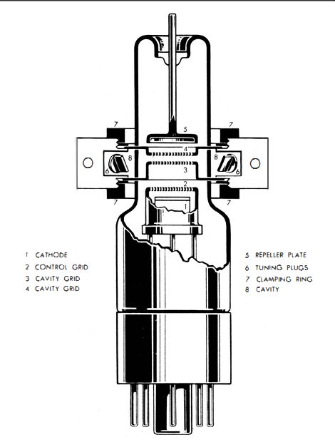
Fig. 4-6. Klystron type of uhf-oscillator tube.
flow, such as a transient which results from voltage being suddenly applied to the tube, or the starting transient may be due to shot effect. With this fact in mind, assume that oscillation of the electromagnetic field in the cavity is already taking place. From this assumption, let us examine the source of energy needed to sustain this electromagnetic field oscillation.
With the tank circuit (cavity) oscillating, a high-frequency voltage (denoted as e in Fig. 4-7) appears between the two cavity grids. This makes the electric field between the two grids reverse twice during each complete cycle of oscillation.
As the electrons approach these grids, the electron ' stream is uniform. The time that is required for the electrons to pass through the small distance between the grids is short compared to the period of oscillation. Electrons that enter the space between the grids when e is zero will encounter no electric field and will pass on through with the same velocity.
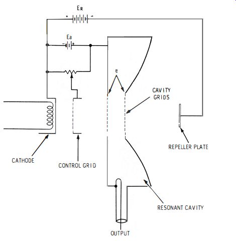
Fig. 4-7. Klystron oscillator circuit.
On the other hand, electrons that enter the space when e makes the left grid negative with respect to the right grid "see" a force field which tends to accelerate the electrons.
The amount by which they are speeded up depends on the value of e.
Again, electrons that enter the space when e is reversed in polarity are slowed down. These accelerations and decelerations are small in comparison with the original speed of the electrons. Those electrons which are speeded up most will travel farther toward the repeller plate before being turned back. Conversely, electrons which are slowed down most will be turned back before traveling as far. We see that the electron stream is no longer uniform. With the proper values of e, Ea, and Er in Fig. 4-7, electrons returning to the cavity grids will arrive in "bunches."
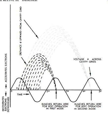
Fig. 4-8. Electrode bunching in a Klystron tube.
The diagram in Fig. 4-8 shows the position of electrons in the Klystron at various times during their transit. The zero distance position is midway between the cavity grids. Electron A, which arrives when e is positive, is accelerated and travels farther before being turned back. Electron B is unaffected.
Electron C is decelerated and turns back after a shorter excursion. Hence, in the diagram these electrons and those passing through at intermediate times are shown arriving back at the grids at the same instant. This is, the ideal situation, but it is not difficult to see that electrons will return to these gl"lids in a stream which varies in intensity at the frequency of oscillation.
On the return trip, the electric fields set up by voltage e again act on the electrons. Since they are now traveling in the opposite direction, they will be decelerated if they return
when e is positive, and they will be accelerated when e is negative. If an electron is accelerated, we know that its kinetic energy is increased. This energy increase is taken from the electric field. On the other hand, an electron which is decelerated gives up energy to the electric field. Clearly, if the bunches of electrons can be made to arrive back at the grid when e is positive, they will give up energy to the alternating field. For maximum transfer of energy, the bunches must arrive when e is at its positive maximum.
The question arises as to where this energy originated.
You have seen that if the electron stream from the cathode is uniform, some electrons are accelerated and some are decelerated on the outbound path. On the average, there are as many electrons absorbing energy from the field as there are those that give up energy to it. Hence, very little net energy is taken from the oscillating circuit during the bunching process. The average kinetic energy of the electron is that which is given to it by d-c voltage Ea in Fig. 4-7. Thus we see that energy is taken from the d-c electric field and given up to the AC field to sustain uhf oscillation in the Klystron.
ELECTRICAL TUNING
Cavity size determines the basic frequency of oscillation in a Klystron tube. Thus, the oscillator can be tuned by a mechanical means that varies the cavity volume. In addition, a Klystron can be tuned electrically. We perceive that it is not necessary for the bunches of electrons to return to the grids on the first positive swing of e after the first passage. Fig. 4-8 depicts bunches of electrons which also arrive on the second positive swing. However, the net result is the same. We see that the time in transit for the average electron B is 3,4 cycle, 1 %. cycle, 23). cycle, etc., and in actual practice there are three or four "modes" in which it is possible for the Klystron tube to oscillate.
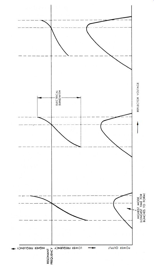
Fig. 4-9. Frequency and power-output variation VI repeller voltage, for thr
.. modes.
---------- TABLE 4-1.
KLYSTRON TYPE TUBES CHARACTERISTICS OF FOUR
The dark lines in Fig. 4-8 indicate paths of electrons operating in the first mode, while the light lines indicate paths of electrons operating in the second mode. A third mode is possible when the average transit time is 23 4 cycles, etc. Let us see how the transit time is controlled to produce oscillation in the different modes. Since the original velocity of an electron depends on the d-c voltage Ea in Fig. 4-7, and since the distance that the electron travels before turning back (and the speed with which it returns) depend upon the difference between Ea and Eo we find it possible to adjust the two voltages Ea and Er for any desired mode. The voltage Ea is usually fixed, since varying it produces greater initial velocity, which in turn causes a farther excursion and a greater return velocity. Hence, Er is made variable.
For operation in the first mode, the round trip must be completed in the shortest possible time. This occurs when the repeller plate is made highly negative. Next, if the repeller is made less negative, the transit time will be increased. Fig. 4-9 shows power output and frequency of oscillation plotted against repeller voltage for three modes of operation. Note that the frequency at the point of maximum output is the same for all three modes, and is the resonant frequency of the cavity in accordance with its mechanical dimensions. Note also that the power output for the different modes at the resonant frequency is least in the highest mode, and greatest in the lowest mode.
We find that power and amplitude limitations are due to over bunching as well as to the usual losses in the oscillatory circuit. Over-bunching occurs as follows : As oscillations build up and e becomes greater, the amount of acceleration and deceleration increases. This causes bunching to occur in a shorter period of time. Or, the bunching occurs before the electrons reach the grids on the return trip. This tends to reduce the magnitude of oscillation. In the higher modes of operation where the bunches are formed more slowly, the electrons are more susceptible to over-bunching. The magnitude of e which results in over-bunching, is lower, and oscillations are limited to a lower amplitude than in the lower modes of operation.
Thus, as shown in Fig. 4-9, the oscillating frequency in a Klystron is variable to a limited degree in any mode by varying the repeller voltage. When the repeller voltage is changed, it causes a bunch to return a little sooner or a little later than otherwise. Off resonance (mechanical resonance ), the amplitude of oscillation decreases by an amount that depends on the Q of the cavity. In the tube under discussion, the electrical tuning range is comparatively small and has its maximum range in the highest mode. Table 4-1 gives a comparison of four different types of Klystron tubes. The maximum electrical tuning range is provided by the 723A, which has an electrical bandwidth of 45 mhz.
ATTENUATORS
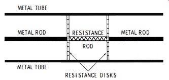
Fig. 4-10. Fixed attenuator section for a uhf generator.
Output from a uhf oscillator in a signal generator is taken via a coaxial line, as depicted in Fig. 4-7. Recall that open leads cannot be used because of excessive radiation and leakage. Hence, conventional attenuators cannot be used. Instead, uhf attenuators are built into coaxial lines. Fixed sections such as shown in Fig. 4-10 may be manually inserted or switched in series with the output coaxial line. This is a resistive pi section built into the coaxial line. Its advantage is that it maintains a fairly good characteristic impedance, which minimizes standing waves in the output system.
To form a variable attenuator, a metal tube that can be partially slid over the resistance rod is provided. This tube changes the value of the series resistance and in turn varies the PR loss in the rod. When a sliding metal tube is used, the resistance disks shown in Fig. 4-10 are usually omitted.
If several fixed attenuator sections are supplemented by a variable attenuator, the output from the uhf signal generator can be continuously controlled over as wide a range as desired.
Other forms of uhf attenuators that are based on principles of waveguides can be used. A waveguide is similar to a coaxial line that has no central conductor. In turn, the wave guide must have a certain diameter to conduct the uhf electromagnetic fields without attenuation. If the waveguide diameter is less than a critical value, it is said to be operating beyond cutoff. Attenuation of uhf energy is rapid when a waveguide is operated beyond cutoff. Thus, if a waveguide of ample dimensions is connected to a section which has a diameter less than the critical value, the narrow section operates as an attenuator. However, it is· more difficult to maintain a good standing-wave ratio with a waveguide attenuator than with a resistive coaxial attenuator, such as depicted in Fig. 4-10.
UHF SIGNAL GENERATOR MODULATION
Uhf oscillators can be modulated directly ; however, more difficulties are encountered than in the case of low-frequency oscillators. Hence, most uhf signal generators are externally modulated after the attenuator, and one or more semiconductor diodes are employed. Recall that a basic crystal-diode modulator is typically arranged as shown in Fig. 4-11. It is biased in the forward direction to a suitable operating point. Modulation occurs because the diode is a nonlinear resistance, and the modulating signal shifts the operating point up and down on the diode characteristic.
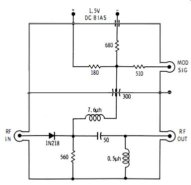
Fig. 4-11. Basic crystal-diode modulator.
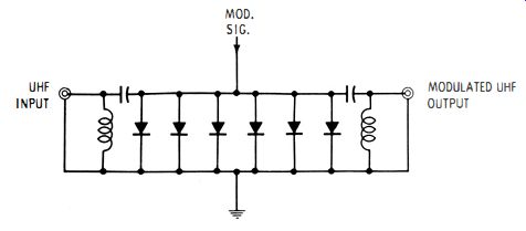
Fig. 4-12. Typical multiple-diode modulator.
In uhf application, the diode modulator must have coaxial construction. Moreover, the characteristic impedance of the modulator must be maintained as uniform as possible. This is done by utilizing a number of diodes, as seen in Fig. 4-12.
All the components in Fig. 4-12 are built into a coaxial line the ground is the outer conductor of the coaxial section. Uhf chokes are placed at each end of the modulator ; they act as a high-pass filter in combination with the small series capacitors. The filters prevent the modulating signal from flowing back into the generator, and they also prevent the modulating signal from flowing into the output cable from the modulator.
Why are several diodes used?
It is because each diode places a shunt loss across the line. This loss imposes reflections of uhf energy. However, if each diode places only a small shunt loss across the line, the standing-wave ratio is reduced. Consider a reflection from a diode at the center of the modulator--the reflected energy travels in both directions, but this energy is gradually absorbed by the other diodes. Hence, a minimum amount of reflected energy appears at the input and output ends of the modulator.
Furthermore, the diodes are selected to impose a graduated loss. In other words, the two diodes at the ends of the modulator are types which shunt comparatively little current across the line, while the two diodes at the center of the modulator are types which conduct much more current. Accordingly, most of the reflection occurs at the center of the modulator. The reflected energy from the center of the modulator is reduced to a satisfactorily low level by absorption in the other diodes. This type of modulator is used for either sine-wave or pulse modulation.