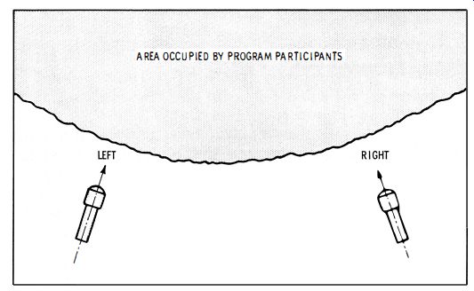
Fig. 5-1. Placement of stereo microphones.
| Home | Audio mag. | Stereo Review mag. | High Fidelity mag. | AE/AA mag. |
Basically, an fm stereo multiplex signal consists of two audio signals that occupy the same fm channel ; these audio signals provide stereophonic sound reproduction. The audio signals are identified as "Left" (L) , and "Right" (R) . These terms refer to the outputs from a pair of microphones at a sound studio, as seen in Fig. 5-1. The audio signal from the L microphone is slightly different from that of the R microphone. Again, the L and R signals may be the two outputs from a stereo record player. Sometimes the L and R channels carry unrelated audio signals, as exemplified by special sound effects. From the standpoint of signal generation, the basic fact is that a stereo signal consists of two audio waveforms which may vary independently in frequency and amplitude.
Fig. 5-1. Placement of stereo microphones.
At the receiver, the L and R signals are fed to separate speakers. The speakers are placed an appreciable distance apart, in correspondence to the distance between transmitting microphones, as shown in Fig. 5-2.
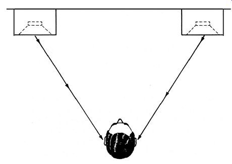
Fig. 5-2. Placement of stereo speakers.
FUNDAMENTALS OF STEREO MULTIPLEXING
Beginners might suppose that an fm radio channel could be divided into two equal parts for the transmission of the L and R signals on individual carrier waves. However, this over simplification is not feasible for two fundamental reasons.
First, consider the fact that one audio signal requires all the available bandwidth in an f-m channel. Fig. 5-3. Maximum frequency deviation in an '-m signal Is +75khz.
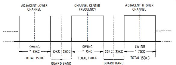
Fig. 5-3 shows the bandwidth relations ; each channel is flanked by a guard
band.
Although the center frequency of one channel is spaced 200 khz from the next, the guard bands reduce the available bandwidth of each channel to 150 khz. Or, the maximum available frequency swing in each f-m channel is +-75 khz.
This frequency swing of +-75kc is required for high-fidelity transmission of one audio signal. Why is this frequency swing required? It is because hi-fi reproduction comprises audio frequencies up to 15 khz. In an a-m signal this corresponds to a frequency spread of +- 15 khz, or a bandwidth of 30 khz. However, an f-m signal is different ; its sidebands have a greater spread. Since all the available bandwidth of an f-m channel is required to transmit a single audio signal, it is not feasible to cut this bandwidth in half in order to transmit a second audio signal in the same channel.
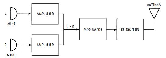
Fig. 5-4. Transmission of the audio signal for reception on an ordinary f-m
receiver.
Therefore, we must consider how two signals can be multiplexed so that each signal occupies all of the available bandwidth in the channel. The basic concept of multiplexing is that each signal shall be transmitted without distortion and without interference to the other signal . Furthermore, each signal must have an electrical characteristic which permits "clean" separation from the combined signal at the receiver.
Furthermore, there is a compatibility requirement. In other words, the L and R signals in Fig. 5-1 must be able to be reproduced as a single normal audio signal by a conventional f-m receiver. Or, the multiplex transmission must "look like" an ordinary f-m signal to a conventional receiver, but it must "look like" separable L and R signals to a stereo-multiplex receiver. These technical requirements might appear to be insurmountable ; however, the approved FCC method is comparatively simple. Let us analyze the system step by step.
It starts with the familiar monophonic (monaural ) audio signal, which is picked up by a single microphone. What is the relation between this mono signal and a pair of L and R stereo signals ? The mono signal is the arithmetic sum of the L and R signals. Hence, the first step is to employ two microphones as if they were one. If we mix the L and R signals as shown in Fig. 5-4, we obtain a mono signal. Then, if this L + R signal is modulated on the f-m carrier, the result is the same as if only one microphone were used.
Insofar as ordinary f-m receivers are concerned, only this monophonic audio signal is being transmitted. Actually, we shall see that additional information, to which an ordinary f-m receiver is unresponsive, is also being transmitted. The additional information is called a multiplexed signal. We sometimes say that the multiplexed signal is "encoded." This merely means that the encoded information is· ignored by a receiver unless special circuits are used to pick out and demodulate the encoded signal. Let us see what a multiplexed signal consists of.
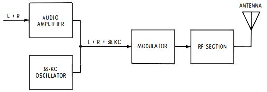
Fig. 5-5. The 38-khz signal is inaudible.
Suppose we add a 38-khz carrier to an audio program and modulate both signals on the rf carrier, as depicted in Fig. 5-5. Evidently, only the audio signal can be reproduced at the receiver. The 38-khz carrier is far out of the range of audibility.
Next, if we modulate the 38-khz carrier, this modulation will also be out of the range of audibility. If proof is needed, consider the following example. Even if we modulate the 38-khz carrier with a 15-khz audio signal, the lower sideband has a frequency of 23 khz, and the upper sideband has a frequency of 53 khz. Nobody can hear a 23-khz tone. Of course, this is 3 simplified example, because f-m sidebands occupy somewhat more channel space than a-m sidebands. Nevertheless, it illustrates the basic consideration.
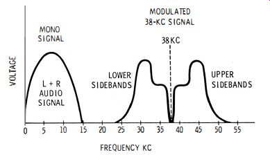
Fig. 5-6. Typical modulating signal that is applied to the r-f section.
For example, Fig. 5-6 depicts the output from an ordinary f-m receiver. The L+ R signal has frequencies from zero to 15 khz. This signal is the same as if a single microphone had been used at the studio. When modulation is applied to the 38-khz oscillator in Fig. 5-5, sidebands are produced, such as shown in Fig. 5-6. Thus, frequencies from 23 to 53 khz are also fed from the output of the f-m receiver to the speaker. Since the speaker cannot reproduce such high frequencies, and the ear could not respond to them in any case, it is just as if the 38-khz frequency and its sidebands were absent.
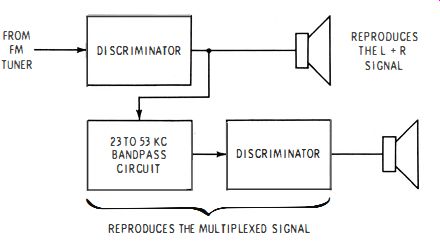
Fig. 5-7. A second discriminator makes the multiplexed signal audible.
Next, let us see how the upper and lower sidebands in Fig. 5-6 can be recovered and fed to another speaker. Fig. 5-7 shows the basic arrangement. The sidebands are picked out by the 23 to 53 khz bandpass circuit. In turn, this signal is fed to a second discriminator and is demodulated. Accordingly, the audio signal which modulated the 38-khz carrier is developed and is fed to the second speaker. The encoded signal, which was rejected by the first speaker, has been made audible from the second speaker. This is the fundamental principle of multiplex operation from transmitter to receiver.
FORMATION OF L AND R SIGNALS
Although the simple arrangement shown in Fig. 5-7 reproduces the two independent signals depicted in Fig. 5-6, it must be elaborated slightly to obtain an R signal from one speaker and an L signal from the other speaker and thereby meet the requirements for stereo reproduction. Let us see what is necessary. First, the upper speaker in Fig. 5-7 is reproducing an L + R signal. We need some easy way to cancel out the R signal, then the upper speaker will reproduce the L signal only. The way this is done is as follows. An L - R signal is modulated on the 38-khz carrier in Fig. 5-6.
Hence, the L - R signal becomes available at the output of the second discriminator in Fig. 5-7.
This gives us both L + R and L - R signals to work with.
If we add L + R to L - R, we get 2L. On the other hand, if we subtract L -R from L + R, we get 2R. Then, we can feed 2L to one speaker and 2R to the other speaker. This gives us stereo reproduction. You are probably saying, "This is all well and good, but how do we form the L - R signal in the first place ?" This is done with a phase inverter, as seen in Fig. 5-8. If we invert the polarity of the R signal and add it to the L signal, we obtain an L -R signal.
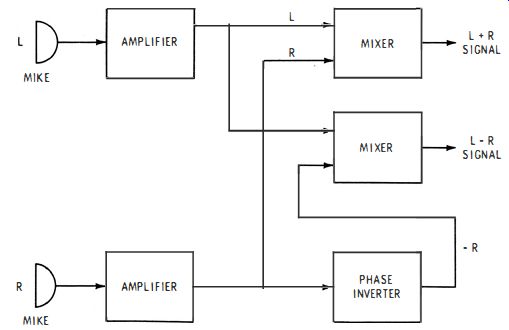
Fig. 5-8. Formation of L + R and L-R signals.
Now that we have the necessary L + R and L - R signals, it follows that the multiplex transmission is made as shown in Fig. 5-9. In turn, the upper and lower sidebands in Fig. 5-6 consist of the L - R signal . To obtain stereo reproduction at the receiver, we add and subtract the L + R and L - R signals in mixers, as seen in Fig. 5-10. Accordingly, one speaker reproduces the R signal, while the other speaker reproduces the L signal. Stereo reproduction thus results from multiplexing the L + R and the L - R signals when suitable receiving equipment is used.
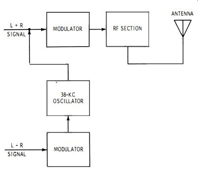
Fig. 5-9. How the L -R signal is multiplexed with the L + R signal.
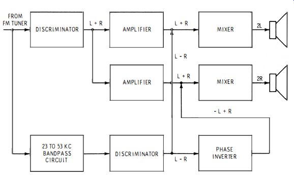
Fig. 5-10. Processing of the L + R and L-R signals to form L and R signals.
FM STEREO MULTIPLEX SIGNAL GENERATOR
It follows that an f-m stereo multiplex signal generator must be a miniature transmitter, as previously described. The generator supplies a choice of L + R or L -R signals. It also provides a combined L + R and L - R output. The generator usually provides additional test signals, which will be explained. (Refer back to Fig. 5-6) . We find that the 38-khz signal (technically termed the subcarrier ) could be transmitted but that it is actually suppressed in practice. The 38-khz subcarrier is suppressed to permit the upper and lower sidebands to be transmitted at a higher level than is otherwise possible. This improves the signal-to-noise ratio.
However, it is mandatory that the subcarrier frequency be reinserted with the sidebands at the receiver. If this were not done, the L - R signal would be highly distorted. Furthermore, the reinserted subcarrier must have correct frequency and phase. How can this be accomplished? The practical answer is to transmit a pilot subcarrier. This pilot subcarrier must be "in the clear" so that it is not interfered with.
Hence, the pilot carrier is set at 19 khz. It is seen in Fig. 5-6 that 19 khz falls in an empty space between the L+ R signal and the lower sidebands of the L -R signal. This insures clean reception of the pilot subcarrier without any interference.
At the transmitter, the 19-khz pilot oscillator is locked to the 38-khz subcarrier, which has been suppressed. Therefore, the second harmonic of the 19-khz pilot frequency is produced at the receiver, and it is used for reinsertion of the 38-khz subcarrier with the upper and lower sidebands of the L - R signal. This reinserted subcarrier is extremely accurate in both frequency and phase. Now, it is obvious that a stereo multiplex signal generator must supply a 19-khz pilot frequency, just as the transmitter does. This generator output is also useful for signal-tracing and signal-substitution tests, in addition to being required for normal receiver operation.
An f-m stereo multiplex generator also provides a 38-khz subcarrier signal. Although it is not used in tests of normal receiver operation, the 38-khz signal finds application in signal injection tests during alignment procedures. Of course, the generator must supply a modulated r-f signal . Hence, it also contains a modulated oscillator. The r-f oscillator operates at a typical frequency of 100 mhz. The L + R and L - R signals have a typical frequency of 1 khz. Since the generator provides a choice of individual basic signals that are steady and accurate, it permits the technician to pinpoint receiver troubles, and to adjust the receiver maintenance controls for optimum operation.
The available test signals are as follows :
1. Left monophonic output.
2. Right monophonic output.
3. Sidebands of L without 19-khz pilot.
4. Sidebands of - R without 19-khz pilot.
5. Sidebands of L with 19-khz pilot.
6. Sidebands of -R with 19-khz pilot.
7. L-channel composite signal without 19-khz pilot.
8. R-channel composite signal without 19-khz pilot.
9. L-channel complete composite signal .
10. R-channel complete composite signal.
11. 19-khz sine wave.
12. 38-khz sine wave.
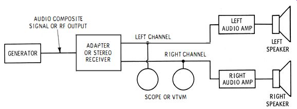
Fig. 5-11. A scope or vtvm accurately indicates the minimum output signal.
In other words, every signal component present in the receiver circuits can be obtained by switching the generator to build up a complete signal step by step. One of the more critical receiver adjustments concerns good separation of the L and R signals. With reference to Fig. 5-10, this means that minimum output should be obtained from the R speaker when an L signal is applied, and vice versa. These maintenance adjustments can be made only with the aid of a generator. It is quite helpful to use vtvm or scope indication of output voltage, as depicted in Fig. 5-11. Instrument indication is also the best means of determining the optimum setting of the balance control for equal response from each speaker.
GENERATOR CIRCUITRY
A block diagram of a typical f-m stereo multiplex generator is shown in Fig. 5-12, which is helpful in following the circuit diagram in Fig. 5-13. There are 11 functional units, as follows:
1. 1-khz audio oscillator.
2. Phase inverter.
3. 19-khz oscillator.
4. 19-khz-to-38-khz doubler.
5. AM modulator.
6. 38-khz carrier suppressor.
7. Audio composite adder.
8. Audio phase delay.
9. 67-khz oscillator.
10. Final amplifier and emitter follower.
11. R-f oscillator and f-m modulator.
Why is a 67-khz oscillator included ? It is because the FCC provides a subsidiary communications authority which may be used for transmission of background music. This is called SCA transmission, and it employs a 67-khz subcarrier located beyond the upper sideband limit in Fig. 5-6. Since an incorrectly adjusted receiver may be plagued with "birdies" when SCA transmission is used a 67 -khz check signal is desirable.
The internally generated 1-khz L and R signals are developed by a Colpitts-type oscillator which has a tuned 1-khz tank circuit (See Q1 in Fig. 5-13) . The L and R output signals that are fed to the base-emitter junction of Q2 have the same frequency and amplitude. To produce the L - R and L+ R signals, the output of the 1-khz oscillator (Q1) is applied to the base-emitter junction of Q2, the phase-inverter stage. The signal at the collector of Q2 is shifted 180 degrees in phase with respect to the input signal . Both the emitter and collector signals are fed to the audio switch (S1) . Note that the collector signal from the inverter stage is the - R signal ; the emitter signal from the inverter stage is the + R signal . Potentiometer R7 is called the L - R - R level adjustment.
It is a screwdriver control which permits setting of the - R signal amplitude. The signal at the emitter of Q1 is controlled by R8, which is the L + R level adjustment, and by R9, which is the L- R L adjustment. These are also screwdriver controls. Note that the L+ R level control (R8) determines the amplitude of the L + R signal , and the L - R L control (R9) determines the amplitude of the L- R signal . These are screwdriver controls.
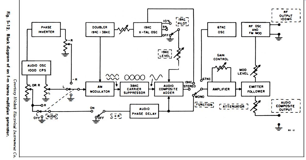
Fig. 5-12
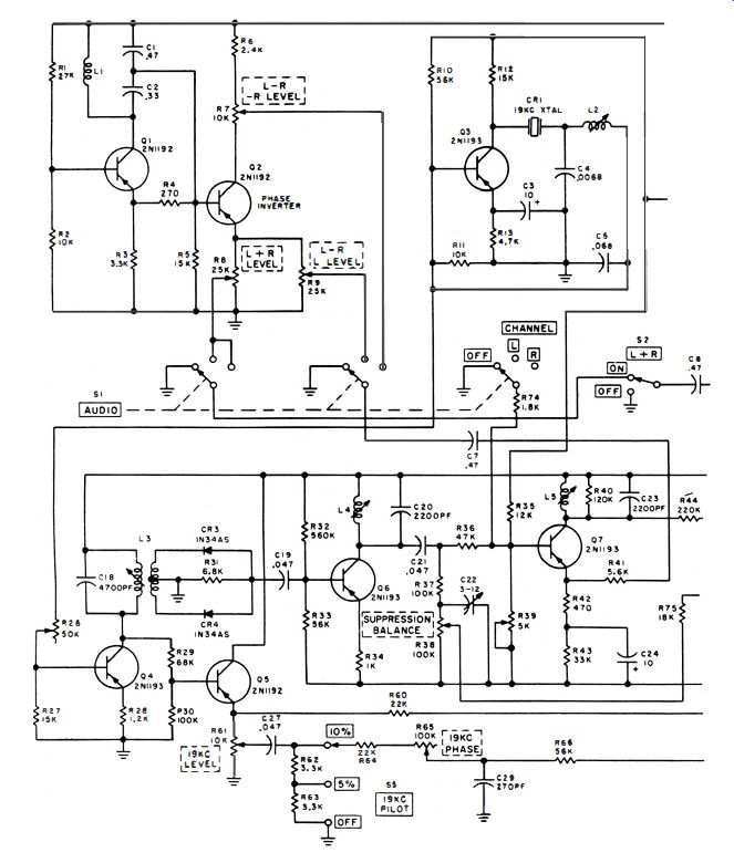
Fig. 5-13. Complete circuit diagram of an f-m stereo multiplex generator.
A 19-khz quartz crystal (CR1) is used to generate the pilot frequency. This is a highly stable signal source which is rated to an accuracy of +-2 cycles. The suppressed subcarrier, which has a frequency of 38 khz, is developed as the second harmonic of the pilot, and has a rated accuracy of +-4 cycles. Switch S5 provides a choice of 5% or 10% pilot amplitude, with respect to the total composite output. Its voltage is approximately 0.5 volt peak-to-peak. The amplitude of the audio composite signal is variable from 0 to 4 volts peak-to-peak. This audio composite output consists of an L or R 1-khz sine wave with sidebands of L or -R, and the double-frequency 19-khz pilot.
(See Fig. 5-14) .
(A) Complete composite signals for Land R channels.
(b) Distortion caused by 90° phase error of reinserted 38-khz subcarrier.
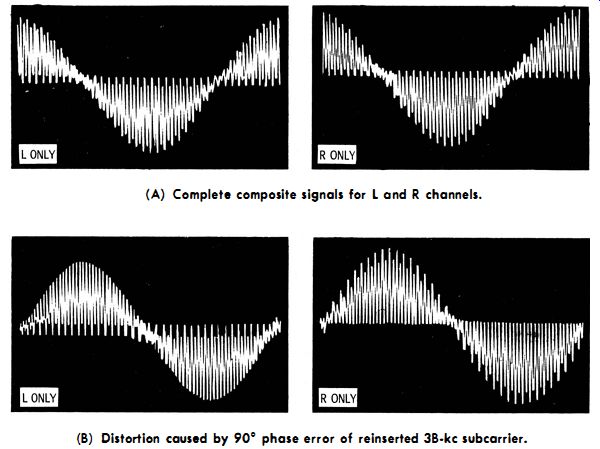
Fig. 5-14. FCC-Zenith standard waveforms showing the necessity for reinsertion
of the sub-carrier in the correct phase.
The monaural (mono) output signal is a 1-khz sine wave which has an amplitude of 1.8 volts peak-to-peak. Note that the 38-khz output signal is also a sine wave ; it has an amplitude of approximately 3 volts peak-to-peak. The 67-khz output is a sine wave that has an amplitude of at least 2 volts peak-to-peak. R-f output from J1 and J2 is approximately 500 microvolts. Channel separation provided by the generator is better than 35 db.
Maintenance of an f-m stereo multiplex generator that employs. transistors consists chiefly of an occasional touch-up of the gain control (R51 in Fig. 5-13) . Adjustment becomes necessary when the battery weakens. A scope is connected to the audio-composite output jacks J3 and J4. The scope must be calibrated for vertical sensitivity. If the peak-to-peak voltage of the signal is not within 5% 1 of 3.6 volts, gain control R51 is adjusted as required.
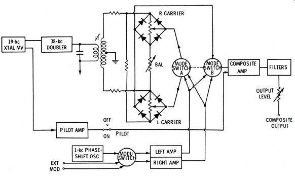
Fig. 5-15. Pair of bridge rectifier circuits form a balanced modulator.
STEREO SIGNAL GENERATION WITH BALANCED MODULATORS
Some stereo generators make use of balanced modulators.
A typical arrangement is shown in Fig. 5-15. The output from this generator cannot be fed into the front end of a stereo f-m receiver or tuner, but it can be applied directly to the input of a stereo adapter. In receivers that include stereo-multiplex circuits, the signal can be applied at the output of the second demodulator (usually a ratio detector). The key stage in Fig. 5-15 is the 19-khz oscillator, because all other circuit actions are controlled by the pilot signal generated "in this stage.
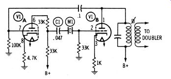
Fig. 5-16. Crystal-controlled 19-khz oscillator.
The 19-khz oscillator is a crystal-controlled multivibrator, as detailed in Fig. 5-16. It is a simple cross-coupled multivibrator, with one important addition ; the 19-khz crystal (M1) is part of the coupling capacitance, in combination with C1.
Because of the resonant frequency of , M1, only 19-khz . signal voltage can be coupled from V1A to V1B. In turn, the multivibrator can operate only at 19 khz. This 19-kilocycle frequency is the precise frequency of the pilot carrier in the stereo f-m signal.
With reference to Fig. 5-15, one portion of the 19-khz signal is fed to the 38-khz doubler, and another portion is fed to the 19-khz pilot amplifier. The signal from the doubler is coupled via a tuned balanced-secondary transformer, to a pair of bridge-rectifier circuits that operate as balanced modulators.
It is characteristic of balanced modulators that only sideband frequencies appear in the output. In other words, the carrier frequency is suppressed. Therefore, when audio or stereo signals, along with the 38-khz signal, are fed to the balanced modulator bridges, only the sideband frequencies appear in the output.
Note the sources of audio signal . A single 1000-hz signal, developed internally via a phase-shift oscillator, can provide (by means of the modulation switch) an in-phase signal for both channels, or a signal for the right channel that is 180-degr. out of phase with that in the left. The former combination is actually a monophonic signal, while the latter is a highly useful test signal for checking and comparing operation of the right and left channels in a receiver. As an alternative, a pair of inputs from an external source can be connected, via the modulation switch, as either a stereo or mono signal. Whatever the source or mode of audio signal, the output is fed to one corner of each balanced-modulator bridge.
The mode switch determines which audio-channel signal is received by either of the bridge circuits. With this arrangement, the mode switch can select a balanced-modulator output that contains sidebands of both L and R signals, sidebands of either L or R signals, or sidebands of a signal in which the right channel is 180-degr. out of phase with the left. In all cases, the 38-khz subcarrier is suppressed. The mode switch has two sections ; one section arranges the connections for the balanced modulator, and the other makes connections to the composite amplifier.
From the balanced modulators, the L - R sideband signals are fed to the composite amplifier where they are mixed with the direct L and R signals and with the pilot carrier. Additional filter networks help to remove any 38-khz subcarrier that might remain with the sideband signals. The composite stereo waveform is fed through a level control to the output terminal . Accuracy of phasing is easily checked with a scope, and any maintenance adjustments can be easily made on the basis of the composite stereo waveform.