Several different manufacturers offer remote controls for TV receivers.
This Section covers some of the more popular models.
DIRECT ACCESS REMOTE CONTROL (ZENITH 2000 SYSTEM)
This remote control system will be found in the Zenith color TV set L models. This direct access remote hand unit transmitter is a 16 button keyboard unit that is shown in Fig. 1. The functions include on, off, zoom, mute, volume higher and volume lower (continuous through 128 steps), plus channel entry buttons. The frequencies associated with the transmitter are given in Fig. 2. A block diagram of the 2000 remote control system will be found in Fig. 3.
Remote Hand Unit
The 124-14 hand unit transmitter is powered by a 9 volt battery. The 16 pin P-MOS digital IC is the heart of the transmitter. The IC senses any switch closures, scans the keyboard to determine which switch is closed, determines that the closure is valid, determines the X and Y coordinates of the closure, converts it to a 5 bit binary number which is used for gating internal counters to generate the desired ultrasonic frequencies. A simplified drawing of the hand transmitter is shown in Fig. 4. The output circuit is operated as a class C stage where pulses are applied to the tuned circuit of the ultrasonic speaker and output coil.
The best technique for testing a transmitter is to connect an oscilloscope to the microphone/preamplifier output. With the transmitter about one foot from the microphone, all buttons should provide a square wave signal which indicates the microphone/pre-amplifier is limiting the strong input signal.
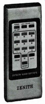
Fig. 1. Zenith 2000 remote transmitter.
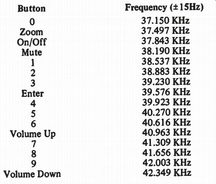
Fig. 2. Frequency chart for Zenith 2000 remote system.
---------
----------
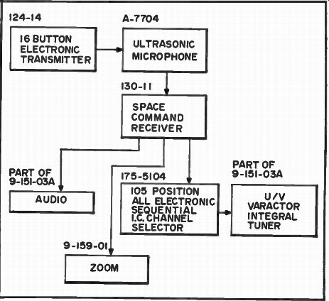
Fig. 3. Block diagram for Zenith 2000 remote system.
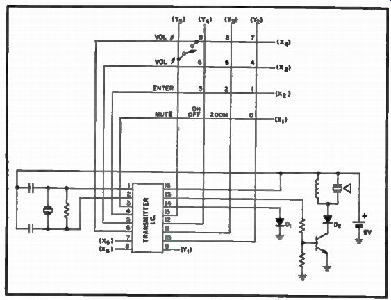
Fig. 4. Circuit for 124-14 hand unit.
Microphone Amplifier Unit
This portion of the remote system consists of an ultrasonic microphone and a three stage solid-state amplifier. The wider bandwidth requirements of the direct access system have been accomplished by minute changes in the size of the microphone bridge. There is a range control located on the back of the unit that should not be adjusted to a more sensitive level than the factory setting but may be adjusted to a less sensitive level. Good shielding is required and the original shield cover must be retained in place. The B+ is provided directly from the +12 volt position regulator Q201 located in the remote receiver module.
Remote Control Receiver (130-11)
The direct access receiver is made up of two digital integrated circuits and 12 discrete transistors. Power is supplied by two series voltage regulators, Q201, a +12 volt supply, and Q202 a - 6 volt supply.
Both supplies will provide 40 ma of current. Follow along with this circuit operation by referring to the block diagram of the remote receiver in Fig. 5.
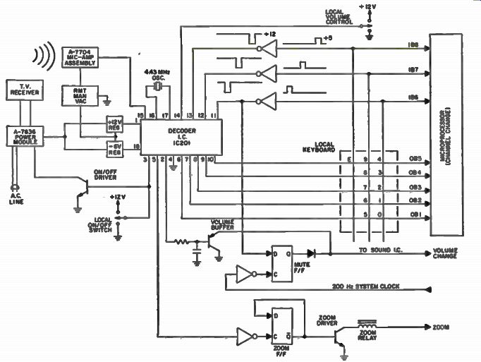
Fig. 5. Block diagram of Zenith 130-11 remote receiver.
The digital P-MOS chip, IC201, processes the received ultrasonic signal and provides direct channel selection by interfacing with a microprocessor. It also controls auxiliary functions such as on-off, volume, mute and zoom.
Since the IC uses a 12 volt supply and the microprocessor a 5 volt supply, level shifters Q203, Q204, Q205, convert positive-going 5 volt scanning pulses from the microprocessor to negative-going 12 volt pulses on pins 11, 12, and 13 of the decoder IC. A second IC, IC202, is a dual type C-MOS flip-flop. This is required as a memory storage bank for the mute and zoom functions. This allows continuous operation of the mute and zoom functions with only momentary depression of the buttons. The outputs available from the decoder IC are high only as long as these buttons are pushed. Hence, the need for storage in a flip-flop.
Transistors Q209 and Q210 are used as current amplifiers to increase the small current capability of the C-MOS flip-flop to that required to pull in the zoom relay.
Another level shifter, Q207, changes the 5 volt 200 Hz clock signal, from the microprocessor, into a 12 volt signal. This is required to gate the mute function into the mute flip-flop. Basically the microprocessor detects the mute function by scanning and then sends this function to be stored in the mute flip-flop.
Another inverter, Q208, is used to convert a negative-going transition occurring on pin 5 of the IC into a positive-going transition to clock in the zoom function.
A transistor, Q206, is used as a switch for activating a reed relay in the power module, which gates a Triac for turning the 1'V set on or oft.
This transistor can be changed from the off state to the on state either by remote control or manually by the local on-off switches.
The amplified ultrasonic signal from the microphone amplifier assembly is fed to the top end of R224, the trip point adjustment control.
This control is factory set, using a standard 200 millivolt RMS signal to compensate for differences in individual chip sensitivity. This control should not be adjusted without proper instruments.
More System Operation Notes:
Whenever an ultrasonic signal is fed into pin 15 of the IC201 (Fig. 6)
a long chain of events begins to take place. After an ultrasonic signal has been received by the chip it begins a measurement cycle. During the first 23 milliseconds, the chip ignores (does not count) the signal and it is basically inactive. This is to allow any room transients to decay. However, the measurement cycle taken during the first 23 milliseconds determines if the received signal has a period which is longer than the minimum requirement of 18 microseconds yet shorter than 36 microseconds the maximum value of a valid signal. If the ultrasonic signal duration is less than 23 milliseconds or the period does not fall within the above limits the chip will not respond. If the ultrasonic signal has a valid period and is longer than 23 milliseconds duration a channel counter counts the number of ultrasonic pulses occurring during the next (2nd) 23 ms period. This value is then transferred to a 5 bit latch and the channel counter counts pulses for another (3rd) 23 ms period. At the end of the second counting period (3rd 23 ms period) the contents of the channel counter are compared to the previous value stored in the 5 bit latch. If a comparison does not exist, then another measurement is made, followed by yet another measurement, if there is again no comparison. Thus, there are three opportunities to obtain a comparison between two consecutive measurements. This is recognized as a valid ultrasonic input and the ROM decoder is enabled and the appropriate output appears.
A check on the period of the ultrasonic signal is made continuously. If, at any time, an ultrasonic pulse is received which has a period less than 18 microseconds or greater than 36 microseconds then the check period logic produces a signal which resets all control and measurement logic and inhibits the output stages.
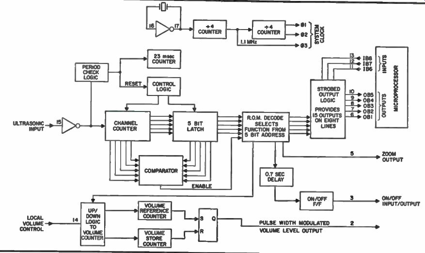
Fig. 6. Block diagram of IC 201 in remote receiver.
The zoom output, pin 5 of IC201, is simply a buffered decode from the ROM. The on/off output, pin 3, is toggled by the appropriate ROM output after a delay of 0.7 seconds. The on/off pin is bi-directional since it also acts as an input pin. The external switches force the on/off pin to a particular state, the change is sensed by the chip and that level is held when the input is removed.
The pin 2 volume out is a 8.7 kHz square wave output with a variable duty cycle. At power-up the duty cycle is essentially 50 percent. This output is filtered by an integrator and applied to the base of the volume buffer to control the TV volume level. The duty cycle is controlled by two free counters, a reference counter and a store counter. A volume up or volume down command increments the reference or store counter respectively so that there is a resultant change in the duty cycle of the output signal. In order to prevent blaring when the set is first turned on, a separate adjustment control, off emitter Q212 connector 11, (factory adjustment) is provided to compensate for any sound IF chip variations.
The manual volume input pin 14 of the IC201 is also tri -state (like the on/off) and the volume is changed by forcing the pin to +12 volts or ground.
In order to conserve pins on the IC, 15 possible outputs are read via 8 pins. This is accomplished by arranging the pins as three input and 5 output scan lines. Refer to Fig. 7. If, for example, the desired function is f5 (digit 5) then by scanning, it is possible to read f4, f5 and f6 on one line i.e., OB4. The microprocessor does this by sending pulses separated in time such as t1, t2 and t3. During t1 only the END gates activated by t1 could be read out, namely f3 and f6. During t2 functions f2 and f5 may be read out. In this case f5 is high and this is shown as a high only during the time t2 is high. Since the microprocessor keeps track of which pulse is being sent, it knows which function the remote has decoded. By this means the digits 0 through 9, enter and mute are detected. As mentioned, mute is returned to be stored at the mute Flip/Flop during the negative transition of the 200 Hz system clock.
Service Tips If set will not turn on check out the power supply module for the remote system. Check fuse, reed relay and Triac. Next, check for correct B+ voltages to the remote module. If set operates manually then see if the remote hand unit is transmitting the correct signals. If these checks are OK and the remote system seems dead check for the proper 200 Hz clock signal. Then suspect the microprocessor chip and the decoder IC, IC201.
MSC-003 FS SCAN REMOTE CONTROL (RCA)
The MSC-003 FS scan remote control module is used in the RCA CTC-93 color TV receivers. This unit works with the keyboard, remote receiver and preamp unit that makes up the total remote control system.
Control Module Symptoms No or improper channel Up/Down action.
No or improper ADD or ERASE of scan memory.
No or improper channel change or skip.
Preliminary Service Information Check all interface connections and wiring to and from the MSC control module. Each time the channel is changed note the display readout.
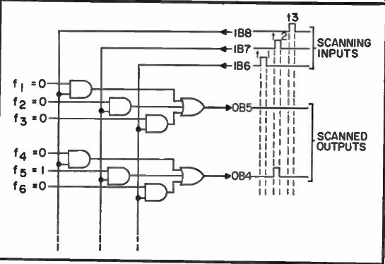
Fig. 7.Strobed output logic.
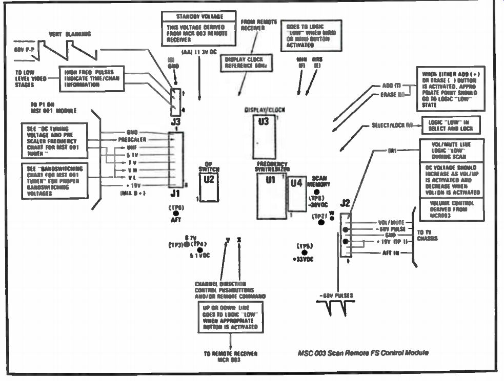
Fig. 8. RCA scan remote control module.
This visual indication can prove to be useful in tracking down various remote control problems.
No or Improper Channel Up/Down Action Scan up and down channel information requires that frequency synthesizer chip (U1) receive proper logic conditions to pins 16 and 17 (from scan channel switch). First, confirm good ground connection at terminals on the MSC-002 module and to up/down switch assembly. If ground connection is open, Scan capability is lost. If either up or down action is lost, check appropriate terminal on MSC-002 module for logic low condition when the correct button is pressed.
No or Improper Add or Erase of Scan Memory
Confirm that proper logic conditions at terminals T and U on the MSC-002 control module are being made. Make sure select-lock switch is in select position and that there is a good ground connection at all terminals on the MSC board. The appropriate add or erase line must go to logic low condition to indicate an add or erase function to the Scan Memory IC (U4). When add or erase functions are not activated, add and erase lines should be idle at logic high (+5 volts DC). No or Improper Channel Change or Skip
These problems are usually associated with the MSC-002 control module. If quick voltage checks do not pin down the problem the best bet is to replace the MSC-002 control module.
The FS scan remote system (see circuit with voltage and waveform notes in Fig. 8) utilizes a frequency synthesizer chip (U1), Op/Amp chip (U2), Memory chip (U4), and an on-screen channel display/clock chip (U3). These IC's and associated components make up the MSC-003 tuner control module for the Scan Remote System. With this system, we will now look at the display/clock interface and other remote servicing procedures. Again, much of the circuitry in the system is similar to that found in the keyboard and scan systems. To locate problems, use the isolation techniques to help you pinpoint the portion of the system that is at fault.
The scan remote system includes the MCR-003 remote receiver which utilizes the remote decoder IC that is not shown. This IC processes channel up/down, set on/off, and volume up/down information from the remote control unit via the preamp unit, and sends appropriate voltages to the MSC-003 control module. The remote receiver also processes function commands from the manual pushbutton assembly located on the TV receiver. Also, located on the remote receiver is a +11 volt DC regulator (Q1101), which provides DC voltages to the remote receiver and preamp board (as long as the TV receiver has AC power connected). A separate power supply transformer (Ti) located on the remote receiver assembly provides AC power (12 volts) to regulator Q1101 for standby and operation voltage to the remote receiver and preamp. Relay K1 provides on-off AC power to the TV receiver.
Remote Module Symptoms
Unable to set time (hours or minutes). Erratic display, loss of time display.
No channel up/down - Remote.
No channel up/down - Manual buttons.
No channel up/down - Remote or Manual.
No or improper volume up/down - Remote.
No or improper up/down - Manual buttons.
No or improper volume up/down - Remote or Manual.
No remote control action.
No on/off action from either remote or manual buttons.
Service Checks
Check all interface connections and wiring to and from the MSC-003 control module, remote receiver MCR-003, Preamp MCY-003, and other assemblies associated with this system.
Unable To Set Time
Display problems can be defined as a loss of, erratic, or distortion on screen digit display with otherwise normal operation. Such problems are usually confined to the clock and display IC located on the MSC-003 control module or to connector problems. If these problems are encountered, replace the MSC-003 module. A defective display assembly may also cause instrument video problems on the sets screen. If video problems are suspected as being caused by the display system, remove connector P3-MSC and see if the problem has been cleared.
Failure of the system to maintain the correct time-of-day is a comparatively improbable situation without any other symptoms being evident.
Make Following Checks If A Problem Is Encountered: Check for possible intermittent power interruptions. If power to the TV set has been interrupted, the time-of-day displayed will be lost when power is restored - requiring the clock to be reset.
Check the time-set switches and cabling for any possible intermittent connections.
If the clock and display is not operating properly, then check for proper DC voltages around the pins of the U3 IC located on the MSC-003 module. If no reason for an incorrect DC voltage can be found then the U3 IC chip may be defective and will have to be replaced. If the chip is hot to the touch it may well be defective.
Remote Scan Turn On/Off Problem Notes In the scan remote system the MCR-003 is used in the CTC-92 and 93 chassis and the MCR-004 is used with the CTC-97 chassis. Repair of the remote receiver is accomplished by the substitution of the remote amplifier module.
Because the CTC-92, 93 and 97 chassis are of the Extended-Life design, a no-turn-on symptom can, of course, be a fault in the TV chassis rather than the remote receiver module. Thus, it is good to use a simple procedure to assist in locating the exact fault area.
The triac is not used in the FS Scan remote systems. Instead, a relay is used as the off/on switch.
The relay driver or switch in each case is a transistor, again controlled by preceding logic circuitry. The relay driver in the MCR-003 is a PNP device with the emitter connected to the 16 volt source through the relay winding. Thus, if the emitter is connected to ground with a clip lead, the TV set should turn on. The relay driver in the MCR-004 is essentially an NPN device so that the collector lead may be shorted to ground to turn-on the set.
You may think the above procedure is not required because an audible click is heard from the relay when the on button is depressed. However, this is not always so. Don't forget that an audible click does not rule out the possibility of oxidized or otherwise defective relay contacts. Of course, this type of problem can be isolated simply by shorting the relay contact terminals 2 and 5 together. If the set does not turn on with this test, the problem is within the TV chassis.
REMOTE RECEIVER POWER SUPPLY (RCA CTC-48-68)
We will now look at some RCA remote control power supply circuits and service tips used in the CTC-48 through CTC-68 chassis series. These sets have the stepper system circuits.
Power Supply Circuit Analysis
As you will note in Fig. 9 there is nothing complex or unusual about this power supply circuit. The primary of the remote power transformer, T105, is protected from an overload by a .2A fuse, F103. A metal oxide varistor, RV101 is across the AC line to protect the triac and other devices from any power line surges and spikes. You may want to add a MOV to any sets you find that do not have one in place, especially if you have had line surge damage to the triac and/or remote receiver devices. Addition of the MOV will help insure against other component failures. Make sure you add the MOV after, and not ahead of, the fuse.
Approximately 12 volts AC from terminal 5 of the secondary of T105 is rectified by CR1105, filtered by C1117, and Zener diode regulated to 16 volts DC by CR1101. The set cannot be turned on either by the manual off/on button or by the remote transmitter if this 16 volt DC supply is missing. If the supply is absent just check with an Ohm meter to confirm the presence of an open or shorted condition in either the rectifier or the Zener diode. If either of the devices is shorted, the .2 A fuse will be open.
An AC voltage check at T105, pin 5, will reveal any possibility of a defective power transformer, although the line surge required to damage the device is usually very high.
One somewhat unusual symptom is that as long as the off/on button is held depressed, the set will remain on with distortion in the sound. As soon as the button is released, the set will turn off. An open C1117, 2504' capacitor, is probably the cause of this symptom.
The top of the remote power transformer secondary, pin 9, delivers AC which is rectified and used to supply -150 volt DC bias to the high impedance remote receiver microphone or transducer. If this supply is not present, or very low, the sensitivity of the remote receiver will be greatly reduced.

Fig. 9. Power supply circuit for remote receiver.
Caution:
When measuring this bias voltage, use a meter with a high input impedance like a FET or VTVM. A volt-ohm meter will load the circuit and give a lower reading than the true voltage value, ff the supply voltage is low or missing, possible causes are a leaky or shorted CR1103 or a defective remote preamp module.
REMOTE CONTROL LOGIC SYSTEMS (RCA CTC-74, 81 CHASSIS)
We will now discuss the stepper system used in several RCA color TV remote control systems. These electronic control systems contain gates which are used to allow remote manipulation of the on/off, channel change, volume level, color level and tint control range. Some combinations of these control functions are used in all RCA remote control systems. This logic circuitry in the later models is modular in design so that most repairs can be completed with a simple module change.
One of the least complex and most widely used logic circuits found in the RCA remote systems is the volume stepper system. Because it is not a plug-in module and must be repaired by the technician we will look at its circuit operation and give some troubleshooting information. Now, follow along with the partial stepper circuit shown in Fig. 10.
Volume Stepper
In the volume stepper, two flip-flops or bi-stable multivibrators controlled by a pulse from the Schmitt trigger ultimately determine the logic state of an OR gate which controls the on/off function of the main TV receiver. The OR gate consists of diodes CR12 and CR13, one or both of which must be on (forward biased) to hold the on/off driver, Q11, in saturation. When this transistor is held in saturation, the enabling device is energized to provide the triac gate pulse.
Another pair of diodes controlled by flip-flops, CR10 and CR11, comprise an AND gate which steps the volume through three levels. In series with each of the diodes is a resistor which is switched in parallel with the volume control when that particular diode is forward biased. The smaller the total resistance, the louder the volume. Therefore, when the set is first turned on, the volume is at maximum because CR10 is forward biased by the on condition of Q10 (collector is at logic low). Resistor R30, which is in series with CR10 is the smaller of the two. With the second push of the stepper switch, CR11 is forward biased by conduction of Q8 placing R31 across the volume control. Since the total volume control resistance is thus increased, the set is now at medium volume. With the third push of the stepper switch, Q8 and Q10 are off. Because neither resistor now parallels the volume control the TV sound level is now lowest (muted). Again, referring to Fig. 10, we see the collector of the keyer transistor, Q4, may be taken low either by base bias provided by an ultrasonic signal from the remote transmitter or by manual activation of the stepper switch. The rather poorly shaped pulse produced, will reverse bias CR5 and turn off Q5, the first transistor in the Schmitt trigger. The second transistor in the Schmitt trigger, Q6, which is normally held off by the saturated state of Q5, turns on and a square wave is thus produced. The primary purpose of the Schmitt trigger is to square up the poorly shaped pulse from the keyer transistor. This square wave, of course, is used to provide gating for the first flip-flop.
The flip-flop is a bi-stable circuit which can exist in either of two stable states indefinitely and has a memory. When power is first applied to the flip-flop, the transistor that conducts first is the one with the larger collector load resistor. It will remain in that state with one transistor on and the other off until it receives a gate pulse. It will then switch states and remain so until the next gate pulse. Gating for the first flip-flop is provided by the Schmitt trigger. The gate pulse for the second flip-flop is provided only when the second transistor in the first flip-flop is on. Therefore, while the first flip-flop changes state with every push of the stepper switch, the second flip-flop changes state only every second push of the switch.
As shown in Fig. 10, CR12 conducts when Q8 is off (collector high) and CR13 conducts when Q10 is off. Therefore, the TV set remains on as long as either or both transistors are off.
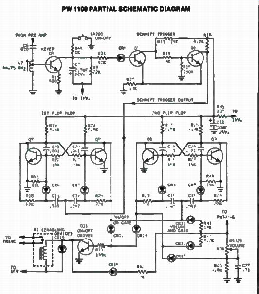
Fig. 10. Partial schematic of an RCA remote unit.
From the preceding information, it appears that the entire system is a complex switching network. Indeed, any logic gate may be schematically represented as a switch. It must be remembered, however, that either logic high or logic low can be chosen as the on state.
Since the collector of any transistor in the system is at logic high when the transistor is off, the logic low condition may be simulated simply by shorting a certain collector to ground. Referring to the schematic in Fig. 10, you can see that when the TV set is off, Q4, Q6, Q7, and Q9 are all off. All things being normal, we need only to momentarily short the collector of one of those transistors to ground to turn on the TV set.
Because of the memory characteristic of the flip-flop, the set will remain on until it receives another command. Using this clip lead method, it is possible to step the system through the four separate states shown on the chart. Also, this method will help you to determine whether a particular circuit - the keyer, the Schmitt trigger, or one of the flip-flops - is defective.
Turn On/Off Problem Notes
The entire remote control receiver circuitry in the Frequency Synthesis Scan System is contained on one of two modules. The MCR-003 used with the CTC92 and 93 chassis and the MCR-004 used with the CTC97 chassis. Repair of the remote receiver is accomplished, of course, by the substitution of the remote amplifier module.
The CTC92, 93 and 97 chassis are designed in such a way that a no-turn-on symptom can, of course, be a fault in the TV chassis rather than with the remote receiver. Thus, we will now look at a simple procedure to assist you in determining where the trouble is to be found.
The triac is not used in the frequency synthesis scan remote systems.
Instead, a relay is used as the off/on switch.
The relay driver or switch in each case is a transistor, again controlled by preceding logic circuitry. The relay driver in the MCR-003 is a PNP device with the emitter connected to the 16 volt source through the relay winding. Therefore, if the emitter is connected to ground with a clip lead, the TV set should turn on. The relay driver in the MCR-004 is essentially a PNP device so that the collector lead may be shorted to ground to activate the set.
If you hear a click of the relay this does not always mean that the relay is good, as the relay contacts could be oxidized and not make contact.
However, this problem can be checked by shorting the relay contact terminals 2 and 5 together. If the set does not turn on with this test, the problem is then isolated to the main TV chassis.
MAGNAVOX "STAR" TV TUNING SYSTEM BASIC SYSTEM OPERATION
This electronic tuning system has four main units: These are the keyboard assembly, the remote receiver assembly, the transmitter unit, and the tuning assembly. The main parts of the electronics are located on four modules: the power supply module, the logic module, the tuner control module, and the video clock module. Some models have a time clock display module. Note the block diagram for the Star System in Fig. 11.
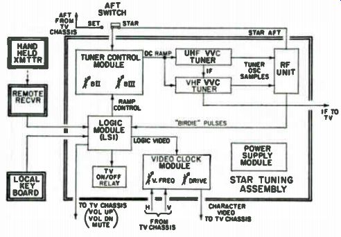
Fig. 11. Block diagram of Magnavox STAR remote system.
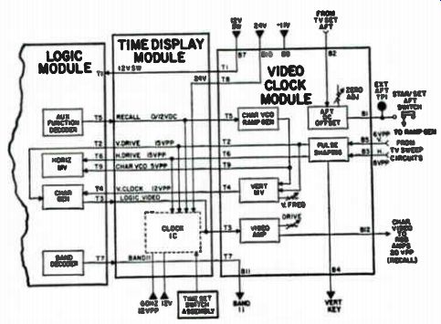
Fig. 12. Video clock and time display modules.
One of fifteen different frequencies are fed from the hand unit transmitter to the remote receiver. The output of the receiver is then coupled to the logic module. A keyboard unit on the set can also be used to control the Star System. In either case, the logic circuits control all functions. The logic circuits are contained within LS! IC's. This custom made device controls TV set off/on, volume level, channel changes and mute. A "logic" video signal, consisting of rectangular pulses, passes through the video clock module to the luminance circuit in the TV chassis.
Horizontal and vertical deflection voltages from the TV set serve as timing pulses.
The tuner control module applies a DC ramp voltage to the voltage variable capacitors, or VVC, tuners. The LSI causes the DC ramp, or tuning voltage, to change when a new channel is selected and shifts the tuner oscillator to a new frequency. The tuner IF output signal is then coupled to the IF module on the TV chassis.
A sample of the tuner oscillator signal is coupled to the RF unit. The RF unit contains an internal crystal controlled oscillator which is used to produce "birdie" signals during the tuning cycle. The "birdie" signals are processed in the LSI and provide precision control over the DC ramp voltage and tuner oscillator frequency.
An AFT circuit in the RF unit provides precise correction of the DC tuning ramp in the tuner control module. The AFT correction circuit in the
TV chassis may also be used if necessary. In most cases, the AFT switch should be operated in the Star position. The set position is used when a wider pull-in range is required to correct the larger carrier frequency errors found on some cable TV systems.
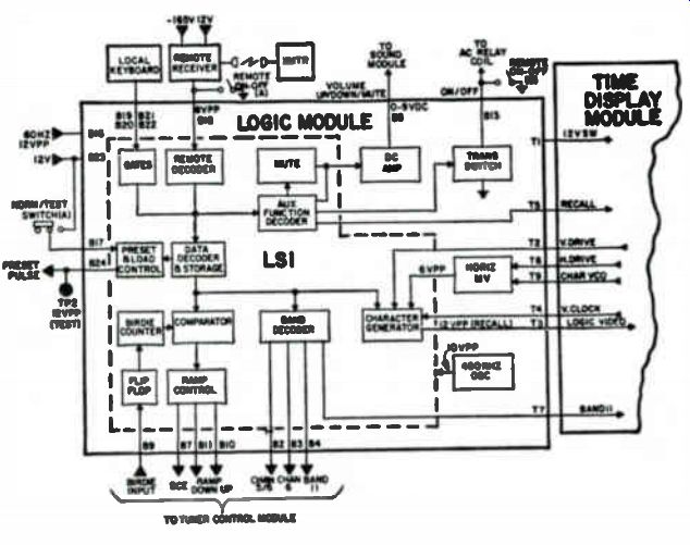
Fig. 13. Logic module found in STAR system.
Video Clock and Time Display System
The circuits on the video clock module are involved with the development of the character video signal. These circuits consist of the character VCO ramp generator, the pulse shaping circuits, and the vertical multivibrator. The remaining circuits are located on the logic module and include the horizontal multivibrator and the character generator. Note block diagram in Fig. 12.
When the recall button is depressed or when a channel is selected, a DC voltage is applied to the character VCO ramp generator. The output goes high (5V) and stays high as long as the button is held down or until the tuning cycle is completed. This voltage determines the frequency of the two voltage-controlled multivibrators and the frequencies determine the size of the characters displayed on the screen. When the recall button is released or the tuning cycle completed, the characters remain at maximum size for a moment or two and then decrease in height and width until they suddenly disappear. This reduction in character size is caused by the character VCO signal ramping down to zero voltage gradually, rather than cutting off abruptly. Timing pulses from the TV deflection circuits are shaped and applied to the multivibrators to key them off at the proper time.
When the vertical multivibrator is first turned on, it oscillates about 1 kHz. As the character VCO signal decreases slowly from maximum to zero voltage, the oscillator frequency increases to about 4 kHz. Maximum vertical size is produced at 1 kHz. As the frequency is swept upward to 4 kHz, the vertical size of the character diminishes until the oscillator is cut off. The frequency of the vertical multivibrator can be varied with the vertical frequency control on the video clock module. This control allows the vertical size of the channel number display to be adjusted.
Logic Module Each key on the local keyboard produces a BCD number on the four output lines. These voltages are coupled through gates to the data decoder and the auxiliary function decoder circuits in the LSI on the logic module which is shown in Fig. 13. When the transmitter is used to operate the system, the signal is amplified by the remote receiver and fed to the remote decoder. The remote decoder portion of the LSI contains a "frequency window" circuit which blocks out extraneous signals outside the 34 kHz to 44 kHz frequency range. Special circuits "decode" the transmitter signal by converting specific frequencies to a corresponding BCD code. The output voltages parallel the BCD lines from the keyboard gates so that either the transmitter or local keyboard may be used to control the system.
The data decoder circuit accepts all BCD information relating to the selection of TV channels, and rejects all BCD data relating to the auxiliary functions. In a similar manner, the auxiliary function decoder accepts BCD information relating to the on/off, volume, mute, and channel recall functions, but it rejects all TV channel selection data.
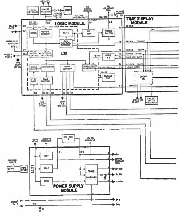
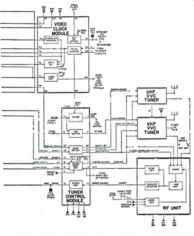
Fig. 14. Remote system signal flow block diagram.
----------------
Table 1. Star Troubleshooting Guide f or In-Home Service.
1. Transmitter has no effect: Keyboard operates normally.
a. Remote Defeat Switch in Off position.
b. Transmitter battery dead.
C. Sub Transmitter assembly.
d. Sub Remote Receiver assembly.
e. Sub Logic module.
2. Local Keyboard inoperative or erratic: Transmitter operates normally.
a. Sub Local Keyboard assembly.
b. Sub Logic module.
3. Neither Transmitter nor Local Keyboard operates normally.
a. Sub Transmitter assembly.
b. Sub Remote Receiver assembly.
c. Check for external signal, such as a Security Alarm.
d. Sub Local Keyboard assembly.
e. Sub Logic module.
f. Replace Power Supply module. Check DC voltages before changing.
4. No control of Volume or Mute other functions normal.
a. Sub Audio module on TV chassis.
b. Sub Logic module.
5. No Channel Recall; other functions normal.
a. Sub Video Clock module.
b. Sub Time Display module.
C. Sub Logic module.
6. Problems with time display; channel characters may not be displayed.
a. Sub Time Display module.
b. Check Time Set switch assembly connection.
c. Check P111 connection on Time Display module.
7. TV set will not turn On with Transmitter or Local Keyboard.
a. Master Power switch not On.
b. Place Remote On-Off switch in Off position.
(1) If set comes On, replace Logic module.
(2) If set does not come On, check line voltage, line cord, Master Power Switch, circuit breaker, module and plug connections, On Off Relay, Power Supply module.
8. Random shut-off of TV set.
a. Momentary loss of AC power.
b. Check the AC input circuit.
c. Modules or plugs are not seated firmly.
d. Check for intermittent contacts on the Top Interconnect board and the Bottom Interconnect board. Clean male pins with Magnavox Contact Cleaner/Lubricant spray, Part No. 171378-1.
e. Sub Logic module.
f. Change Power Supply module after checking DC voltages.
9 Stations are mistuned; other functions normal.
a. Place AFT switch in the "STAR" position.
b. Cable TV signal off frequency. Place AFT switch in "Set" position.
c. Check Band adjustments.
d. Sub Tuner Control module.
e. Sub Logic module.
10. Snowy picture.
a. Check setting of Sharpness control.
b. Check antenna system.
c. Check setting of RF Delay control on TV chassis.
d. Check AGC voltages on TV chassis.
e. Check RF AGC voltage on tuner.
f. Sub Tuner Control module.
--------------
Servicing the Star Remote System
The signal-flow block diagram in Fig. 14 will serve as a good troubleshooting aid in problem diagnosis. This diagram locates the major circuits and functions within the system. Signal flow between circuit functions and modules is depicted along with significant AC and DC voltages. The diagram can be used to determine which module might cause a particular trouble symptom and help pin-point the problem.
Many of the problems that occur in these remote systems can be repaired on a service call by module replacement As an example, the remote hand unit can be subbed with a good unit. The remote receiver unit and local keyboard assembly can also be checked by substitution. When problems occur in the tuning assembly, the modules can be substituted one at a time until the defective one is located. The power supply can also be replaced on a home call. Voltage checks should be made before the power supply is changed. Use the troubleshooting guide in Table 1 for suggested causes of various trouble symptoms.
On the Bench Service
When in-home checks will not locate the fault, then more troubleshooting checks are needed on the shop bench. The main components that become suspect are the VVC tuners, the RF unit, and the interconnections within the tuning unit and between the tuning assembly and 'IV chassis. Some faults may be in the main TV chassis and not in the Star system. For example, a symptom of no picture, no sound or snowy picture may be caused by a defective IF stage or AGC circuit on the TV chassis as well as a VVC tuner problem.