In this Section we will be looking at some electronic video game "chips" and other circuitry. Some logic troubleshooting tips will be given that can be used for video game servicing.
NATIONAL SEMICONDUCTOR VIDEO GAME CHIP
This video game uses the MM57100N IC along with a clock driver chip and power supply. Other brands of video games use this same chip in their units.
This IC provides all of the logic to generate the playing games. The IC generates all timing-sync, blanking, and burst thus, allowing the TV games to be connected to the VHF terminals of the TV set. Note the block diagram of the total game system in Fig. 1.
The game paddles are controlled by two external RC networks.
Resistance and capacitance of each network provide for full-screen movement by developing a time delay of about 16.5 ms. The size of a player paddle is modified by moving the paddle to either the top or bottom boundary and depressing the game reset button. Single-player practice can also be created with this system.
The player paddles are divided into nine different areas that define eight angles that the ball will deflect upon impact. There are two areas in the center of the player paddle which make the ball have zero vertical displacement. The player paddles are transparent in one direction so that in hockey the ball can rebound off the back wall and pass through the defensive player paddle. The machine paddles are also transparent in one direction.
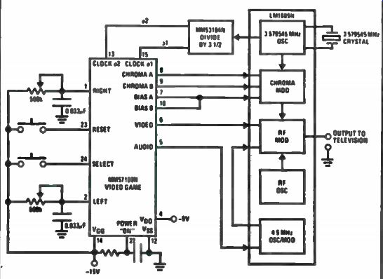
Fig. 1. Video game block diagram.
The ball is always served by the player who won the last point. The serve comes about 1.6 seconds from the time of the last score. After four player hits, the ball speeds up to twice the initial velocity. Each time the ball strikes an object, a signal is generated at the audio output for the duration of the TV frame plus one full additional frame. When the ball strikes the boundaries or a machine paddle, it bounces off the object under the rule that the angle of incidence is equal to the angle of reflection.
Regardless of the angle that the ball is traveling as it hits the front of the player paddles, it will deflect as to which segment it hits.
The score is automatically blanked when the ball is in play. It remains blanked until a miss is recorded; it is then properly displayed on the screen. The game is completed when one player obtains 15 points. At this time, the score remains on and the serve is inhibited until the game reset button is depressed. Both the game reset and select inputs are debounced for 16.5 ms.
The video output signal contains horizontal and vertical blanking, horizontal and vertical sync, and the signal information necessary to generate the picture at the RF input antenna of a TV set. Note circuit diagram of the complete game in Fig. 2. The picture raster is not interlaced. Chroma outputs provide the color burst information and are timed with the video signal.
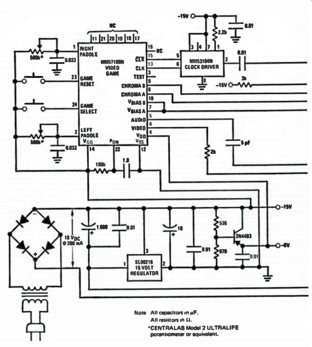
Fig. 2. TV video game circuit diagram.
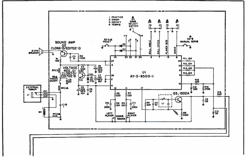
Fig. 3. Circuit for model BG7514 video game. MAGNAVOX VIDEO GAMES (ODYSSEY
MODEL BH7514)
The video game can be powered by either a battery or AC to DC voltage adaptor. It has tennis, hockey, smash, and practice, with skill levels from amateur to professional using ball speed, ball angle, and player size for the more demanding enthusiast. Serving can be either manual, by depressing the serve button or automatic. Automatic features include on screen scoring, which awards a point to the appropriate player or team each time the ball leaves the playing area. Automatic serve will return the ball into play from the side that was awarded the point. This sequence will be repeated until a score of 15 is reached by one side, after which the ball will continue to bounce around with no further hits or scores.
Typical Operation
Set the game selector to a position so that the double arrow is indicating your choice of games by name and picture. Turn TV and Game on. Push the reset button so that the score and ball will be in the starting position. Select the desired ball serve, ball speed, and player size modes via the front panel switches. The Game is now ready to be played. Control by the players is accomplished by rotating the player controls.
Service Adjustments
Do not make any service adjustments until you are sure the fault is within the video game. Check its operation by hooking it to a good operating TV set. When you are sure the trouble is with the game then the following checks and adjustments should be performed. Use nonmetallic tuning tools for all of these adjustments.
2 MHz Oscillator Adjustment
• Connect a frequency counter in series with a 10K resistor and a 0.01 uF capacitor to pin 17 of the U1 chip.
• Adjust the core of coil L1 for 2.01 MHz ±20 kHz.
RF Oscillator Adjustment
• Connect the game to a TV set and defeat the sets AFT.
• Switch TV set to channel 3, center the fine tuning control, and set the video game channel selector switch to channel three.
• While observing the game display, adjust trimmer capacitor CT1 for the best response of the picture.
Troubleshooting
Begin the troubleshooting by isolating the defect to as small an area as possible. Try to narrow it down to the only components that could cause the trouble. A systematic approach will help narrow down the process.
Check over the circuit carefully.
Looking at the circuit in Fig. 3, you will see that the video game is composed of game chip U1, voltage regulator Q1, sound amplifier Q2, 2MHz oscillator Q3, and the RF modulator sub-assembly. The RF modulator unit contains two active components: RF oscillator Q4 and mixer diode D4.
It will depend on the exact symptom as to how you may want to start isolating the problem area. A symptom of no display could be caused by a fault in the game board or RF modulator. The first step is to check the power supply voltage. A good point to check would be at the power on/off switch, S8. If this is within limits move to the emitter of voltage regulator Ql. The proper voltage for the emitter, collector, and base of Q1 is shown in Fig. 3. Use a VTVM or FET meter for these measurements. If the trouble does not appear to be in the power supply move on to a specific stage.
Next place to look is the RF modulator, because if it is not working there will be no video carrier information. Another modulator can be used for a check.
Another way to determine if the RF modulator is at fault or if the game board is defective is to couple the output of the game board to the input of the video amplifier of a working TV set via a coupling or blocking capacitor. Note that it may be a negative picture, depending on which stage the signal was injected into.
Once you have isolated the trouble down to the game board or the RF modulator, it is a simple matter of checking voltages and etc. to determine the defective component. Voltages for the game chip U1 are shown in Fig. 4. Referring to Fig. 4 when the chip is suspected will help confirm any doubts about the condition of the chip. Take note though: read the notes next to each entry before condemning the chip as defective.
The complete schematic diagram for the Magnavox Odyssey model BG7520 video game is shown in Fig. 5. This information, and circuit diagrams can be used for servicing many other models of the Magnavox Odyssey series of video games.
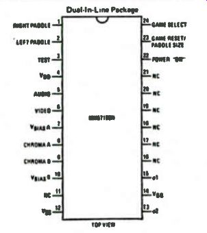
Fig. 4. Pin out for model MM57100N IC chip.
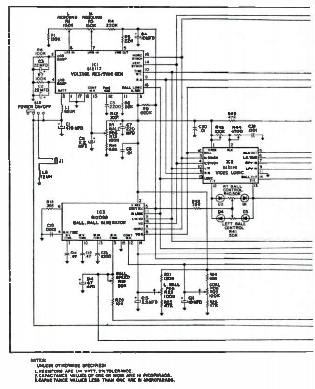
Fig. 5. Magnavox BG7520 video game circuits.
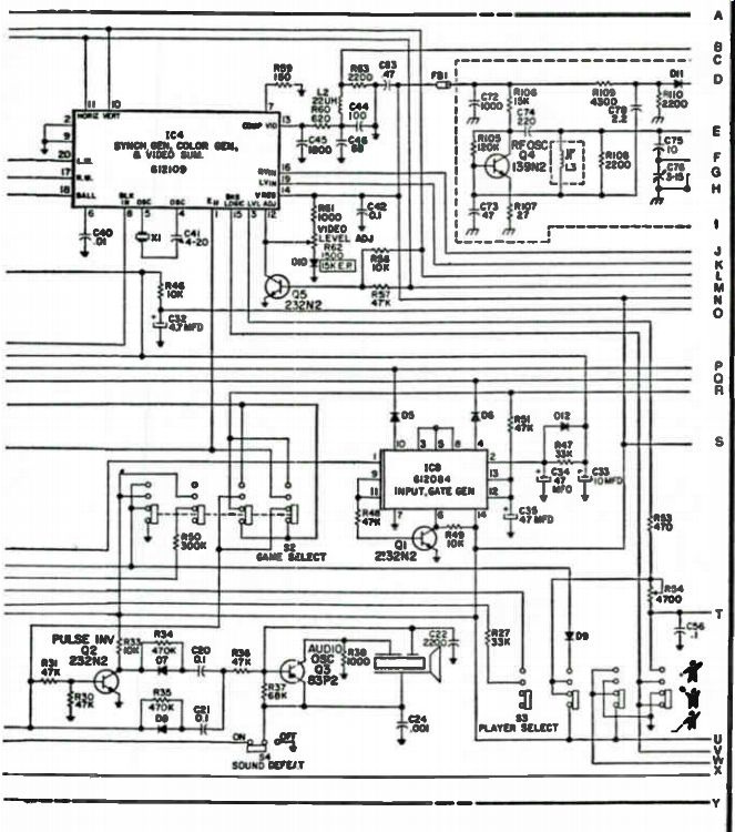
Fig. 5 Magnavox BG7520 video game circuits (continued).
RADIO SHACK VIDEO GAME (MODEL 60-3057)
This video game is similar to many other units made by Radio Shack.
It operates on TV channels 3 and 4 with an RF output level in the 1000 to 1500 micro-volt range. The color and color subcarrier frequency is 3.5795 MHz, and the horizontal sync frequency is 15.734 kHz. The game operates on batteries or with an AC adaptor.
Basic Operation
A block diagram of the 60-3057 is shown in Fig. 6. Off chip circuits involve the power supply, player controls, control board, and RF modulator with antenna switch box.
Pins 3, 4, 5 and 6 of the game chip are the game select pins. Refer to pin outs in Fig. 7. By connecting one of these pins to pin 11 a specific game is selected.
Pins 16 through 19 are the player position controls. Pins 20 through 25 are video/sync outputs. Note that the outputs on pins 21 through 24 are fed through the phase-shifting network for color control. Once passed through the phase-shifting and gating circuits, these outputs are mixed with the composite video and sync, then fed to the RF modulator.
Pin 27 and pin 28 are clock input and output. Note in Fig. 6, a portion of the clock frequency is fed to the phase-shifting network.
Referring to the video game circuit in Fig. 8, transistor Q1 is the audio output device. Audio signals exit from pin 13 of game chip IC1 and are amplified by Q1. Audio output transformer Ti, located in the collector circuit of Q1, couples the audio to the speaker, SP. Transistor Q2 is the voltage regulator. It is a series-pass regulator with the zener diode Z3 in its emitter circuit. Zener Z3 governs the output level of the regulator circuit. The output of Q2 supplies Vdd and Vdd2.
Other voltage supplies are regulated by zeners Z1 and Z2. Both of these zeners are rated at 6 volts, 0.5 watt.
Transistor Q3 is the RF oscillator. This stage is part of the RF modulator, which is a shielded unit. A 60 MHz signal is generated by Q2, which is fed to diode D7. At this point the video information from the game chip is injected onto the 60 MHz carrier. The modulated RF is coupled through transformer L6, a filter, and coax to the switch box. Then the RF is coupled to the antenna terminals of the TV set.
Transistor Q4 on the game board is the trigger switch for the rifle game. This transistor is controlled by the rifle-trigger, located in the rifle circuit. Referring to Fig. 8, the rifle circuit, pin 3 of the DIN plug connects to the trigger switch. By closing the trigger switch, the microprocessor is informed that a shot has been fired. If the shot is on target, a hit is recorded at pin 1 of the DIN plug and fed to pin 12 of the microprocessor chip. To score a hit, light from the target on the TV screen must strike the light sensitive device on the rifle. When this occurs, a pulse is set-up and fed through transistors QI and Q2 in the rifle, which is coupled to pin 12 of the microprocessor IC.
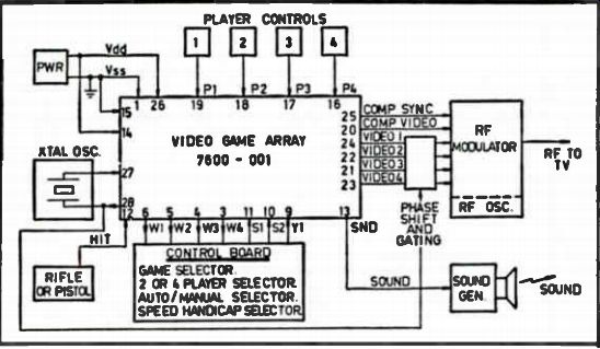
Fig. 6. Block diagram for 60-3057 video game.
Service Adjustments
Do not perform any adjustments to the video game until you are sure that they are required. Take time to carefully fine tune the TV receiver on channel 3 or 4. Use nonmetallic tuning tools for all adjustments. Test equipment required to perform checks and alignment are as follows.
4-digit, 5 MHz frequency counter with 50 mV sensitivity.
RF millivoltmeter (80 MHz).
VTVM or FET meter.
9 volt DC regulated power supply.
Color TV receiver.
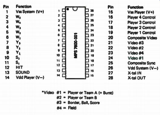
Fig. 7. Pin out for MPS-7600-001 game chip.
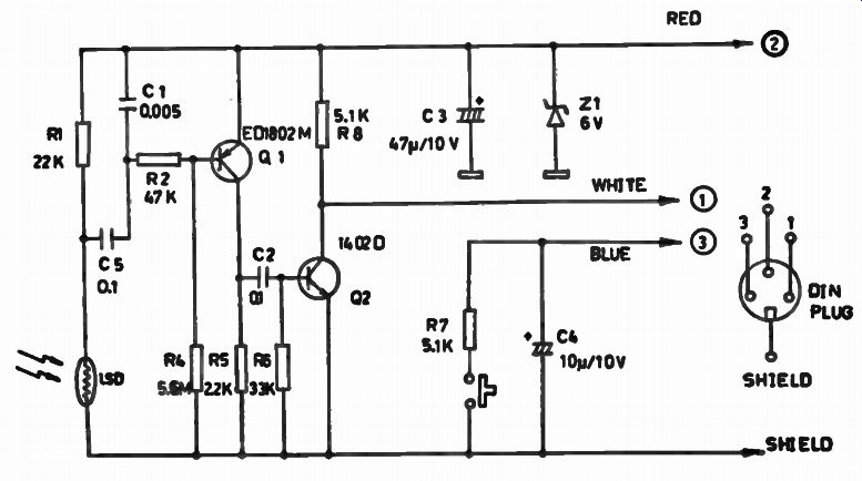
Fig. 8. Complete schematic for Radio Shack 60-3057 video game.
GAME CHIP REPLACEMENT
If the game chip is defective, carefully remove with solder sucker, etc. When replacing the chip, be sure to position the pins properly with the dot next to pin 1. Do not handle the IC by its pins. Avoid static build-up.
Clock and Subcarrier Frequency Check
Connect the video game to the 9 volt DC regulated power supply.
Connect the frequency counter to pin 28 of game chip IC1 through a 100 K isolation resistor as shown in Fig. 9. Adjust trimmer capacitor CT1 to give a frequency of 3.57954 MHz ±200 Hz. This frequency adjustment is critical for proper horizontal sync and color burst.
Symptom/Cause Data
We will now look at several common game symptoms along with their probable causes. If the exact symptom is not shown select one that comes close to your trouble; it may point you in the right direction and you will be able to localize the defect rapidly.
No Sound. Check speaker and wires. Check transistor Q1 and associated circuitry.
No Clock and Color Subcarrier. Defective game chip. No power supply voltage. Shorted Zener diode Z3 or transistor Q2.
No Voltage Regulation. Defective zener diode Z3 or transistor Q2.
Leaky capacitor C7, C8, or C12.
Erratic Ball, Game, or Counting. Low battery voltage. Check voltage regulator.
Certain Games Do Not Work. Defective game selector S2. Cold solder joint. Defective game chip IC1.
No Color Display. Defective voltage regulator Z1. Defective chip IC2 or IC3.
No Hits With Target Game. Defective transistor Q4. Broken wires to the rifle or other game controls. Defective rifle DIN socket.
Parts Replacement Tips
Whenever possible, replace defective parts with factory components.
Common components, such as resistors, diodes, common transistors and capacitors can usually be used from your local electronics supply house.
However, special items such as microprocessors, logic gates, transformers, and coils should be ordered from the manufacturer.
TROUBLESHOOTING VIDEO GAME CIRCUITS
We will now cover some tips for troubleshooting some of the logic circuits found in various video games. Some logic probe information will be given along with logic gate operation. Also, the way analog and digital logic circuits differ in operation, and thus troubleshooting techniques, will call for new and different techniques.
Using the Logic Probe
The logic probe gives you a quick indication if the circuit is working at all. As an example, a control should go to a logic high to turn on another device under certain conditions. A logic probe will quickly indicate if the line ever goes high, or may be stuck at a high level.
Some probes with a memory function can be used to monitor a line for intermittent pulses, or noise spikes (glitches) that will upset logic functions. Thus, the probe performs as a "1" or "0" read-out instrument that is operated from the power supply of the circuit under test to provide simple, direct and low-cost test data.
Logic probes are powerful troubleshooting tools because of their portability, price and simple operation. The logic probe is a "high or low" state device that provides an indication of a high level, low level, or a faulty level signal. Detectors within the probe determine if the signal being checked is above the high level, below the low level, or in between these two.
Most logic probes provide the following features.
-Hi or Lo pulse indication
-Pulse train indication
-Stretching display for short pulses
-10 nano-second pulse response
-Pulse memory
-Undefined logic state indication
-Will test multi-logic family devices

Fig. 9. Clock and subcarrier frequency adjustment set-up using a frequency
counter.
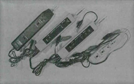
Fig. 10. Some logic probes that are now on the market.
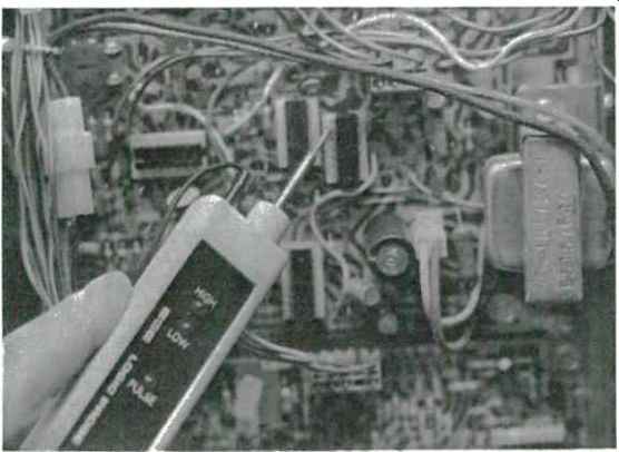
Fig. 11. Continental Specialties LP-2 Logic Probe.
Figure 10 shows a line-up for some of the various logic probes that are now available. From left to right they are the Continental Specialties Corp., model LP-1 and LP-2 logic probes, the DP-1 digital pulser and the B&K model DP-50 logic probe.
Probes indicate logic conditions by using lamps or LEDs. Usually a lit lamp indicates a logic "1" or logic high. Some will use colored LEDs in various patterns to show logic states. These LEDs are used to show if a circuit is high, low, pulsing or has an open circuit.
The Continental Specialties LP-2 logic probe shown in Fig. 11 is protected against over-voltage and reverse voltage on its power leads. To use this probe connect the black clip lead to the common ( - ) and the red clip lead to the ( + ) Vcc of the system under test. In order to minimize the possibility of power supply spikes or other spurious signals from affecting the operation of the probe, connect the power leads as close to the node to be tested as possible. Refer to Fig. 12 to interpret the LED readout for the LP-2.
The B&K DP-50 digital probe (shown in Fig. 13) is designed for quick analysis of digital circuits, and is compatible with TTL, DTL, RLT, CMOS and high-noise immunity logic. Three LEDs at the probe tip visually display pulse presence and high "1" and low "0" logic states. An incorrect logic level or an open pin is indicated by no illumination of the pulse LED. Two switches allow you to select TTL or CMOS logic thresholds, and pulse stretch or memory modes. In the pulse stretch mode, short duration pulses are stretched for a clear visual indication. In the memory mode, a single digital pulse causes a LED to remain lit until it is reset. The probe thus has the ability to "freeze" the display of the digital/logic action.
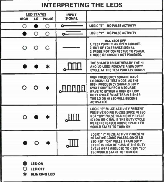
Fig. 12. Chart for LP-2 Logic Probe LED interpretations.

Fig. 13. B & K DP-50 Logic Probe.
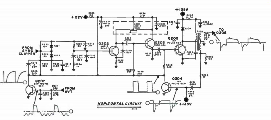
Fig. 14. Analog circuit.
Pulse Stretcher
Probably the most important feature of a logic probe is its ability to stretch a 10 nano-second pulse to 100 ms so that the LED will register and you can "see" it. This stretch is accomplished by using the leading edge of a short pulse to trigger a flip-flop whose time delay is 100 ms. Single pulses flash the probes LED lamps once while pulse trains will usually always blink on at a 10 Hz rate, regardless of frequency. The big benefit here is just in knowing that pulse activity is present, which generally is all the information that is required.
Digital vs Analog Troubleshooting
When troubleshooting circuits with analog devices, you need only test resistance, capacitance, or turn-on voltages of components with two or three states. The total circuit may be quite complex, but each component in the circuit performs a simple task and its operation can usually be easily checked. As you will observe in Fig. 14, each resistor, capacitor, diode and transistor can be tested by using a signal generator, VTVM, diode checker, or scope by using the conventional troubleshooting techniques. But with integrated circuits, these various components cannot be tested and it is now necessary to troubleshoot the total circuits in the system.
The difference between discrete circuitry and today's digital ICs is in the complexity of functions performed by these sophisticated devices.
Unlike discrete devices, modern digital ICs perform complete, complex functions. Instead of observing simple characteristics, it is now necessary to observe complex digital signals and decide if these signals are correct.
Verifying proper component operation now requires observing many inputs while simultaneously observing two or more outputs. Thus, another difference between analog circuitry built from discrete components and digital ICs is the number of inputs and outputs for each component and the need to check each one simultaneously.
In addition to simulating test signals and complexity of functions at the component level these ICs have caused a new degree of complexity at the circuit level. If you have enough time, these circuits can be studied and their operations understood, but the average technician just cannot spend that much time. Without going into all of the circuit's intricate operations, it becomes necessary to have a technique for quickly testing each component rather than trying to isolate a failure to a particular circuit and testing for expected signals.
In order to solve these problems and to make troubleshooting of digital circuits more efficient, it is necessary to take advantage of the digital nature of the signals involved. Tests and techniques designed to troubleshoot analog circuits do not take advantage of the digital signal and are thus less effective when used to troubleshoot digital circuits.