In this Section we will cover circuit operation and service tips on the electronic systems used in cassette and 8-track tape recorders. This will also cover stereo pre-amps, oscillators, auto-tape-stop circuits and bias erase circuits.
INTRODUCTION TO TAPE RECORDING
Recording a tape starts with an audio information signal or the intelligence to be recorded. To do this, a signal current is passed through a coil in a recording head. Tape, with a magnetic coating, is fed past the poles of the coils in the record head. The signal is recorded on the tape as magnetic fluctuations. The degree of these fluctuations is in proportion to the magnitude of the variations in the magnetic field.
For playback, the tape is drawn past another, or the same head in the machine. Magnetic variations on the tape induce current fluctuations in the head. These currents are amplified in the recorder circuits and reproduced as originally recorded on the tape. Because the frequency response of the playback amplifiers are not linear, some compensation circuits must be used for equalization.
A typical recording circuit is shown in Fig. 1. Audio from a microphone is fed to the gate of the n-channel MOSFET, Q1, pre amplifier. Because the output from the microphone is linear (flat response), the gain of Q1 must also be uniform over the frequency range.
The output from the MOSFET is developed across control R1.
A higher level signal (from turntable, tuner, or other tape unit) is fed to the line input across potentiometer R2. These input line signals are mixed via isolating resistors R3 and R4 and fed to bipolar transistor Q2.
Transistors Q2 and Q3 serve the dual function of amplifying the signal while providing the circuitry to produce the proper frequency equalization.
Equalization or curve matching is accomplished through the use of feedback. Linear feedback takes place across resistor R5, but capacitor C4 causes the feedback to decrease as the frequency increases. Because gain is not reduced by feedback at the high frequencies, the needed treble is provided.
Resistor R6 and capacitor C5 feed signal back from the output of Q3 to the emitter of Q2. Because the impedance of C5 decreases as frequency increases, the high frequencies are fed back more readily than the lows.
Thus, the low frequencies are emphasized here. This base boost is required to compensate some for the characteristics of the record head and the tape. The output from Q3 is fed to the record head.
Transistors Q4 and Q5 are part of the high-frequency multivibrator oscillator circuit. Capacitor C8, across the transformer primary of this circuit, sets the resonant frequency of the tank circuit and the frequency of oscillation. Capacitor C3 reduces the distortion of the sinusoidal output of the oscillator. Both the signal from Q3 and the high supersonic frequency are fed to the record head. The high frequency signal biases the record head to a specific level so that the signal rides on the oscillation. Because the bias level affects the frequency response, a bias level adjustment is put into this circuit to set the flow of high-frequency current through the head.
The meter in the output circuit measures the record signal level. Control R9 calibrates the meter. Resistor R8 and capacitor C6 filter the high frequency so that it will not be fed back to the tape amplifier. It also helps in keeping the bias current out of the meter circuit. Capacitor C7 enhances the filtering action in the meter circuit.
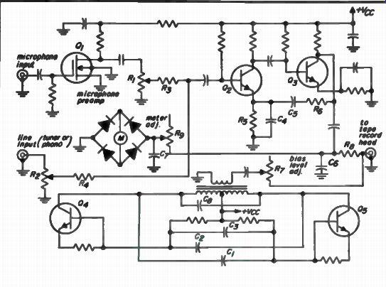
Fig. 1. Tape recorder pre-amplifier circuit.
THE PLAYBACK SYSTEM
In the playback mode the tape preamplifier must have the correct frequency characteristics. Refer to the playback circuit shown in Fig. 1.
Transistor Q1 provides the high impedance that should be "seen" by the playback head and also supplies a constant gain over the entire audio bandwidth. The output level is varied by control R1. The output from R1 is fed to amplifier Q2 and Q3. The output signal from Q3 may be used to drive one of the power amplifiers in the tape system.
Parallel circuit R2-C1, in Fig. 2, furnishes some treble boost to compensate for the high-frequency roll-off of the playback head. R3-C2 provides the bass boost to simulate the playback curve. The action of both feedback circuits, discussed with respect to the record amplifier in the Fig. 1 circuit, also applies here.
The inductance of the playback head must also be considered when measuring the playback characteristics. Playback curve requirements must be satisfied for the entire circuit. In the set-up for measuring the frequency characteristics, the playback head must be placed between the audio test generator and the input to the playback preamplifier in series with the signal. The frequency response of the tape-head preamplifier combination must produce a curve that will give a linear output across the audio spectrum.
STEREO TAPE SYSTEM
Each channel of a stereo system has one record preamplifier and one playback preamplifier. Many good, high quality decks use two heads, an erase head and a single play/record head. The better machines use three heads, an erase head, a record head, and a playback head. Play/record heads, used on two-head machines, must be a compromise to perform both record and playback functions satisfactorily. The three-head decks are sufficiently versatile so that each head offers optimum performance for its particular function.
Each head intended for stereo operation has two individual coils. Two tracks (one for the left and the other for the right channel) are recorded when the tape travels in one direction from the supply reel to the take-up reel, and two other tracks are recorded when the tape travels in the other direction. On 8-track and some cassette recorders more tracks are recorded.
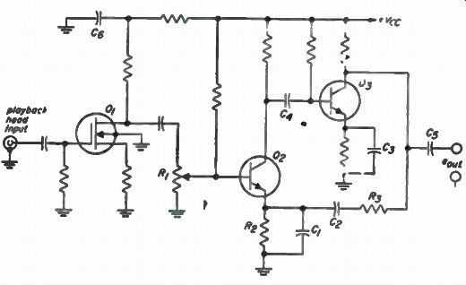
Fig. 2. Tape playback pre-amplifier circuit.
As shown in Fig. 3, tracks 1 and 3 are recorded when the tape travels in one direction, and tracks 2 and 4 are recorded when the tape is turned over and the functions of the two reels are interchanged. Two coils are necessary to record four tracks on the tape. The two channels recorded on two of the four tracks require two individual playback amplifiers.
Many of the newer stereo tape recorders are now very versatile. You can use them to make sound-with-sound recordings on machines using two heads. As an example, it allows you to vocalize (sing along with Mitch if you please) on one track while listening to music that was previously recorded on the other track. And of course you can also add (sound-over sound) on both tracks. The circuitry for sound-with-sound operation operates as follows. One track on the head is switched so that it will play through its amplifier while the second track on the head is connected to the record amplifier. You can listen to music from the track feeding the playback amplifier while recording on the track connected to the record amplifier and to its respective coil on the head.
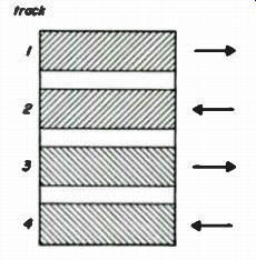
Fig. 3. Directions tape tracks are recorded.
Additional versatility is possible if the stereo recorder has three heads. Music recorded on one track, possibly the left channel, is fed from the playback amplifier to the line input on the right-channel record amplifier. A live signal is simultaneously routed to the microphone input on the right channel preamplifier. Both signals at the right channels are then mixed. The composite signal is then recorded on one-right channel track. This recording method is known as sound-on-sound, and is achieved by connecting the output from the left-channel playback preamplifier to the line input on the right-channel record preamplifier. The left channel is shorted out at the record head. The right channel record and playback amplifiers are connected in the normal way to the right-channel coils of the respective record and playback tape recorder heads.
GENERAL CASSETTE TAPE RECORDER DAT
A Stereo cassette tape players/recorders are used to play back pre-recorded tapes and also to record from microphones or other sources such as AM or FM tuners, phono or Aux. Many cassette tape units feature playback and record, fast forward, play, stop-eject, pause and automatic tape shut-off. Some deluxe units will have tape select, VU meters, record level controls, digital counter and record indicator light.
Cassette Tape Specifications
The standard cassette tape width is 0.150 inches (slightly more than Ye inch) and is used for both monaural and stereo recordings. Figure 7-4 illustrates the track arrangements for these cassette tapes. As shown, a mono recording consists of two tracks; each track is 0.59 inch wide with a guard band of 0.032 inch between the tracks. Stereo recordings consist of two pairs of tracks. Each stereo track is 0.024 inch wide, separated by a guard band of 0.011 inch. In addition, a guard band 0.032 inch wide separates each pair of tracks, thereby ensuring playback compatibility of the stereo recorded tape.
The total track width of each stereo pair, plus their guard band, is equal to one mono track width. Stereo pre-recorded tapes will be reproduced in mono, on a mono tape unit. The left and right track signals will be combined by the playback head and be reproduced as a mono program. Recordings which are made on a mono unit will be reproduced only as mono, even on a stereo recorder system.
Cassette Electronics Circuitry
This cassette tape player/recorder uses an independent tape amplifier circuit board, with inputs and outputs connected to the systems other circuits. Other electrical connections to the main systems PC board are made directly or through switching networks.
The drive motor for this player/recorder is powered by 12 volts supplied from the main circuit board.
Refer to Fig. 5 for the electronic circuits used with this cassette tape player/recorder.
PLAY/RECORD AMPLIFIER OPERATION
This tape player/recorder uses four transistors and two integrated circuits (IC's). Each channel uses an IC for record/play amplification and equalization and one transistor for additional equalization. Also, one transistor functions as the bias oscillator while another transistor is used for B+ filtering.
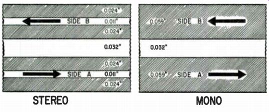
Fig. 4. Cassette track patterns.
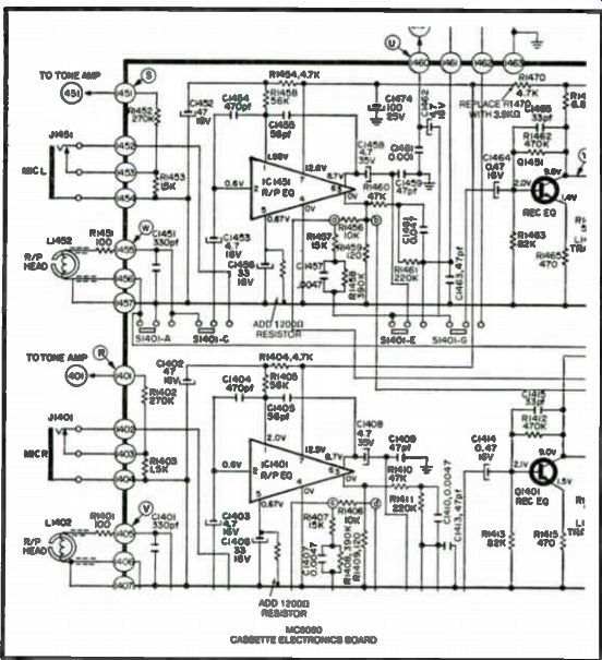
Fig. 5. Cassette electronic circuits (stereo).
A frequency compensating network provides the equalization required for proper record/playback response of the tape.
The S1417 switch (tape select) controls two different networks, one is used with chromium dioxide (CrO2) tapes, and the other one is used with normal (NOR) ferric oxide tapes.
The amplifier circuit board utilizes a transistor in the bias oscillator circuit. Two controls are used to adjust the bias levels. Potentiometer R1701 controls the right channel bias level while potentiometer R1751 controls the left channel bias level. In addition, the unit uses record level controls (R1421) and (R1471) for both right and left channels.
BIAS OSCILLATOR CIRCUIT
The bias oscillator circuitry uses a transistor (Q1701) and a bias oscillator transformer (T1701). This circuit supplies erase current to the erase head L1701 and also supplies bias current to the play/record head.
Bias current goes via recording bias level adjustments R1701 and R1751.
This bias current is combined with the audio output signal after which it is applied to the respective left and right windings of the play/record head.
If the bias oscillator is not operating the tape cannot be recorded properly nor played back. Use the scope to check for bias oscillator operation. The bias oscillator produces a sinewave signal. A defective play/record head may also cause the bias signal to be very low in amplitude. One quick way to check for presence of the bias oscillator signal, without going into the tape unit is to connect another play head to the oscilloscope vertical input channel, and place the test head close to the play/record head in the tape player, and see if the sinewave bias oscillator signal is present on the scope.
Most of the bias oscillator units are sealed and cannot be repaired. If the unit is found to be defective just replace the complete bias oscillator unit.
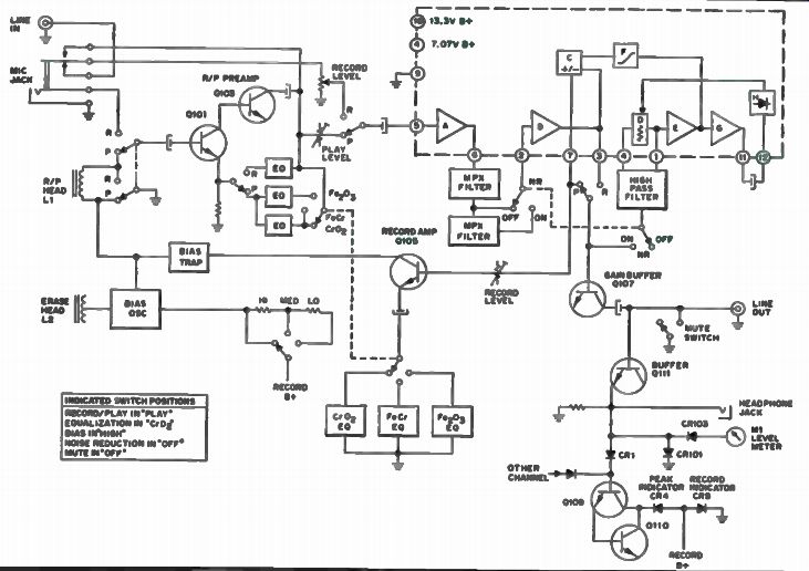
Fig. 6. Block diagram of a cassette tape recorder.
PROFESSIONAL CASSETTE PLAY/RECORD TAPE UNIT ZENITH MC9070
A block diagram for this model MC9070 tape system is shown in Fig. 6. The signal source inputs are shown at the upper left of the diagram.
The inputs are as follows.
Line input.
Microphone jack.
Dual-function record/play head (L1). On the right side of the block diagram are shown these inputs: Line output.
Headphone jack.
A level meter (M1) plus peak and recorder indicators are shown at the upper right corner, while the erase head (L2) is at the lower left.
Cassette Play Mode
When in the play position (with Dolby noise reduction turned off), the signal moves from the record/play head via one section of the record/play switch, to direct-coupled amplifier Q101 and Q103. Another section of the record/play switch selects the desired feedback circuit to provide proper equalization during record or playback. Output of this stage is routed via a preset level control, another record/play switch section, and then to pin 5 of IC101. Refer to the complete circuit diagram in Fig. 7.
IC101 provides both record and playback amplification as well as the circuitry for Dolby noise reduction functions. Between pins 5 and 6, is preamp "A". Externally between pins 6 and 2 are two low pass filters (one is switch selected) to filter out multiplex signal components, or any signals above 15 kHz. This is done to prevent possible interference from these sources. At pin 2 is preamp "B", which connects to pin 3 and mixer circuit "C" functioning as either an adder or subtractor, depending on the operating mode. The output of the mixer "C" connects to pin 7. Then the signal is coupled to another section of the record/play switch, gain buffer Q107 and to the line output jack. A mute switch on this line will short the signal to ground to avoid unwanted signals. This switch will remove the mute action only when the play button is activated.
Switching Dolby noise reduction to on while in the play position, will result in added operating circuits which control the dynamic processing characteristics. The signal will also be routed from pin 7 to the second section of the noise reduction switch and then to a high pass filter connected externally between pins 4 and 1. Internally, between these pins is a variable resistance "D" which has a high resistance at low signal levels. Output of this filter goes to amplifier "D" and then to mixer "C", where it is combined with the original signal processed to pin 7, and then to Q107. In addition, the signal from amplifier "E" is fed to amplifier "G" and is then rectified by a non-linear integrator "H" to provide a DC control voltage. This DC control voltage will vary resistance "D" in such a way that when the control voltage exceeds a certain level, resistance "D" will start to fall, causing an increase in the turnover frequency of the high pass filter. This filter will then attenuate low and mid range frequencies in the signal path processed via amplifier "E". Non-linear integrator "H" functions in a manner that will provide fast gain change action without creating unwanted signals. If transients of excessive levels should occur they will be clipped by clipper "F" resulting in a smooth response action.
The Record Mode of Operation
During the record mode, microphone signals will be processed via the preamp consisting of Q101 and Q103 and is similar to that explained in the play mode of operation. External signals will be routed from the line input. Signals will then be processed via switching contacts on the microphone jack, the R/P switch, IC101 pin 5, amplifier "A", pin 6, low pass multiplex filters, pin 2 amplifier "B" to pin 3, as during play. The signal will also be applied to mixer "C". When noise reduction is on, while in the record mode, the signal will be taken from pin 3, through the record/play switch, then routed via the noise reduction switch and applied to the high pass filter at pins 4 and 1.
This high pass filter will function in a manner similar to that explained for play, but now as part of a positive feedback loop (using mixer "C" as an adder) instead of the negative feedback loop used in play. This will result in record circuit characteristics which are complementary to that of playback.
The output at pin 7 will be connected to record amplifier Q105. From there the record signal will go through a bias trap which prevents the bias oscillator signal from getting back into the record amplifier or other circuits where the bias frequency could cause undesired effects. The bias oscillator serves two functions. One function is to provide a bias to the erase head, while the other is to establish an AC (RF carrier) type bias at the record/play head.
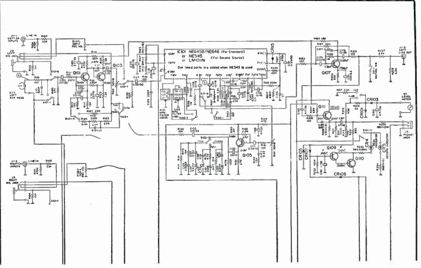
Fig. 7. Complete circuit of a cassette play/recorder unit.
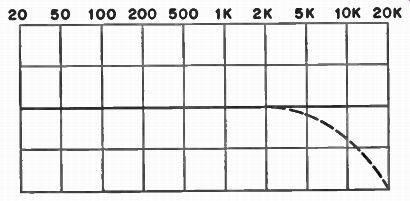
Fig. 8. Passive HI-CUT filter curve.
NOISE REDUCTION SYSTEMS (TAPE RECORDERS)
Noise reduction systems can be divided into two general categories of circuits.
Passive type filters.
Active type (or Dynamic) filters.
Passive Filters
Atypical passive filter circuit will modify frequency response and/or eliminate noise without use of any active devices (such as transistors or IC's). This type of circuit will cause signal level loss between input and output of the filter. Typical examples would include high and low filters which roll-off, or reduce signal level at the high and/or low frequency ends of their response curve. A typical response curve is shown in Fig. 8, where the solid line represents the "wide" high end frequency response of a circuit with the high filter switch in the off position. Reduced high frequency response, shown by the dashed line, occurs when the high filter switch is turned on. While high filters are used to attenuate, or suppress, high frequencies, a low filter system can thus provide the same function at low frequencies. Although these filters are practical, in that they can suppress some noises in a circuit, they will also suppress the level of the desired signals. Out goes the noise, such as tape hiss or record surface noise, and also, out goes the high frequency content of the recorded music.
Single-Ended Noise Reduction Systems (Active)
Typical single-ended noise reduction circuits could be described as deemphasis circuits in which changes of roll-off points and degrees of attenuation vary, based on the levels and high frequency content of a signal. For example, if there is no high frequency content, the response curve will show a reduction in bandwidth. There will also be a reduction in reproduced hiss or related noise (improved signal to noise ratio). Behavior of a typical single-ended circuit can be illustrated as shown in Fig. 9. A high level wide-band signal (Curve A) shows wide band response. As the signal level is reduced, the amount of deemphasis is increased, Curves B, C, and D, respectively. Noise reduction control in single-ended systems occurs entirely during playback. If you reproduce continuous low level, low frequency program material, this type of circuit has a tendency to mute low level high frequencies that may exist in the same program material.
It is possible to process (encode) a signal before recording, and process (decode) it again during playback, in a manner which will improve noise reduction. This can be accomplished by using a compressor/ expander circuit technique and is sometimes referred to as a double-ended noise reduction circuit system.
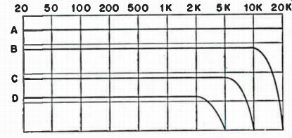
Fig. 9. Noise reduction response curve.
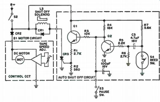
Fig. 10. Auto shut-off tape recorder circuit.
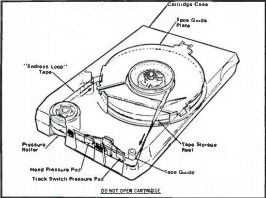
Fig. 11. Inside view of an 8-track cartridge.
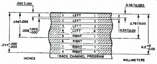
Fig. 12. 8-Track tape format.
AUTO SHUT-OFF CIRCUIT (CASSETTE PLAYERS)
This circuit is used in many various cassette players to shut the machine off when end of tape is reached. A permanent magnet is mounted at one end of the tape counter shaft. On the auto-shut-off circuit board (see Fig. 10) is a magnetically activated reed relay mounted in a position near the magnet on the counter shaft. As the shaft rotates, the magnet will cause the contacts on the reed switch, S4, to open and close. When switch S4 is open, B+ will charge C3, via R7 and R6 to ground. When the switch is closed, C3 will be discharged through R6 and the switch contacts. The Q2 base will see this action as a series of pulses of short duration which will be sufficient to turn Q2 on and keep it on. With Q2 turned on, Q1 will be cut-off, preventing SCR3 from firing and triggering the shut-off solenoid.
When the end of the tape is reached, the counter shaft will stop rotating, reed switch, S4, will stop switching, Q2 base will no longer see the pulses and will cut-off. This in turn will cause Q1 to turn on and current will flow in Ql. Voltage from the tap between R1 and R2 in the emitter of Q2 will be sufficient to forward bias SCR CR3. CR3 will conduct, completing the path from B+, through the solenoid and CR3, activating the solenoid. Solenoid activation causes all mechanically linked levers to go to the off position on the cassette keyboard.
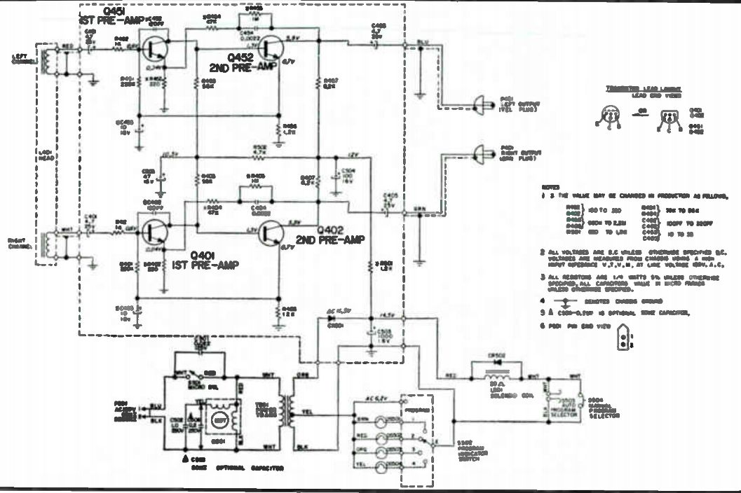
Fig. 13. Circuit for8-track playback unit.
8-TRACK TAPE PLAYER/RECORDER SYSTEM
The 8-track tape units use a cartridge like the one in Fig. 11. The tape is about 0.244 inch, which is slightly less than 1 / 4 inch wide. We see in Fig. 12 the illustration for the track arrangement of a two-channel tape.
As can be seen each track is about 0.022 inch wide, with a guard band of about 0.010 inch between each track. This results in the formation of 4-two-channel programs which are played back as follows.
PROGRAM TRACKS
1 1 and 5
2 2 and6
3 3 and 7
4 4 and 8
Therefore tracks 1, 2, 3, and 4 contain left channel information, while tracks 5, 6, 7, and 8 contain right channel information.
The 8-track cartridge units operate with the tape moving at 3 and 1/4 inches per second. The tape feeds from the center of the tape reel, out to, and past, the tape guide, pressure pads, pressure roller, and back to the outside of the reel. Movement of the tape stops when the cartridge is pulled out of the tape player unit.
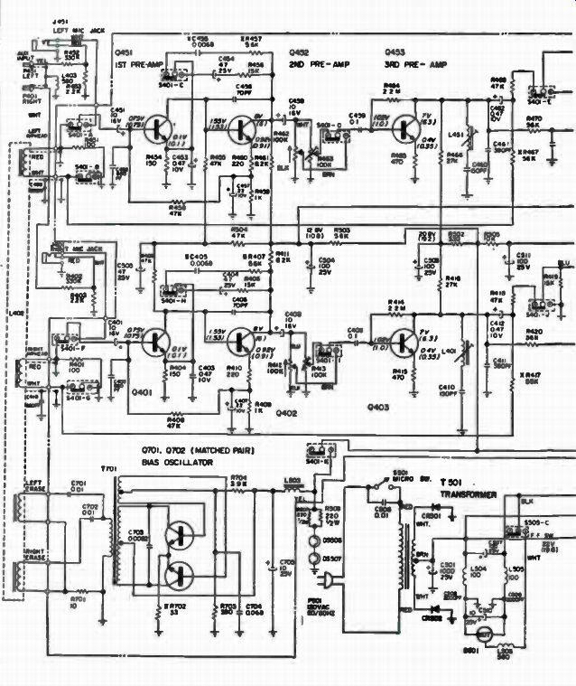
Fig. 14. Complete circuit diagram for 8-track tape player/recorder unit.
Let's now look at the electronic circuit operation for one type of these 8-Track player units. The 8-track players can be grouped into the following systems.
• Playback only.
• Play/Record-Full Feature.
• Play/Record-One Button.
Each unit contains the required circuitry such as a pre-amp circuit for each channel with built-in frequency compensation network to provide the equalization required for proper playback and/or record response.
Two channel (stereo) tape players contain a single circuit board on which the electronic components are mounted. The circuit for an 8-track player unit is shown in Fig. 13. The circuit contains two separate pre-amplifier circuits terminated into two separate outputs for connection to the audio output stages of a stereo power amplifier system.
A full feature 2 channel play/record unit (see complete circuit for this unit in Fig. 14) has the pre-amplifier circuits, VU meter circuit, and bias oscillator module on one circuit board. The bias oscillator is not adjustable and if a fault occurs, replacement of the complete module is required. A second circuit board contains the power supply components and a relay.
The relay, when activated, removes the ground path from the motor and applies it to the ready indicator lamp.
Two channel play/one button record models have a non-repairable bias oscillator unit on the pre-amplifier circuit board. A relay which switches the ground path for the motor to the auto stop indicator lamp is also located on the main circuit board, or on a separate power supply circuit board. Two additional circuit boards, indicator panel wiring and in/out panel wiring, are also mounted within some units.