One of the most important aspects of servicing solid-state audio is an understanding of the methods used to achieve proper biasing of the transistors.
Common methods By now, most of us are familiar with the more-or-less standard transistor biasing arrangements. A few of these are shown and explained in Fig. 1. These circuits, or variations of them, are used in most types of solid-state audio equipment.
Dual-Supply Method
A biasing circuit that is not so universally recognized but is being used more is the dual-supply design shown in Fig. 2. It can be identified by the fact that the ground (or common, if you prefer) is not returned to the positive or the negative side of the power supply. (The circuit in Fig. 2B is a power supply that typically is used with the dual supply type of amplifier.). Instead, in most applications, the ground, which is usually the chassis, "floats" at the electrical mid-point of the two supplies. (However, it some times is designed "closer" to one side than the other, although it usually isn't in audio equipment, because this limits the swing of the output voltage waveform). Increased output voltage swing is one of the advantages of the dual supply circuit. Another advantage seems to be improved thermal stability. This can mean a lot in an amplifier that has marginal heat sinking or that is used inside a closed cabinet. A third advantage is that these circuits tend to be less sensitive to hum pick-up caused by power-supply ripple.
------------------
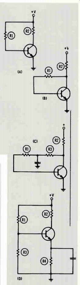
Fig. 1 Common methods of biasing transistors.
A) Fixed-Base-Current Bias--This is the simplest of all bias arrangements, and the most impractical. Bias is established by current flow from the emitter-base junction of the transistor through R1 to the supply voltage. The amount of bias is dependent on the value of R1 and the supply voltage. The primary disadvantage of this bias arrangement is that it provides no means of automatically limiting collector current (stabilization).
B) Collector-Feedback--A simple form of self-bias. Because R1 is connected to the transistor side of load resistor R2, any change in collector current will cause a proportional but opposite change in transistor bias. For example, if collector current increases because of a temperature increase, the voltage at the collector decreases (becomes less positive), which, in turn, reduces the current through the circuit comprised of the emitter-base junction and R1. Al though this bias system does provide a degree of stabilization, it also introduces degeneration, caused by feedback of any AC signal voltage developed across the load resistor.
C) Collector-Feedback With AC Bypassing--This is the same bias system de scribed in (B) except an electrolytic capacitor has been added to filter out, or bypass, AC variations.
D) Combination Fixed and Self-Bias--This configuration provides both good stabilization and minimum degeneration. The fixed emitter-base bias is developed by the voltage divider consisting of R1 and R3. Usually, the valve of R3 is substantially less than that of R1. Resistor R4 performs the function of stabilizing the transistor. For example, if emitter-to-collector current increases because of an increase of temperature, the voltage drop across R4 also increases, placing a more positive voltage on the emitter, which reduces the forward bias on this NPN transistor. The capacitor bypasses AC variations around the emitter resistor, to prevent degeneration. The value of R4 usually is five to ten times less than that of R3.
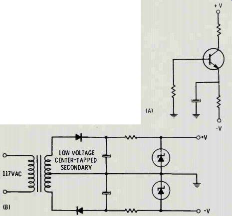
Fig. 2 A) Dual-supply method of biasing a transistor. This method provides
a substantially larger PP voltage swing without significant distortion, and
also offers improved thermal stability. B) Dual type of power supply used with
biasing arrangement shown in (A).
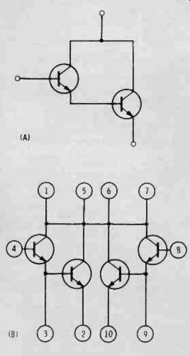
Fig. 3 Darlington amplifiers. A) Conventional Darlington pair. B) Two Darling
ton pairs tied together in an RCA integrated-circuit.
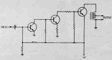
Fig. 4 Single-ended, autotransformer-coupled power amplifier stage without
feedback. Distortion is primary disadvantage of this type of power amplifier.
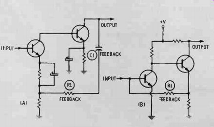
Fig. 5 Two basic types of feedback circuits used in solid-state audio systems.
A Second collector-to-first emitter system. B) Second emitter-to-first base
system.
Feedback reduces or eliminates distortion.
------------------------ Darlington pair
Another type of circuit that is being used more often in solid-state audio equipment is the Darlington amplifier, also called the Darlington pair. An example of this configuration is shown in Fig. 3A. Notice that the collectors of the two transistors are tied together. Also note that the emitter of the input transistor is tied directly to the base of the output transistor. This produces higher current gain and a much higher range of input impedances than are normally possible with bipolar transistors.
Although any two properly selected transistors can be used to make a Darlington pair, it has been the practice of several semiconductor producers to make such pairs available in one package. Both integrated-circuit types and dual transistor types are available. RCA's type CA3036 integrated circuit consists of two Darlington pairs that have all of their collectors tied together. The internal schematic of the CA3036 is shown in Fig. 3B.
Power Amplifier Designs
Single-ended, transformer-coupled
One of the oldest designs of solid state power amplifiers is the single ended, choke- or auto-former coupled type, which, even today, is used in car radios. An example of such a circuit is shown in Fig. 4.
By itself, this amplifier can offer little in the way of decent fidelity.
Add feedback, however, and the situation changes.
Feedback
There are two basic kinds of feedback circuits normally used in consumer products. One, shown in Fig. 5A, is called the "second collector-to-first emitter" system.
With correct values of components, this circuit can make a relatively mediocre amplifier sound like a more expensive one. An open or shorted capacitor or a change in the value of a resistor in this net work will create problems that range from mildly irritating distortion to a runaway condition which can destroy the output transistors. A step-by-step check of feedback components should be performed when ever a "strange" set of trouble symptoms is encountered.
Fig. 5B shows the second widely used feedback system. This one has been dubbed the "second emitter- to-first base" system. This circuit often employs only one resistor to supply feedback voltage.
Push-Pull
The push-pull circuit is widely preferred over other types, for both power-handling ability and overall fidelity. Fig. 6 shows the standard push-pull circuit which has been used in almost every audio application, from 5-dollar portable transistor radios to relatively high priced auto radios and stereo tape players. It is, however, far from efficient when compared to circuits of more recent design.
The circuit in Fig. 7 is a more recent addition to the family of push-pull amplifiers. It often is called the "split-secondary, totem pole" circuit, and is used in many domestic and imported radios, phonographs and tape players. The particular circuit shown in Fig. 7 is from a Motorola console stereo, Chassis HS-2338. The series connection of the output transistors and the split-secondary interstage trans former are the two main identifying features of this circuit.
One thing that all push-pull amplifiers have in common is the necessity of phase-splitting the input signal to provide two signals 180 degrees out of phase to drive the two halves of the push-pull circuit.
In older designs, this was accomplished by either a center-tapped or split-secondary interstage trans former. In many modern designs, the interstage transformer is left out. Although this reduces cost, it does little for fidelity, unless some other means of phase splitting is used.
The transistor phase inverter is one possible replacement for the transformer. These circuits are very similar to their tube counterparts.
They have one driving signal taken from the collector circuit and another, of opposite polarity, taken from the emitter, as shown in Fig. 8.
Another method of providing drive signal of opposite polarity is to use an integrated-circuit pre amplifier which has both inverted and non-inverted outputs. Such units provide push-pull, wide-band outputs from a common input signal. An example of such a circuit is shown in Fig. 9.
Designers have another method of accomplishing phase inversion that often is more economical than either of the methods mentioned above. It is a circuit called the "complementary symmetry" amplifier. This design, shown in simplified form in Fig. 10, takes advantage of the fact that PNP and NPN transistors require signals of opposite polarity to perform the same function. Notice that the bases of the two output transistors are fed in parallel and that the speaker, minus the output transformer, is connected to the midpoint of the two series transistors. Versions of this circuit which use a single asymmetrical power supply usually employ a capacitor to block DC from the speaker circuit. Dual-supply amplifiers might or might not use such a capacitor.
Complementary symmetry circuits do have a disadvantage: It is difficult to locate matched PNP and NPN transistors. Manufacturers "spec" sheets reveal that there are only a few types that can be paired up for complementary service. As the amplifier's power level requirements increase, the number of types from which the designer can choose decreases drastically. The problem becomes even more acute when selecting replacements for such transistors.
It is relatively easy to find matched pairs for low- and medium power complementary circuits. Such circuits are used widely in phono graphs, stereo tape players, auto radios and low-power stereo amplifiers. It is even relatively easy to find matched pairs in universal re placement lines, if the power requirement is only a few watts.
This has led to an interesting modification of the complementary symmetry circuit. The circuit shown in Fig. 11 employs what is known as the quasi-complementary con figuration. In this circuit, the outputs are "totem pole" and the drivers are complementary. For the designer, this means a larger selection of possible power transistors. For the servicer, it means use of a lower-priced line of replacements (less matching necessary).
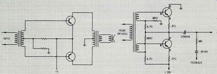
Fig. 6 Conventional push-pull power amplifier. The two in put signals of opposite
phase required by push-pull design are provided this circuit by transformer
action.
Fig. 7 More recent design of push-pull amplifier used in Motorola HS-2338 stereo chassis.
Complementary and quasi-complementary circuits can provide the technician with a new bundle of headaches, if certain precautions are not followed. For example, these amplifiers have some characteristics similar to those of RF amplifiers. One common characteristic is the wide frequency response required of the transistors used for amplification. Because all of these amplifiers are fed very low levels of input signal, extremely high gain is required.
High-frequency transistors in high-gain circuits are quite capable of oscillating at an RF range that extends from supersonic audio to VHF. The result can be a high level of distortion, "lisping", etc. A square-wave test of the amplifier usually will reveal whether ringing or other types of oscillation are present. The visual indication on the oscilloscope screen will be either ringing or a blurring of the trace. Such oscillations can be caused by open capacitors, incorrect replacement transistors or improper lead dress.
General Troubleshooting Techniques
Most technicians agree that the newer circuits are more difficult to service than some of the older designs.
One reason is that many of the newer circuits are direct-coupled.
Another reason is complexity of design.
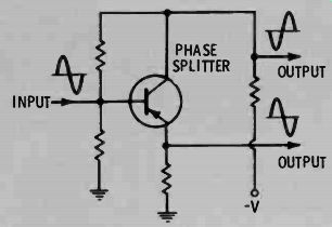
Fig. 8 Phase inverter, which provides two signals of equal amplitude but opposite
phase, replaces interstage transformer between driver and push pull output
stages in some audio amplifiers.
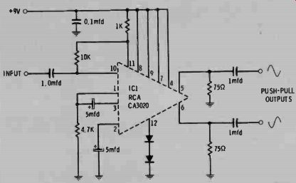
Fig. 9 Equal but opposite drive signals required by push-pull circuit also
can be obtained from an integrated-circuit preamplifier which provides inverted
and non-inverted outputs.
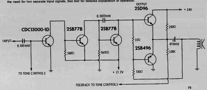
Fig. 10 Complementary symmetry amplifier is a push-pull design which eliminates
the need for two separate input signals. See text for detailed explanation
of operation.
Most troubles, however, can be located within a reasonable time if the technician establishes a routine, logical system of diagnosis.
The first step is a preliminary inspection using sight, sound, smell and touch. Notice, for example, whether any fuses are open or if any fuse resistors show signs of overheating. On many sets, the leads to the emitters of the output transistors serve as fusistors. Notice whether their insulations are charred or melted. Also note whether the printing on any of the output transistors has been erased by heat.
This could indicate which of several transistors is shorted. A transistor that heats up before shorting can often be detected by touch. I occasionally touch several transistors in a single affected section to determine if any of them are heating quicker than the others.
Shorted and leaky transistors cause a large percentage of the difficulties encountered in solid state power amplifiers. One way to locate defective transistors is to measure bias and supply voltages with a VTVM. Generally speaking, though, such tests will confirm only what visual evidence already indicates (burned fuse resistors, etc.). Locating a suitable replacement transistor might take more time than the actual diagnosis. A good rule of thumb is to replace a transistor with an identical type, if the only substitute is from a so-called "universal" line. This advice, in many cases, also applies to using a direct replacement from a manufacturer other than the original.
Always be over-cautious about substitutes. After wading through several large stacks of transistor substitution guides, I have concluded that, in many instances, the people who compile the guides do not even look at the cases of the transistors, much less actually test them. In one incident, I was sup plied with a transistor in a small TO-5 case which, according to the substitution guide, was supposed to replace one in the much larger TO-3 diamond case. Because of the inherent mounting difficulties, there would have been heat dissipation problems. Another time, I was sent a drift-field PNP oscillator/RF amplifier transistor to replace an NPN audio unit. All of these examples involved transistors selected from the replacement guide published by a leading transistor sup plier. Because of these difficulties, I always carefully read the catalogue description of the recommended replacement. If it doesn't meet the most critical characteristics of the original transistor, I do not order it.
Remember, it is no longer true that a mere handful of universal numbers will replace virtually every transistor you will encounter.
Improper heat sinking of the re placement transistor is one of the most persistent causes of premature failure. This causes profit-robbing callbacks, which don't do anyone any good. Careful tightening of the mounting screws and the use of an approved silicone heat-sinking grease will eliminate most heat-sink problems. The mounting screws are especially important on epoxy case power transistors, which recently have become popular in auto radios, phonos and table-model radios.
Many technicians do not make these screws tight enough because they fear cracking the case.
Defective output transistors often cause distortion accompanied by low volume. One way to spot this defect is to measure the DC voltage at the junction where the two output transistors and the output capacitor are connected together.
Compare this voltage to the overall supply voltage feeding that series chain. In most circuits, it should be close to half the total supply voltage. If it is significantly higher or lower, suspect one or both of the transistors.
Unfortunately, many types of distortion are not so simple to locate.
In many instances, a small transistor defect in a pre-driver stage will cause massive bias changes on the output transistors. The complication of DC feedback compounds the difficulty of diagnosing such a defect. A harmonic distortion analyzer can be useful in such situations.
The power ratings on some modern amplifiers are confusing be cause the meaning of "watts" seems to vary from manufacturer to manufacturer. The load impedance of late-model audio amplifiers is often listed along with the power rating.
You might encounter a specification of "fifty watts into four ohms". Such stipulations are necessary be cause the load (speaker) impedance is more dependent on the overall operating parameters than was formerly the case.
Short circuiting the output, or, in some cases, open circuit conditions, sometimes can damage the output transistors. Consequently, be certain that the correct speaker or dummy load is used.
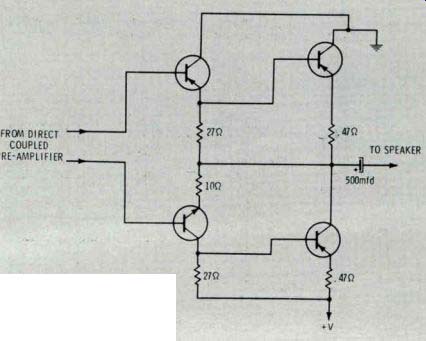
Fig. 11 Quasi-complementary type of audio power-output stage, shown here,
simplifies selection nf replacement transistors.
------------------------