Almost every technician is now, or soon will be, confronted with the problems of solid-state TV servicing. Troubleshooting transistor-TV circuitry involves some new approaches, compared with localizing and repairing tube-type TV circuit defects. The chief reasons for these differences are as follows:
1. DC operating voltages are usually much lower in transistor circuits, than their tube-type counterparts. On the other hand, DC currents may be considerably greater.
2. AC pulse voltages in sweep circuits are generally very low in transistor circuits, compared with tube-type sweep circuits. However, the AC pulse currents are often very large, by comparison.
3. The base of a transistor draws DC current continuously, except in a few specialized cases. By way of contrast, the control grid of a tube seldom draws DC current, except in a few specialized cases. These facts are implied by the statement that a transistor usually has a very low input impedance, whereas a tube usually has a very high input impedance.
4. Because of nonlinear junction characteristics, resistance
measurements are not nearly as useful in analyzing transistor-circuit defects as they are in localizing tube-circuit defects.
5. Transistors are commonly tested in-circuit because they are rarely plugged into sockets, as are tubes.
6. There is considerably more danger of damage to transistors than to tubes in case of accidental short-circuits. The same observation applies to surges resulting from quick tests, such as bridging a suspected electrolytic capacitor by a new capacitor.
7. Test-equipment requirements are different in some cases; for example, a DC voltmeter should have a first range of 1 volt full scale, or less. A capacitor tester must not apply excessive test voltage to electrolytic capacitors. Generators must have blocking capacitors in their output leads.
Comparison of DC Voltage Values The DC voltage values in transistor RF tuners are very different from those in tube-type tuners. Figs. 1 and 2 show the electrode voltages for a 6FH5 tube in an RF tuner, compared with the electrode voltages for a 2SA290 transistor. Note that the plate voltage of the tube is about 80 times as high as the collector voltage of the transistor.
Next, compare the DC voltages at the electrodes of the tube and transistor in the IF stages in Fig. 3.
The plate of the 6BZ6 operates at about 8 times the voltage applied to the collector of the 2SA70. Also, the cathode of the tube operates at about 1/2 of the voltage applied to the emitter of the transistor.
Observe the comparative voltage values shown in Fig. 4. The emitter-follower stage in Fig. 4B operates with a collector voltage of 10.2 volts, compared with a plate voltage of 115 volts for the video-amplifier tube in Fig. 4A. The difference in operating voltages is less in the transistor video-output stage; that is, the collector operates at 90 volts, which is relatively close to the 115 volts on the plate of a video-output tube.
Also note that the picture tubes used in transistor TV receivers generally operate at lower electrode voltages, except that the second anode voltage is necessarily the same for a given screen size.
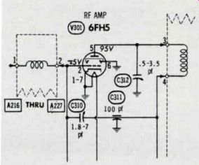
Fig. 1 Electrode voltages In typical tube-television RF amplifier stage.
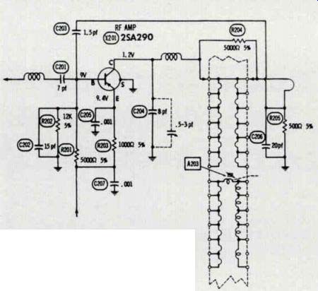
Fig. 2 Electrode voltages in typical transistor-television RF amplifier stage.
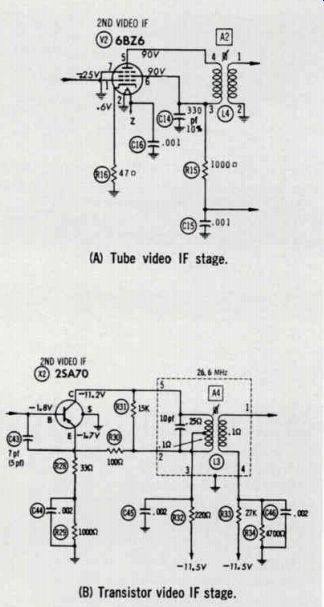
Fig. 3 Comparison of electrode voltages in tube and transistor video IF stages.
(A) Tube video IF stage. (B) Transistor video IF stage.
It can be seen in Fig. 5 that the DC voltages for a transistor keyed AGC stage are quite different from the voltages in its tube counterpart.
Similar differences could be cited for AGC amplifier circuits, horizontal and vertical sync sections, horizontal and vertical oscillator stages, horizontal and vertical sweep systems, and intercarrier sound and audio configurations.
To summarize briefly, comparatively low DC voltage values throughout transistor-TV receiver systems is the main concern. Also, in some cases a low-range DC volt meter must be used; for example, the normal base-emitter voltage in Fig. 3B is 0.1 volt.
Comparison of DC Current Values
As might be expected, a transistor circuit may draw more DC current than a comparable tube circuit. Power is equal to voltage multiplied by current, and if the operating voltage is low, then the operating current must be high in order to produce a given amount of power.
In Fig. 6A, a 6DQ6B tube is used to scan a larger raster, and the cathode current is approximately 130 ma. On the other hand, a transistor is used in Fig. 6B to scan a small raster, but the emitter current is approximately 240 ma.
Another striking example is found in a comparison of transistor and tube-type vertical-output arrangements: The transistor draws 1 ampere of emitter current, whereas a tube in a comparable configuration draws 47 milliamps of cathode current.
Comparison of AC Pulse Voltages
Considering the foregoing examples, it is not surprising to find that AC pulse voltages in transistor stages are usually much smaller than those in their tube counter parts. For example, in Fig. 6B, the transistor driving pulse has a normal amplitude of 6 volts p-p, whereas the tube driving waveform in Fig. 6A has an amplitude of 115 volts p-p.
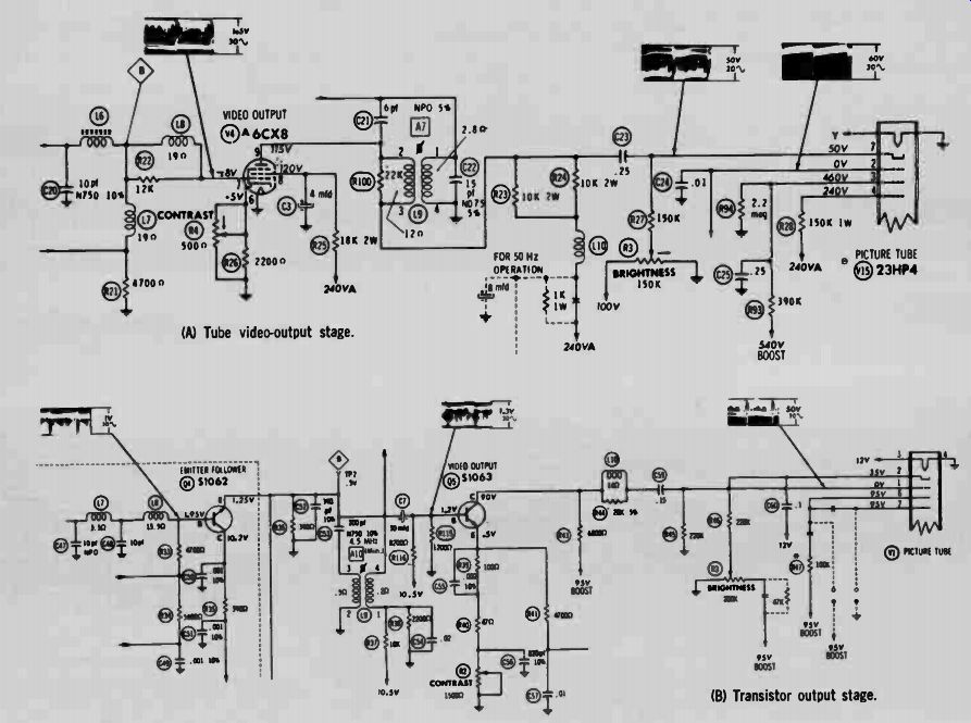
Fig. 4 Comparison of electrode voltages in tube and transistor video-output
stages. (A) Tube video-output stage. (B) Transistor output stage.
Even a greater disparity is found in pulse voltages for keyed-AGC circuits. For example, a transistor is typically keyed by an 8.5-volt pulse, whereas a tube uses a typical keying voltage of 440 volts p-p.
In other cases, AC pulse voltages are about the same in both transistor and tube configurations.
For example, the sync-pulse voltages are approximately the same in Fig. 4. On the other hand, do not suppose that these two video-amplifier circuits operate in the same way. The operating differences can be summarized as follows:
1. Although the control grid of the tube draws practically no pulse current, the base of the transistor draws substantial pulse current.
2. Since impedance is equal to the ratio of AC voltage to AC current, it is evident that the input impedance of the transistor is much lower than the input impedance of the tube.
3. The low input impedance of 05 in Fig. 4B requires the use of a driver stage that can supply appreciable signal current. Therefore, 04 is employed as an emitter-follower (analogous to a cathode follower).
4. In most cases, the output impedance of a transistor is lower than the output impedance of a tube. This is due to the low ratio of collector AC voltage to collector AC current, and also to the comparatively high value of collector junction capacitance.
5. Because transistor junctions have appreciable capacitance, peaking-coil inductances are much smaller in transistor video amplifiers than in comparable tube-type circuits.
Resistance Measurement Difficulties
A tube does not draw current unless sufficient current flows through its heater . On the other hand, a transistor has no heater, and the transistor will draw current when ever a forward voltage is applied across a junction. Because of this characteristic, and because an ohm meter applies voltage to the circuit or device under test, trouble analysis by resistance measurements in transistor circuits is not often practical.
A transistor junction is nonlinear, as depicted in Fig. 7. Because of this, an ohmmeter reading of junction resistance is very unpredictable--we usually do not know exactly how much voltage is being applied by the ohmmeter, nor the exact amount of current that will be drawn.
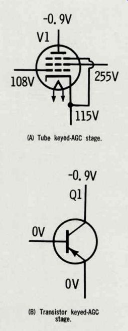
---- Fig. 5 Comparison of electrode voltages in tube and transistor
keyed-AGC stages.
(A) Tube keyed-AGC stage. (B) Transistor keyed- AGC stage.
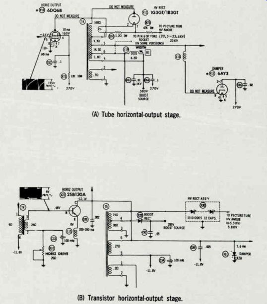
Fig. 6 Transistor draws more current than tube in these horizontal-output
stages.
(A) Tube horizontal-output stage. (B) Transistor horizontal-output stage.
-----------------
Troubleshooting would be simplified if transistors could be unplugged from sockets, as tubes are unplugged. However with few exceptions, it is customary to solder transistors into their circuits, with the result that appropriate test procedures must be employed by the technician to contend with nonlinear junction resistances.
Suitable test methods include:
1. DC voltage measurements,
2. Control-action tests,
3. Signal-tracing procedures,
4. Signal-injection procedures.
DC Voltage Measurements
After picture and sound analysis have localized the cause of a trouble symptom to a particular section of the receiver, DC voltage measurements are the most useful guide in analysis of circuit action and in the pinpointing of defective components.
For example, suppose that sound reproduction is normal, but picture reproduction is poor, with low contrast and a normal raster. With reference to Fig. 4B, these symptoms throw suspicion on the video-output stage. If the emitter, base, and collector DC voltages of 05 do not. measure close to 0.5, 1.2, and 90 volts, respectively, the trouble probably would be found in this stage.
The receiver service data or Sams PHOTOFACT is the best guide in this respect.
Incorrect voltages at the transistor electrodes do not necessarily mean that the transistor is defective; it is also possible that a capacitor is leaky or shorted. Although resistors do not change their values often, this also can happen. There fore, we must evaluate the abnormal DC voltage distribution in an attempt to narrow the number of suspects. Since seemingly logical conclusions are not always absolute, check your reasoning by testing individual components, such as capacitors. In most cases, one end of a capacitor must be disconnected for accurate testing.
DC Voltage Distribution
It is helpful to understand the basic principles of DC voltage distribution in transistor circuits.
For example, Fig. 8 shows an NPN transistor in a typical IF stage configuration. For a better understanding of DC voltage distribution, consider the simplified circuit shown in Fig. 8B. Tabulate the DC voltage distribution in this example:
Emitter-Ground Base-Ground
Collector-Ground 0 volts Emitter-Base -0.2 volt Collector-Base -4.3 volts
One of the most common transistor defects is leakage from collector to base (leakage through the collector junction). In the first analysis, this leakage affects the DC voltage distribution as if a resistor were connected between collector and base, as shown in Fig. 8C. The junction leak age resistance draws current from the voltage divider that biases the base of the transistor, and the base voltage decreases.
This decrease of base-voltage also affects the emitter voltage in the following manner:
1. A decrease in base voltage increases the emitter-base bias voltage;
2. An increase in emitter-base bias voltage causes the collector current to increase;
3. Since the increased collector current flows through the emitter resistor, the voltage drop across the emitter resistor increases;
4. An increased voltage drop across the emitter resistor causes the emitter voltage to decrease.
In the example of Fig. 8C, the 100K leakage resistance between collector and base causes both the emitter voltage and the base voltage to decrease by 0.15 volt. There fore, the emitter-base bias voltage remains unchanged, although the transistor is drawing more current.
If the leakage current becomes excessive, the collector junction will overheat. The transistor then be comes open or shorted, and the stage is dead. Moderate amounts of junction leakage generally cause gain reduction in a stage.
... -4.5 volts
-4.3 volts
MAJORITY CARRIERS
-REVERSE BIAS MINORITY CARRIERS I -CURRENT IRP.) FORWARD BIAS-
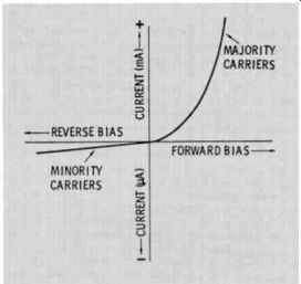
Fig. 7 Plot of current through and voltage across a PN junction.
(B) Equivalent DC circuit.
(A) Typical circuit.
(C) Equivalent DC circuit with collector leakage.
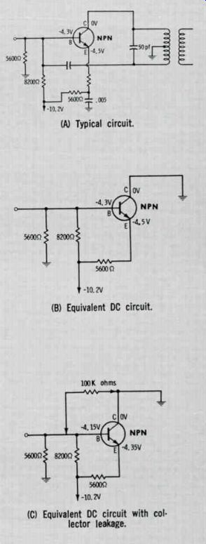
Fig. 8 Transistor IF circuit.
Open and Shorted Collector Junctions
Consider the effects on the DC voltage distribution in Fig. 8B if the collector junction becomes short-circuited. The base voltage will be zero. Since the emitter-base junction has a very low forward resistance, the emitter current is nearly equal to the supply voltage divided by the emitter resistance, or 1.8 ma (in accordance with Ohm's law). The emitter-base bias voltage will rise somewhat above its normal value of 0.2 volt, but the emitter-base junction will not be damaged.
Next, let us suppose that the collector-base junction in Fig. 8B opens up. In this case, the collector current will not load the bias circuit, and the emitter voltage will rise to -6.5 volts. Accordingly, the emitter-base bias will remain normal, and the emitter-base junction will not be damaged.
To summarize briefly, collector leakage or open or shorted collector junctions cause abnormal DC voltage on other electrodes of the transistor. A collector-junction defect causes the emitter and base voltages to be either too high or too low.
Control-Action Test
Control-action tests, also called "turn-on" and "turn-off" tests, are often practical, and are very informative when the normal operating voltages of a transistor are un known. They also can be useful supplementary tests, even when normal operating voltages are known.
"Turn-off" Test
A cutoff, or "turn-off", test is
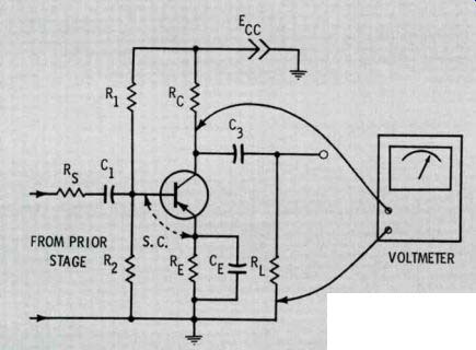
Fig. 9 How to make a cutoff test.
Circuit
-10.1V
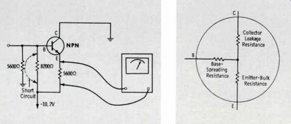
Fig. 10 Cutoff test setup.
Fig. 11 Equivalent circuit for a transistor with collector-junction leakage.
performed simply by cutting off the base current and checking the voltage drop across the collector resistor, or from collector to ground.
For example, to perform a cutoff test of the transistor in Fig. 9, apply a short-circuit between base and emitter. This makes the base and emitter assume the same potential.
This normally cuts off the transistor, causing the collector voltage to rise to the supply voltage, or Ecc, as indicated by the voltmeter.
If the voltmeter does not indicate Ecc in the cutoff test, assume that the collector junction is leaky. Of course, C3 could be leaky, and this possibility must be checked before replacing the transistor.
Next, apply the same basic cut off test to the configuration in Fig. 8A. However, since the circuit does not employ a collector-load resistor, as is obvious from the equivalent DC circuit shown in Fig. 8B, a slightly modified test procedure is employed.
Referring to Fig. 10, short-circuit the 8200-ohm resistor, and check the voltage across the 5600 ohm resistor. Since the collector current is normally cut off in this test, zero voltage normally would be measured across the 5600-ohm resistor. However, if collector-junction leakage is present, a small voltage drop across the 5600-ohm resistor would be measured. The reason for this is seen in the equivalent T circuit for a transistor as in Fig. 11.
If the collector junction leakage is essentially an open circuit (normal condition), no current will flow from the collector into the base spreading resistance and the emitter-bulk resistance. However, if collector junction leakage is measurable, the current flows into the base and emitter branches, and 0.02 volt will be read, instead of zero volts in the test of Fig. 10.
Since it is occasionally necessary to read very small values of DC voltage, a voltmeter with a first range of 0.25 volt full scale will provide maximum utility for the technician.
"Turn-On" Test
A "turn-on" test is another type of control-action test. It is less informative than a cutoff (turn-off) test, because it does not provide an all-or-nothing indication. A turn-on test is a helpful supplement to other tests, as it can confirm prior conclusions.
To understand the turn-on test, refer to Fig. 8B. If a DC voltmeter is connected across the 5600-ohm resistor, the voltage drop, due to collector and base-current flow, will be measured. This is 5.7 volts.
Next, if a 100K resistor is connected temporarily from collector to base, as shown in Fig. 8C, the collector will normally draw more current, and the drop across the 5600 ohm resistor will increase. This is an increase from 5.7 to 5.85 volts, or a difference of 0.15 volt.
Accidental Short-Circuits
Avoid random short-circuit tests, because transistors are easily dam aged. For example, if a clip lead is used in the Fig. 8C test, the transistor would immediately be burned out. Again, if the high voltage is arced in the flyback circuit, it is very likely that the horizontal-output transistor will be ruined. Any short-circuit that causes excessive base-emitter current to flow will burn out the collector junction.
Therefore, avoid surges, which are often caused by shunting a decoupling capacitor or a filter capacitor with a new electrolytic capacitor.
Test-Equipment Requirements
Generators used for signal-injection tests or alignment must have blocking capacitors in their output leads. This precaution avoids disturbance of base-emitter bias voltages because of DC drain-off.
Scopes used in signal-tracing tests should be provided with low-capacitance probes, to minimize circuit detuning.
Capacitor testers must not apply excessive test voltage to the low rated capacitors employed in transistor circuitry.
In-circuit capacitor testers designed for transistor circuits have some degree of usefulness as well as in-circuit transistor testers, particularly when unusual configurations make control-action tests impractical or impossible.
Flyback checkers used in tube circuits cannot be employed in transistor circuits, because the component values and impedances are widely different. However, the same pattern generators and color-bar generators used to test tube-type receivers are used to test transistor receivers. Some modern tube testers also provide transistor-testing functions. However, if your tube tester is conventional, you will need to supplement an in-circuit transistor tester with an out-of-circuit tester. A high-voltage DC probe is an essential accessory for your VOM or VTVM.
Conclusion
We have reviewed the differences between the servicing procedures used for solid-state and tube type TV receivers. These differences are reflected in some of our test-equipment requirements. Transistors cannot be easily replaced, and greater reliance must be placed on DC voltage measurements.
Control-action tests are very useful. Since transistors are more easily damaged than tubes, random short circuits and high-voltage arcing are off-limits. Resistance measurements are less useful in transistor circuits than in tube circuits, due to non linear junction resistances.
The transistor-TV technician needs to have a good working knowledge of Ohm's law, and he can save time if he is familiar with DC voltage distribution in resistive networks.
A VOM is quite practical for nearly all transistor-circuit trouble shooting, because circuit impedances are comparatively low, with very few exceptions.
------------------------