Conventional diodes effectively are voltage-controlled switches. When the anode voltage is made more positive than the "barrier voltage", relative to the cathode, the diode becomes a conductor. Voltages of opposite polarity cause the diode to become an open circuit.
SCR's (silicon-controlled rectifiers) and triacs (see Fig. 1) have more than the one "PN" junction employed in semiconductor diodes. One of these added sections, called a "gate", has the ability to block conduction through the device.
Testing LDR's
The maximum resistance of an LDR can be determined accurately only by maintaining the cell in complete darkness for several minutes before measuring it with an ohm meter. Because many circuits, including the one in Fig. 8, do not utilize the high-resistance characteristic of the LDR, this reading usually is not critical.
The minimum resistance of an LDR can be determined by subjecting it to bright light. A rough test can be made by shining a flashlight at the cell from the same distance each time. I would guess that the LDR shown in Fig. 8 would measure less than 1000 ohms if a 2-cell flash light beam were directed at it from a distance of 2 feet.
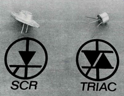
Fig. 1 Shown here are an SCR and a triac and their respective symbols. Note
the physical similarity to transistors.
SCR TRIAC
SCR's and triacs are available in many of the case dimensions and lead arrangements commonly used for transistors. The lead locations of two popular types are shown in Fig. 2. Because this similarity of outward appearance can cause costly mis takes and wrong identification during servicing, tests which indicate whether a device in question is a transistor, SCR or triac will be explained in this article.
Basic Characteristics of SCR's
An SCR can be visualized as a diode in series with a switch, as shown in Fig. 3A. Conduction is controlled both by gate action and by the polarity and amplitude of the anode voltage.
Following are some of the normal responses of an SCR with the listed voltages applied:
• Anode voltage negative relative to the cathode-No conduction, regardless of the voltage applied to the gate.
This is normal diode action.
• Anode voltage positive and the gate zero or negative relative to the cathode--No conduction. This is gate action.
• Anode voltage positive and the gate sufficiently positive- Full conduction. The change from non-conduction to full conduction is a regenerative effect which occurs instantaneously when the gate-cathode voltage is increased slightly above the breakover, or "trigger", point.
• After conduction has started, a "latching effect occurs and the gate loses control and cannot block conduction, which continues until the an ode voltage and/or current are reduced below the "holding" point.
The resistance between gate and cathode of an SCR is about a few hundred ohms. Resistance indications should be similar to those produced by two conventional semiconductor diodes paralleled front-to-back. About the same ohmmeter reading should be obtained when the test leads are switched. Also, the lower the range used, the lower will be the reading obtained. The resistance between the anode and either the cathode or gate should be nearly infinite.
Basic Characteristics of Triacs
A triac effectively functions as two paralleled front-to-back di odes in series with a switch, as shown in Fig. 3B. Some of the responses of a non-defective triac when operated under different voltage conditions are as follows:
• Anode voltage negative and the gate zero relative to the cathode-No conduction. Diode action.
• Anode voltage positive and the gate zero relative to the cathode-No conduction. Gate action.
• Anode voltage negative and the gate voltage sufficiently negative-Full conduction.
• Anode voltage positive and the gate voltage sufficiently positive-Full conduction.
• The change from non-conduction to conduction is a regenerative effect, which occurs when the gate-cathode voltage is increased slightly above the "trigger" point, just as in SCR's.
• After conduction has started, a "latching" effect occurs, in which the gate loses control and the conduction continues regardless of subsequent changes in the gate voltages.
Conduction continues until the anode voltage and 'or current are reduced below the "holding" point.
The junction resistances of triacs are nearly identical to those of SCR's. The gate-to cathode readings should be similar to those produced by measuring two diodes which are paralleled front-to-back. Infinite resistance should exist between the anode and either the cathode or the gate.
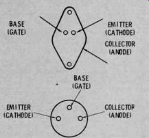
Fig. 2 Because the typical base con figurations of SCR's and triacs, shown
here, are almost identical to those of transistors, specific tests, described
in the text, are required for positive identification.
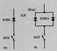
Fig. 3 These circuits illustrate the effective action of SCR's and triacs.
A) An SCR is the equivalent of one diode in series with a switch. B) A triac
is the equivalent of two diodes, connected back to front in parallel, in series
with a switch. When properly triggered on, a triac conducts in both directions.
A Tester You Can Build For Checking SCR's And Triacs
An SCR or a triac should be tested first by use of an ohm meter. An open circuit between gate and cathode, or a short circuit or leakage from anode to gate or from anode to cathode proves the device is defective, and no other testing is required.
Shown in Fig. 4 is a tester which checks SCR's, triacs and power transistors by applying 6 volts DC that is limited to 150 milliamps. This is a good operational test for these devices, and provides the operator visual evidence of SCR, triac and diac triggering and holding actions.
The tests also indicate whether the device is a transistor, an SCR or a triac.
To test an SCR, triac, or power transistor:
• Adjust the polarity switch (S1) to the SCR-NPN position, the toggle type on/off switch (S2) to "off", and the gate-voltage control (R1) to minimum.
• Connect the tester to the device through color-coded clips and test leads.
• Turn the on/off switch to "on". If the bulb lights, the device being tested is shorted, or the test leads are touching.
• Gradually turn up the gate voltage control. At a certain critical voltage (measured by a meter for the most detailed information) the bulb should light, indicating conduction of current through the device.
• A gradual brightening of the bulb when the control is turned up, and a gradual de crease in brightness as the control is turned down indicates that the device is an NPN transistor.
• A sudden lighting of the bulb to full brilliance at one point on the gate-voltage control, and no reduction in brilliance when the gate-voltage control is turned down, indicates that the device is an SCR or a triac. Subsequent tests will determine which. The bulb should remain lit after the control is turned down until a momentary open in S3 extinguishes it.
• Slide the polarity-reversing switch (S1) to the TRIAC-PNP position, and, starting at minimum, turn up the gate-voltage control.
• A gradual brightening and darkening of the bulb when the gate-voltage control is increased and decreased indicates that the device is a PNP power transistor.
• If the bulb does not light when the gate-voltage control is increased, the device is an SCR.
• If the bulb suddenly lights to full brilliance at one position of the gate-voltage control, and the brilliance does not decrease when the control is turned down, the device is a triac.
• Turn the on/off switch to the "off" position, to minimize battery drain.
Tips About Using The Thyristor Tester
The first version of this thyristor tester was designed and built about three years ago, when the RCA CTC40 chassis, which uses two SCR's in the horizontal sweep circuit, was introduced. The original version of the tester used two 67 1/2-volt batteries, a neon bulb, and several more switches to test for leakage, which might occur only at higher voltages. Such a sensitive leakage test was found to be unnecessary and was discontinued in favor of simple ohm meter tests.
Another useful variation of the tester circuit used 6 volts AC for the anode supply, but retained the DC gate-voltage control. A scope connected across the light bulb displayed the cur ret waveform. One difference in operation was readily evident: After the gate-voltage control was turned up enough to light the bulb, decreasing it extinguished the bulb. The reason is that the anode voltage de creased to zero 60 times per second, and unlatching could occur during any of these "zero" times.
An SCR conducts during only the positive alternation of a sine wave applied to its gate, as shown by the current waveform in Fig. 5B. No conduction through the SCR occurred when negative voltages up to -5 volts were applied to its gate.
Triacs conduct during both alternations of a sine wave, as shown in Fig. 50. The crossover type distortion at the mid, or zero, points on the waveform is produced because the voltage must increase from zero to .8 volt DC or more before conduction can occur. Also, conduction ceases during the 0.8 volt DC just preceding zero voltage. Together, these areas of non-conduction caused a measured voltage drop of .6 volt RMS across the triac (from main terminal 1 to main terminal 2).
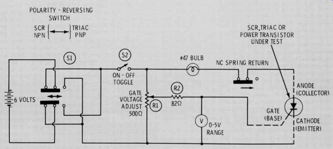
Fig. 4 Schematic diagram of a tester which helps determine whether a device
is a transistor, an SCR or a triac and indicates whether or not it is operating
correctly.
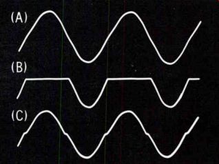
Fig. 5 Waveforms of the load current produced when SCR's and triacs are operated
from an AC anode supply.
A) Waveform of the input 60-Hz sine wave from a heater transformer.
B) Waveform of the current (voltage across bulb) when 6 volts AC was supplied to the anode of the SCR in the schematic shown in Fig. 4.
C) Waveform of the conduction current when 6 volts AC was supplied to the anode of a triac connected to the tester diagramed in Fig. 4. The voltage drop across the triac measured .6 volt RMS.
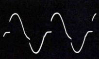
Fig. 6 Partial conduction that occurred when insufficient negative gate voltage
was applied to an SCR of higher voltage rating than the one which produced
the waveform in Fig. 50.
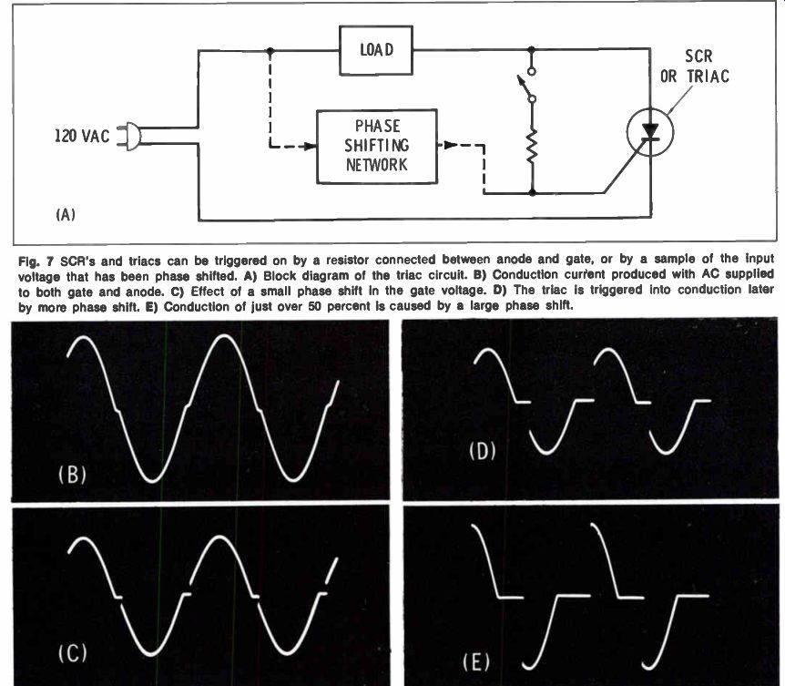
Fig. 7 SCR's and triacs can be triggered on by a resistor connected between
anode and gate, or by a sample of the input voltage that has been phase shifted.
A) Block diagram of the triac circuit.
B) Conduction current produced with AC supplied to both gate and anode.
C) Effect of a small phase shift in the gate voltage.
D) The triac is triggered into conduction later by more phase shift.
E) Conduction of just over 50 percent is caused by a large phase shift.
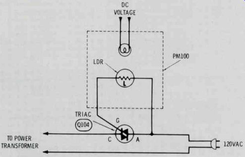
Fig. 8 Remote power on/off circuit of RCA CTC54 color TV chassis. The lamp
is lighted by action of the remote control. The light reduces the resistance
of the Light Dependent Resistor (LDR), or cadmium-sulfide cell; this triggers
on triac Q104, which applies AC to the receiver power supply.
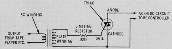
Fig. 9 Schematic of a lilac circuit which will start the change cycle of a
slide projector, or will turn lamps on and off according to the amplitude of
the audio input.
When the gate voltage was positive and the gate-voltage control was advanced very slowly, the triac triggered first into half-wave operation (See Fig. 5B) when the potential on the gate was +0.8 volt. This voltage instantly dropped to +0.7 be cause of the increase in gate current. The gate-voltage control was advanced further and triggering for conduction of both peaks (see Fig. 5C) occurred at + 0.85 volt, after which the gate voltage dropped to +0.4 volt.
These three modes of operation were very distinct, as if a 3 position switch were used. The bulb was unlit, then was lighted to partial brilliance and, finally, to full brilliance, with no variation between.
The action when negative voltage was applied to the gate was somewhat different. Triggering into the full-wave mode occurred at -0.98 volts, which promptly dropped to -0.6. however, there was a tendency for the bulb to light dimly and then brighten. The current waveform shown in Fig. 6 helps explain the reason: Because conduction was triggered on late, during the peak, the bulb was supplied with less total current. Increased gate voltage produced normal conduction.
When tested in the thyristor tester, different brands of triacs with higher voltage ratings required higher gate voltages, than did the smaller sizes. The scope waveforms of the larger triacs generally were less smooth than those produced by smaller ones.
Uses For SCR's And TRIACs
A triac or an SCR can be used to turn on and off resistive loads or to provide variable lighting or motor speed. Two alternate methods of controlling the conduction of these devices are shown in Fig. 7. For example, a 56-ohm resistor connected between the anode and gate will dependably trigger on a triac operated from 6 volts AC. A higher value should be used for 120-volt operation, to avoid gate damage. Use the highest value that will depend ably trigger on the triac.
A variation of this method is employed in the RCA CTC54 color TV chassis, to turn on and off the power to the entire receiver when remote control is used. The circuit is shown in Fig. 8. The remote control sup plies power to the bulb, which is located inside a light-tight assembly. When the bulb is lighted, the illumination decreases the resistance of the Light Dependent Resistor (LDR) enough so that the triac con ducts and applies 120 volts AC to the power transformers.
(LDR's are also called cadmium sulfide cells.) One simple triac-equipped circuit I have used for several years to initiate the change cycle of an automatic slide projector is shown in Fig. 9.
The narration or sound effects which accompany the slide presentation are recorded on one channel of a stereo tape recorder. The speaker is connected to this channel during playback. A short audio tone, of perhaps one second, is recorded on the other channel at any interval where a slide change is desired, so that the narration and the slide changes are in perfect synchronization. The frequency of this tone is unimportant; even 60 Hz is okay. The volume of the stereo unit is at the minimum level required for dependable operation.