Zener diodes are solid-state voltage regulators. They are used often as DC voltage regulators in the voltage supplies to low-level stages in FM receivers and solid-state tele vision receivers, and as the source of a reference voltage in transistor regulated power supplies. Because so many zeners are used in modern equipment, we need fast and accurate methods of testing them, and strong guidelines for selecting replacements.
Zener Diode Actions
A zener diode, when forward biased (anode positive, cathode negative), acts as a normal rectifier diode and provides a low internal resistance. When only slightly re verse biased (anode negative, cathode positive), the diode is nearly an open circuit. This action is identical to that of a normal rectifier diode.
If the reverse bias is gradually increased, as shown in Fig. 1, current flow increases very suddenly at a voltage called the "avalanche" point. A graph of this action is shown in Fig. 2. The voltage at which avalanche takes place is determined by the internal construction and the active materials used during the manufacturing process.
One supply catalog lists general re placement zener diodes with nominal voltages ranging from 3.3 to 120 volts DC. In addition, zener diodes are rated by maximum wattages, which should not be exceeded, if premature failures are to be avoided. A higher wattage rating should not be used for replacement zeners, for reasons which will be given later in this article.
Ohmmeter Tests
Test a zener diode with an ohm meter exactly as you would a power supply diode. The only precaution is that the voltage of the ohmmeter battery should be less than the rating of the diode (most are). Pre-set the ohmmeter for a low scale-we suggest X10-and measure the forward resistance by attaching the positive meter lead to the anode and the negative meter lead to the cathode. A low reading should be obtained. Reverse the diode leads. Any deflection of the needle now indicates a short or excessive leakage. Try a higher scale, perhaps X1000, for a more sensitive reading of the leakage.
If they have previously operated satisfactorily in the circuits under test, most zener diodes which pass this simple test will not be defective.
A more complete test is required to find the operating voltage for a zener, the ratings of which are not known.
A Variable-Voltage Test
Zener diodes for use in experimental circuits or diodes of un known "avalanche" voltage rating can be tested by operation in the circuit shown in Fig. 1. The series resistance (which might, in some cases, be the internal resistance of the power supply) is necessary to prevent overload of the power supply and accidental burnout of the diode under test. The resistor also assures current regulation at the nominal voltage of the individual zener. Replacement zeners are usually available in ±-10-percent or ±-5-percent tolerances.
Connect the zener diode in the correct polarity and increase the supply voltage until a "plateau" is reached, as shown in Fig. 2. The nominal voltage rating is about the center of the plateau. Of course, the current should never exceed the maximum rating of the zener diode.
Many manufacturers test zeners at 20 percent of the rated current.
The diode which yielded the graph shown in Fig. 2 was rated at 4.7 volts and 1 watt. The maximum current was not listed, but was computed using the Ohm's law formula: Power (in watts)=El. Because the power is 1 and the voltage (E) is 4.7, the maximum current (I) is .2128 amps. or 212.8 milliamps.
Twenty percent of 212.8 milliamps is 42.6 milliamps, or approximately 40 milliamps, which should be the test current for the zener used in this example.
If you are testing zener diodes which are original components, the current meter reading can be omitted. Just do not increase the voltage any more than the minimum necessary to establish the plateau.
A fixed power supply voltage and a resistor substitution box or a variable resistor of the proper size to vary the current also can be used to test zeners. However, a smooth variation of current is more difficult to obtain, so this method should The rounded top corners of the waveform in Fig. 4A were caused by the high internal impedance of a one-watt zener diode. Also, the amplitude changed somewhat as the input voltage was varied. When the top corners are rounded, a minimum resistance setting of R1 is recommended, because it sharpens the corners and minimizes amplitude changes. However, the more rounding of the corners, the less accurate the reading of the zener voltage.
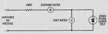
Fig. 1 Schematic of a circuit which can be used to test zener diodes by the
voltage current method.
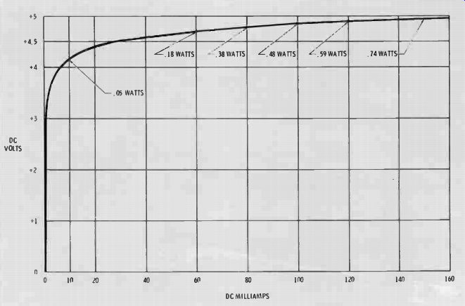
Fig. 2 Results of the voltage-current method of measuring zener diodes can
be graphed. Shown here is the graph of an International Rectifier Z1102-C 1-watt
zener diode. The nominal voltage rating is approximately in the center of the "plateau".
The diode graphed in Fig 2 measured 5.6 volts in the clipping test.
After subtracting 0.7 volt, the corrected zener voltage rating was 4.9 for this diode, rated by the manufacturer at a nominal 4.7 volts. I would rate it from the graph in Fig. 2 as 4.7 volts (the middle of the plateau at 80 milliamps). Rounding of the top corners caused the slightly inflated reading: however, the 4.9 volt reading is more than accurate enough for all normal servicing.
Even more accurate results were obtained during the tests of an exact replacement zener which was rated at 10 volts and 2 watts, although the current/voltage graph showed 8.7 at the usual test current (40 milliamps in this case) and 8.9 at the center of the plateau of the curve. The peak-to-peak reading during the clipping test was 9.7, from which was subtracted 0.7, to give a zener voltage of 9.0 volts.
Although this differs 0.1 volt from the nominal rating obtained from the center of the voltage-current plateau, because of the higher voltage, it is a smaller percentage of error than the error of previous zener diode readings. Also, the amplitude or shape of the corners did not change with variations in R1 or the input voltage.
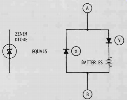
Fig. 3 A zener diode can be visualized as two rectifier diodes of opposite
polarity connected in parallel, with a battery, used to provide a voltage delay,
in series with one of them. Conduction can be obtained in either polarity,
but at different voltages.
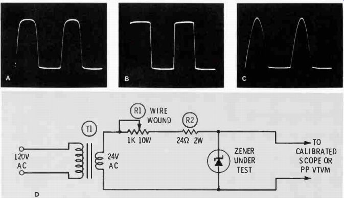
Fig. 4 Waveforms obtained when a zener diode is used to clip a sine wave.
A) The high internal resistance of a 1-watt zener caused rounding of the corners
of the waveform shown here (clipped by the zener action). B) A 2-watt zener
diode, which has lower internal resistance, clipped the sine wave more symmetrically
and gave a more accurate reading. C) A power supply diode clipped just one
peak of the sine wave. D) Schematic of the circuit used to test the zener avalanche
voltage by the clipping method.
We recommend the clipping test to determine the true nominal rating of all zeners of one-watt rating and larger. Remember, the applied AC must be at least twice or more the voltage of the zener that is under test. The values given in Fig. 4D are sufficient for testing zeners up to a rating of approximately 12 volts.
Troubleshooting Zener Regulated Power Supplies
The schematic of a typical zener regulated voltage source is shown in Fig. 5. If the normal load current does not vary excessively and the zener current is near the center of the plateau, the regulation will be adequate for any normal line voltage variation or normal aging of components. However, as practical technicians, we are concerned with the effects and symptoms produced when these components become defective.
When the circuit is normal, an increase of 20 percent in the input voltage to R1 should cause an increase at the zener of about 0.1 volt.
However, the current in the zener might double. There is no certainty that such a voltage increase would cause any of these components to fail, unless the zener current is raised above the maximum rating or R1 is heated enough to cause it to change value.
A lower value of R1 causes the same conditions as an increase in input voltage or line voltage. Such a change, in combination with an actual voltage increase, is likely to destroy the zener (cause it to short). A higher value of R1 decreases slightly the voltage at the zener, but no change in performance should be noticed before the voltage at the zener drops 10 percent or more. At that point, regulation is nearly gone.
An open zener diode will cause an increase in the DC voltage to the load. In some cases, the supply voltage to R1 also will increase excessively and cause problems in related circuits. This can cause serious symptoms, for example, if a voltage to the AGC keyer is changed.
More important, in many cases, an open zener diode regulator can cause a primary symptom of hum or sweep instability because of signal and sweep voltages present on the B+ lines. A zener regulates voltage changes, and hum or sweep voltages on the supply voltage are reduced in the same way DC variations are minimized.
In one circuit, removal of the zener and substitution of a fixed resistor to restore the correct DC voltage increased the hum ripple by a factor of five.
Substitute The Zener With A Resistor
Because a zener is a "resistor" whose resistance changes according to the applied voltage, a variable or selected fixed resistor often can be substituted temporarily for alp be considered a second choice.
Curve Tracer Tests
Tests of diodes and zener diodes using the Jud Williams and Eico transistor curve tracers were described in the March. 1971 issue of ELECTRONIC SERVICING. Accurate results demand that the gain of the horizontal amplifiers in the scope be adjusted to a known calibration.
Zener Tests By Clipping
By bending the truth slightly, we can visualize a zener diode as two rectifier diodes of opposite polarity in parallel, and with a battery, whose voltage is equal to the zener voltage, connected in series with diode "Y", as shown in Fig. 3.
Let's imagine that we connect this zener-equivalent in series with a DC circuit which has 50 milliamps flowing in such a way that terminal "A" is negative. About .7 volt will be measured between terminals "A" and "B", because diode "X" is con ducting and this is the voltage drop across it. Diode "Y" is reverse biased, and, therefore, non-conducting.
Imagine now that the terminals "A" and "B" are interchanged in the circuit. Diode "X" is reverse biased and non-conducting. Because the battery voltage is a constant re verse bias for diode "Y", it cannot conduct until the voltage drop across terminals "A" and "B" exceeds this voltage.
Assuming zero resistance in the battery and a large current, such as 50 milliamps, flowing through the circuit, the voltage drop across terminals "A" and "B" will be equal to the battery voltage plus the 0.7 volt barrier potential voltage of diode "Y". This sum is the zener voltage.
If the analogy stated previously is correct, a zener diode should clip both peaks of a sine wave to produce a square wave whose peak-to peak voltage is equal to the zener voltage plus 0.7 volt (the forward voltage drop). We tested several zener diodes in the ELECTRONIC SERVICING laboratory to verify this assumption, and were pleased with the simplicity of the test and the accuracy of the results.
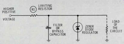
Fig. 5 Schematic of a typical power supply regulated by a zener diode. R1
limits the maximum current which can be drawn by the zener. The voltage across
the load is regulated against input voltage changes or changes of the load
current.
Results of The Clipping Tests
Figs. 4A and 4B show the wave forms produced by two individual zener diodes of different types. The circuit used to obtain these clipped waveforms is shown in Fig. 4D. A good diode which is not a zener produced the waveform shown in Fig. 4C. zener, to prove the condition of the zener. If the circuit functions better with a resistor which has been selected to provide the correct DC voltages, it is likely the zener is defective.
Summary
Four general methods of testing zener diodes have been presented.
These methods include:
• Ohmmeter tests for forward conduction and reverse leakage (fast test)
• Current-vs-voltage measurements (slow but accurate)
• Curve tracer patterns (relatively fast; requires equipment)
• Clipped sine-wave measurements (fast and accurate).
In addition, defective zeners can often be found in-circuit by voltage and resistance measurements, or, when one is open, by the increase in both DC voltage and ripple.
All zener characteristics, except two, can be tested accurately enough, for all practical service operations, by these previously de scribed methods.
There is no easy test to determine maximum wattage, or no convenient rule to specify what wattage zener to purchase for replacement in any particular circuit. Of course, it is best to follow the original specifications when they are known.
Do not replace a zener with another that has a larger wattage rating. It will operate on a wrong part of its curve and cause poor performance.
Internal impedance can be measured, but by a method too complex for service use. If one universal replacement zener fails to operate correctly and all other components are normal, it is possible that the internal impedance of the zener is wrong. Try a different type or brand.