|
|
This section discusses some basic low-power transmitters that use relatively few components. Some simple applications are a wireless microphone, a baby monitor, an FM room "bug," a telephone "bug," and a basic AM transmitter. Note that although these circuits work, they should be considered in the toy class. For any serious purposes, circuits with a few more components and more reliability should be considered. The cost of a small transmitter may not necessarily be too important within reason. For example, the evidence obtained by a small surveillance transmitter might be worth many times its cost. In some cases, the transmitter is considered expendable after it has served its purpose. But for simple experiments, the circuits to be discussed are adequate in most cases. They can be built on perfboard or wired point to point on a piece of copper-clad PC board material, using the components' own leads for support. This approach is known as "ugly bug" construction, which is useful for experimental work and when only one of a kind is needed. Alternately, you could layout and fabricate a PC board if desired.
Wireless Microphone
Probably the most basic transmitter is a simple wireless microphone. This device may be used to connect a microphone to an audio or PA system without the intervening cable, which is a hazard in many situations. The wireless mike is a simple transmitter that acts as a one-way radio link to a nearby FM receiver. The output of the FM receiver then feeds the audio or PA system, replacing the wired microphone. Professional-grade mikes of this sort use a crystal-controlled receiver and transmitter operating outside the FM broadcast band at frequencies specifically intended for this service. (Frequencies around 170 MHz are commonly used for this purpose.) A typical circuit of a wireless microphone is shown in FIG. 1. It consists of an audio amplifier that feeds audio into the bias network of a free-running oscillator circuit operating in the FM broadcast band. An electret microphone feeds audio into audio amplifier stage Q1. R1 biases the mike and may be varied to suit the mike used. This value is normally specified in the manufacturer's data sheet, but 4.7 K is a good "generic" value if no data are available for the microphone. Audio is coupled via C2 to the base of Q1, which is biased by R2, R3, and R4 to about 4 volts and 0.5 milliamps. A low-noise, high-gain audio transistor, such as the 2N3565, should be used, but most high-gain, low-current transistors of this nature should work fine.
Amplified audio at the collector is coupled through the RC network C3 and R5 to the base of oscillator Q2. Q2 acts as a grounded base oscillator, with feedback provided by C8. R5 and R6 provide starting bias for the oscillator transistor, and R7 provides emitter bias.
A VHF transistor, such as a 2N3563, 2N5179, or MPSH10, can be used for the oscillator, and any good 500-MHz or better NPN transistor should work, although the modulation characteristics may vary somewhat. Transistors with larger geometries or lower frequency ratings tend to have larger capacitances, with possibly some what better modulation capabilities, so do not think that a higher-frequency transistor than you really need will perform better. Tank circuit L1 C6, along with stray circuit and transistor collector-to-base capacitance, determines the frequency of oscillation. The collector-to-base capacitance is a function of collector-base voltage, and this voltage is modulated by the applied audio from R5, causing direct frequency modulation of the oscillator frequency. Because the oscillator power out put also varies with collector voltage, some AM component will also be present, but this creates little harm in this application and is the price paid for simplicity. L1 is typically tapped at 10-30 percent total turns from the RF ground end (Vcc rail or C9 in this case). The tap should be as close to ground as possible consistent with good signal output because the closer the tap is to the collector, the more effect the antenna will have on pulling the transmitter frequency. This effect is undesirable and can make the transmitter difficult to set on frequency. C6 is typically a 5- or 7.5-mm polyethylene or Teflon trimmer and is used to set the oscillator frequency. Its value is typically 3-5 pf per meter of operating wavelength.
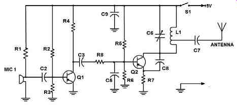
FIG. 1 Typical Wireless Microphone Circuit
Because the FM broadcast band is approximately a 3-meter wavelength (100 MHz), C6 would be approximately 9-15 pf. A 10 pf capacitance would be about right because the transistor and stray capacitances will be approximately 2-5 pf.
Alternately, C6 can be made fixed and L1 varied via a slug or by stretching and squeezing turns, but this technique might be awkward for some applications, so the variable capacitor may prove to be a more practical method of frequency setting. The antenna is usually made about one-tenth of a wavelength at the operating frequency, and at 100 MHz, is about 30 cm (approximately 1 foot) long, but length also depends on application, mechanical constraints, allowable signal strength for meeting legal or FCC regulations where applicable, and the transmitting range desired. C7 is used as a DC-blocking capacitor and is generally around the same value as the tank-tuning capacitor. These values are only rules of thumb and provide working values for components, but final values should be calculated for optimum performance or deter mined empirically on working models.
L1 for the FM broadcast band has a value of approximately 0.25 microhenry and is typically several turns of wire wound on a 1/4-inch coil form, or can even be an air core coil. The coil should be mounted to minimize mechanical vibration and micro phonic effects. A 0.25-microhenry coil with 1/4-inch diameter made from #22 wire has about seven close-spaced turns, and if a smaller coil is needed to save space, 13 turns of 1/8-inch-diameter #28 wire can be used. The tap can be either soldered directly to the coil or a small, twisted loop can be brought out at the correct point.
Alternately, a few turns of wire wound around the ground end of the coil can serve as a secondary winding, eliminating a tap.
The power supply can be a 9-volt transistor battery or six AA cells wired in series, with an on-off switch to control the DC power. Packaging can be almost any suitable configuration, keeping in mind the need for short leads at VHF in the oscillator circuit. The entire circuit could easily be built into a case salvaged from an old defunct microphone from a junked CB set. Your local CB supplier or repair shop will most likely have a bunch of dead microphones lying around, and you could probably have one for the asking.
As for the antenna, for short ranges, up to 25 feet, you might not even need one because adequate radiation from the circuit may occur, especially if you use a plastic case for packaging the circuit. Otherwise, a short length of music wire may be adequate. (Remember to form a loop or install a bead on the end so you don't poke someone in the eye because music wire can be quite sharp.) You could also use a short, collapsible whip of the kind sold for cell phone replacement use.
Tuneup of this microphone is very simple. Power up the circuit and, listening on a blank or unused FM channel in your area, adjust C6 until you hear a carrier in the receiver, as evidenced by a sudden quieting of the receiver noise as you tune C6 to the channel frequency. Speaking into the microphone should produce some audio in the receiver. If not, check your wiring and the dimensions of L1. This may require some cut and try, especially if L1 has been changed in dimensions from those given in the text. If you have one, a frequency counter coupled to L1 will show the transmitter frequency. If you have excessive audio gain, increase the value of R5 as needed. If audio is inadequate, use a more sensitive electret microphone or install a second audio preamplifier stage similar to the stage used in this circuit.
Baby Monitor
The baby monitor shown in FIG. 2 is similar to the wireless microphone but has a second audio stage for more gain. This enables lower room audio levels to be picked up by the microphone. This circuit also has a voltage regulator to reduce the tendency of the oscillator to drift in frequency. The audio stage used is a shunt feed back pair to reduce component count and to provide high gain. The gain of this stage is primarily determined by the ratio of R5 to R3 and is 220 in this example. Q1 and Q2 are 2N3565 or similar low-noise audio devices. DC feedback is provided by R11 from the emitter of Q2 to the base of Q1. R2 biases Q1 and R6 set the bias on Q2. C1 couples mike audio to the amplifier stage. C3 prevents degenerative (negative) feed back through R11 by bypassing any signals at the emitter of Q2. Audio is coupled to the modulated oscillator via C2 and R7. R4 is a gain control and is used to set the optimum value of gain for the application.
The oscillator portion is identical to that of the wireless mike, so we do not discuss it in detail. Note that it is fed DC from a resistor and zener diode regulator, R10 and D1, to supply a constant 9 volts to the oscillator. This aids in reducing frequency drift caused by variations in supply voltage. C5 and C6 are RF bypass and noise-filter capacitors, respectively. Also, an LED D2 is used in series with R10 as a power-on indicator. The LED uses no extra battery current in this manner. The RF components are identical to the corresponding ones in the wireless microphone. The tuning procedure is also identical to that for the wireless mike. Because this circuit will be used in a room where infants and small children are present, it is battery powered for safety reasons.
Use eight AA cells or similar, and because the total current drain is less than 10 milli amperes, battery life should approach 100-200 hours. A power pack made up of eight D cells would last indefinitely long. Use of a wall transformer is not recommended for safety reasons and the possibility of AC hum pickup on the transmitted signal.
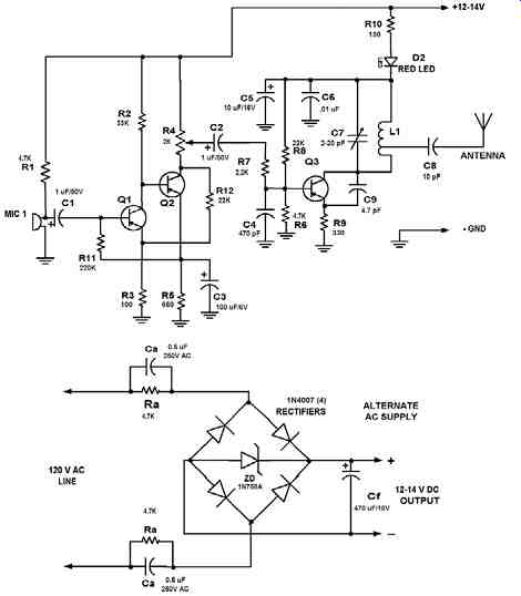
FIG. 2 Wireless Baby Monitor Operating at 88-108MHz
Room "Bug"
The wireless microphone could be built using surface-mount or subminiature components and mounted into a 120-volt electrical box installed in a wall, or even directly on the back of a 120-volt 15- or 20-amp AC receptacle. In this manner, it could act as a room "bug." As shown in FIG. 2, the circuit can be powered directly from the 120-volt AC line by using a bridge rectifier and zener regulator, with capacitors if desired instead of resistors acting as current limiters. Only a few milliamperes at 12 volts is needed. In order to limit fault current, it is a good idea to use resistors (or capacitors) in both legs of the AC line. Capacitors should be about 0.5-1.0 ufd and rated for 250-volt AC service. No antenna is needed because adequate RF is being coupled to the power line by stray capacitance to hear on a nearby FM receiver. For 220- to 240-volt operation, use correspondingly larger resistors and smaller capacitance values. About 0.25-0.33 uf at 600 volts AC rating should be enough for this application. A 470 uf capacitor shunting the zener diode provides filtering of AC hum. The use of capacitors results in lower power dissipation, but capacitor physical size may be a problem, so resistors might be more practical, even with the extra heat generated by them.
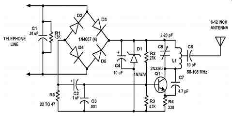
FIG. 3 Telephone Line Bug Operating at 88-108MH
Telephone Line "Bug"
A circuit for a telephone "bug" is shown in FIG. 3. Again, the RF portion is identical, but the method of powering the circuit and the audio input circuitry is different.
This unit is designed to be directly powered by the voltage available from the telephone line, with audio being fed to the circuit directly from the telephone line. How this is achieved can be seen in FIG. 3. The circuit consists of a basic VHF oscillator tuned to a frequency in the FM broadcast band. In most telephone systems, a two-wire loop that connects the subscriber to the central office is used, with the loop current around 20 mA and the loop voltage usually 48 volts DC. When the phone is on the hook, it appears as an open circuit, and the full 48 volts is present on the line.
(The actual voltage may vary somewhat.) When the telephone is taken off the hook, the voltage across the phone drops to a much lower value, around 5-10 volts, and a current of nominally 20 mA will flow.
Superimposed on this line are audio and tone signals. In addition, an AC ringing voltage of around 100-120 volts at a frequency of 20 Hz may be supplied by the central office to actuate the ringer in the phone when a call is received. This "bug" can be placed in series with the hot leg of the telephone line. The DC line current may be used to derive a voltage for powering a small circuit such as the transmitter shown.
R1 and a diode bridge D2 to D5 are inserted in series with the line, ensuring correct DC polarity. R1 shunts excess current around the circuit and passes 8-9 mA, about half the normal off-hook line current. C1 is an RF bypass that prevents strong RF signals accidentally picked up by the phone line from being detected in bridge D2 to D5, and thus appearing as audio on the phone line.
The voltage drop is regulated by zener diode D1 to 9.1 volts and filtered by C2.
R5 is placed in series with the DC supply to sample the audio signal on the line and should be as low in value as possible. Line audio voltage drop across R5 is fed via C2 to the oscillator circuit, which is similar to that used for the wireless mike and is also tuned identically. This voltage causes frequency modulation of the oscillator operating in the 88- to 108-MHz FM broadcast band. Bridge rectifier D2 to D5 causes about a 1.3-volt drop. The total voltage drop from this circuit is 11-12 volts. This is about one-quarter of the available open circuit voltage and should not cause any problems in most instances. This "bug" can be easily detected by a knowledgeable technician because of the high off-hook circuit voltage present on the phone line.
This voltage is approximately 16-22 volts, which is 11-12 volts higher than that normally encountered (5-10 volts); however, this circuit has the advantage of not having a battery that must be replaced periodically. The antenna can be a short (6-inch) wire, or the telephone line itself can be used as an antenna.
Although this "bug" will work and demonstrate basic principles, it is simple and has limitations regarding frequency stability and overall performance. Professional units designed for legal surveillance use by government and law enforcement agencies are generally very small, more complex, and built with surface-mount construction. They feature more sophisticated circuitry and crystal frequency control, and they operate on specially assigned frequencies. They also incorporate features and modulation schemes designed to make their detection more difficult.
Note that laws regulate the use of these kinds of devices, and this information is presented for educational purposes only. It is illegal to eavesdrop on private telephone lines or to use wiretapping equipment on them. The understanding of how these devices work will help in discovering illegally installed bugs on your own or others' telephone equipment.
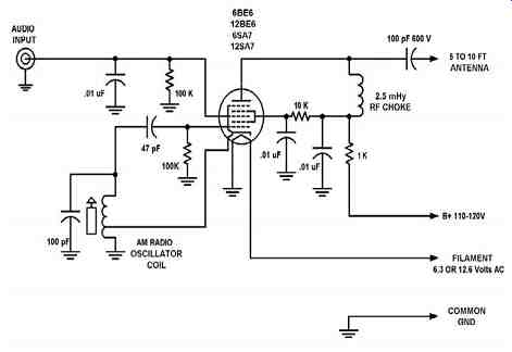
FIG. 4 Simple Vacuum Tube AM Radio Transmitter also Called Phono Oscillator
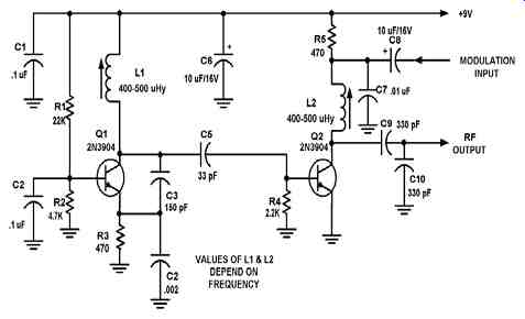
FIG. 5 Basic Low-Power AM Transmitter
AM Transmitter
The final circuit discussed in this section is a simple AM transmitter. This transmitter is basic but allows transmission of audio to an AM radio. It consists of an RF oscillator operating in the AM broadcast band, together with a modulator stage, which mixes the incoming audio and the RF. A signal appears on the output, which has an AM component that can be picked up on a nearby AM radio receiver. In the 1950s, the vacuum tube equivalent of this transmitter was a popular project with electronics experimenters and was known as a "phono oscillator." One such circuit is shown in FIG. 4. If you can find the components, and you enjoy working with old radios and antique electronics, this circuit may be of interest.
It is not critical, and almost any reasonable components can be used.
For most applications, a solid-state battery-powered circuit is preferred. A simple AM transmitter of this type is illustrated in FIG. 5. The transmitter consists of oscillator stage Q1 and modulator/buffer stage Q2. Q1 is biased via R1, R2, and R3. L1, C3, and C4 form the tank circuit with feedback network C3-C4 providing feed back to the emitter of Q1. RF voltage at the junction of C3 and L1 drives buffer/ modulator stage Q2. Q2 is biased by base current produced by RF rectification in the base emitter junction of Q2. C6 is an RF and AF bypass capacitor. C9, C10, and L2 form the tank circuit for the collector of Q2. RF is taken from the junction of C9 and C10 and fed to a short-wire antenna. Audio is fed to modulator Q2 via C8 and isolation resistor R5 and mixes with the RF signal in the collector circuit of Q2, producing a signal that has sum and difference frequencies if the RF carrier and AF input (upper and lower sidebands) along with the carrier signal. An AM signal appears at the collector of Q2. Audio with an RMS voltage equal to about 0.7 times the collector voltage of Q2 is needed for full modulation of the output.
Because of the high level of audio needed, the modulation obtained from this circuit is somewhat limited with conventional audio sources because several volts of audio into a few hundred ohms is needed. The circuit demonstrates the principle of an AM transmitter, however, and with a suitable audio drive level, produces a well modulated AM signal.
L1 and L2 are chosen to resonate with the circuit capacitances of about 150 and 165 pf, respectively, and in the test circuit, inductances of 400-500 micro-henries were used to obtain the desired 600-kHz output frequency, but this circuit can be operated anywhere in the AM band with suitable inductors. For operation at 1500-1700 kHz, for example, adjustable inductors having a range of 50-100 micro-henries would be suitable.
This section has illustrated some simple low-power transmitter circuits that can be built by experimenters in a few hours. These circuits demonstrate some of the principles used in more complex circuits and some of the limitations of simple circuits. Circuits offering a higher level of performance are discussed in the following sections.