|
|
A simple transmitter that enables the builder to broadcast audio through an FM receiver is described in this section. This project is an excellent introduction to low power transmitters and employs no "trick" circuitry. The complexities of a stereo generator and phase locked loop (PLL) are not present, only the "basics," consisting of an audio amplifier and RF oscillator. The transmitter will broadcast over a 50- to 200-foot range, depending on antenna size, and will operate from 9- to 12-volt battery supplies. Although it is intended for mono operation, the same circuitry can broadcast stereo if a stereo generator is used to generate a baseband stereo signal; however, being VFO controlled, it is not really optimum for use with digitally con trolled FM receivers because some frequency drift is inevitable with any free running oscillator. A stability of 100 kHz is about what you will get. Simple analog FM receivers with AFC will easily handle drift of this magnitude. As long as no interfering signals are on-channel, the drift should not be a problem, considering the usual applications of this type of low-power transmitter; however, mono audio will likely not often be used for serious audio transmission to this type of receiver anyway. An ideal receiver for use with this type of transmitter would be a basic analog type, such as an inexpensive personal stereo or a "boom box." This transmitter is also useful for experimenting before committing to a more complex and expensive design.
Often in simple designs, use is made of unpublished or uncontrolled transistor parameters. The variation of collector capacitance with collector voltage is an example. Although it may be specified in curves published by the manufacturer, it is not an "official parameter" specified in the registration of the device. Therefore, other manufacturers' parts may not behave in the same way, even if the device has the same part number, because generally DC parameters, such as hfe and breakdown voltages, and only a few basic RF parameters, may be required to meet specifications for that type. The use of characteristics such as collector-to-base varactor effect, which are aimed at saving cost and simplifying the circuit, may restrict the circuit to one device type and manufacturer, or even a particular device lot. The experimenter who wants to build such a circuit has therefore little chance of obtaining that device, especially if the design is a few years old. The circuit to be described, although a little more complex than some designs for the same purpose, will work with almost any devices and is very forgiving of parts substitutions.
The transmitter is simple enough, with a fairly low parts count, to build on either perfboard or on a piece of unetched copper-clad PC board material using "ugly bug" construction. Although generally unattractive in appearance, point-to-point wiring using a piece of PC board material is simple, and the copper provides an excellent ground plane for the circuit. No time-consuming PC board fabrication step is needed. The circuit can easily be fitted onto a 2-by-4-inch board and can be smaller if desired. The entire finished unit can be housed in a plastic or metal "experimenter's box," which is available from electronics suppliers, or even an electrical outlet box from your local home repair center. Power can be derived from a 9-volt transistor radio battery or from 6 to 8 AA or AAA cells in a suitable holder.
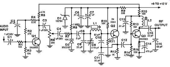
Examining the schematic diagram shown in FIG. 1 shows that the transmitter consists of three stages: an audio amplifier, a voltage-controlled oscillator (VCO), and a buffer amplifier. The audio stage takes the audio input in the 20-15000 Hz range and amplifies it by a factor of about five times, and increases in gain at 6 dB/ octave above 2.1 kHz to add the needed preemphasis to the audio. This audio is fed to a VCO consisting of a Colpitts oscillator with a varactor diode acting as an FM modulator, and the VCO feeds a buffer stage to bring the output up to about 0.5 mW, which will produce a usable signal up to about 200 feet with a short (6-inch) whip antenna. A zener diode provides a fixed 6 volts to the VCO for improved stability with declining battery voltage. Nine to twelve volts is recommended, although the transmitter will operate down to six volts, but the zener regulator will not function properly at this voltage, and more drift may be expected.
Referring to the circuit diagram, audio input is applied at coupling capacitor C1 and ground. Audio is fed through R1 to audio stage Q1, whose gain is determined by the ratio of R4 and R2 to R1. C2 provides bypassing above 2 kHz, reducing the feed back and increasing the gain as frequency increases; this provides preemphasis. R5 and R3 are bias resistors. Audio appears at the collector of Q1, amplified about five times. This audio is fed to gain control R6 through C3, and potentiometer R6 sets the deviation or modulation level. Audio from the wiper of R6 is fed through C4 and isolation resistor R7 to the varactor-modulator diode D2. D2 is reverse-biased through R8 with about 6.8 volts reverse bias. This sets the capacitance of D1 to about 15 pf.
D1 is a 6.8-volt zener diode, with C6 and C7 acting as bypass capacitors to reduce noise and provide an RF ground. The VCO consists of Q2 with associated bias resistors R10, R11, and R12. The VCO is a Colpitts oscillator configuration. This setup has the advantage of reducing the loading on the oscillator frequency-determining circuit by the indefinite and variable transistor parameters, reducing drift caused by the transistor. It is an excellent oscillator when low drift is desired because the transistor input impedance is swamped out by relatively large capacitors C10 and C11.
The series combination of C11, C12, L1, and trimmer C9 in parallel with C8 form the main oscillator "tank" circuit. L1 is adjustable with a slug to set the coarse frequency, and C9 is used for fine adjustment.

FIG. 1 Low Power Vari able-Frequency Oscillator (VFO) Controlled FM
Transmitter
The varactor diode appears in series with C5, and the total capacitance of about 3.5 pf appears in parallel with C8. Adding this 3.5 pf to the 22 pf of C8 and the nominal 6 pf capacitance of C9 (variable from 2-10 pf ) totals about 31.5 pf, which appears in series with the series combination of C10 and C11 (41 pf ). This provides a total effective capacitance of about 18 pf, and L1 tunes with this capacitance. It can be shown that the variation of C10 and C11 caused by the transistor capacitances has only a small effect on the tuned frequency. This contributes to frequency stability.
Audio on D2 varies its capacitance, which varies the capacitance of the tuned circuit, causing frequency modulation of the oscillator, with very little AM component. This will be much smaller than that which would result from modulating the VCO transistor Q2 directly in order to vary its collector capacitance. Oscillator output from a low impedance point (across C11) is fed through C22 to buffer stage Q3. R13, R14, and R16 provide bias for Q3, while R15 suppresses possible UHF self-oscillation in Q3.
C13 is an RF bypass, and the output is filtered by tank circuit L2, C15, and C16. RF output is taken from the junction of C15 and C16 and is about 0.5 mW into 50 ohms.
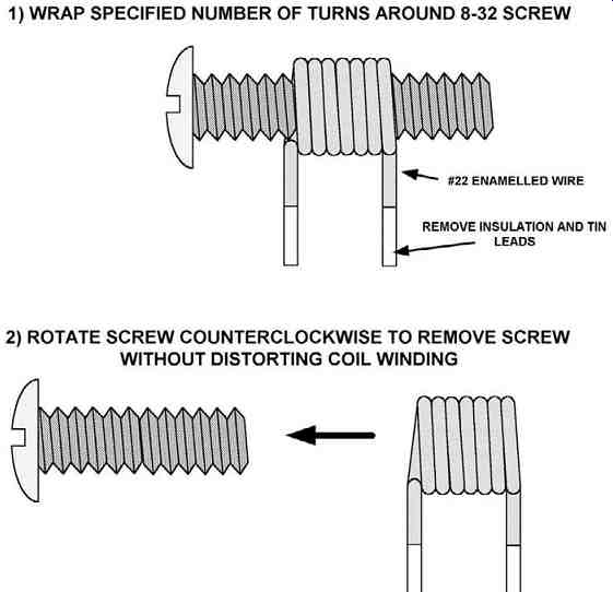
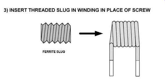
Coil data is given in FIG. 2 for the construction of L1 and L2. They are not critical, and the coils may have to be adjusted later by adding or removing a turn to obtain operation on your chosen frequency. You can find suitable slugs in the IF and video coils used in older TV receivers and junked CB radios. Data shown is for the low end of the FM band (88-92 MHz), where there is apt to be less competition from higher-power commercial stations. Do not operate near and never, never above 108 MHz because you could cause interference with aeronautical navigation systems.
VOR (VHF omnirange) stations operate just above 108 MHz in some areas of the country. Operation below 88 MHz is also illegal and can cause interference with TV reception in areas where VHF channels 5 or 6 are in use. In particular, TV channel 6 audio subcarrier is at 87.75 MHz, which is very close to the FM band. (Many FM receivers can receive this frequency.) In some parts of the world (i.e., Asia), how ever, 76-92 MHz is used for FM broadcasting instead of 88-108 MHz.
In order to check out the circuit, check your wiring, and if it is correct, connect 9 to 12 volts positive to the junction of R5, R9, and R15. First, verify that there are 3.5 volts DC on the collector of Q1, 6-7 volts on the collector of Q2, and 9-12 volts on the collector of Q3. There should be 6 volts across D2; if not, it is shorted or installed backwards. There will be about 0.8-1 volt on the emitter of Q2, and from 2-3 volts on the emitter of Q3. These exact values depend on supply voltage and parts tolerances and are not very critical. Set C9 and R6 at midrange. Do not connect any antenna to C15 and C16 until you have checked out the circuit and set it on an unused FM frequency where you will not bother anyone.
Find a clear channel in the lower end (88-92 MHz) using a receiver on the FM broadcast band. Leave the receiver tuned to this frequency. Power up the circuit and slowly adjust the slug in L1 until you hear a sudden reduction of noise in the receiver (quieting). Use C9 as a fine-tuning adjustment if needed. If no signal is heard, try another higher or lower frequency. Next, apply audio (you can use the line output from a CD player or tape deck) to the input, and you should hear it in the receiver.
Adjust R6 for best sound quality. Although it will be monophonic, sound quality should be excellent. This completes the checkout process.
Mount the transmitter in a case of your choosing. Your local parts house should stock project or experimenter's boxes, or you can use a small metal, plastic, or even wood box from the craft store or home center. The batteries can be mounted in the same case along with an on-off switch and audio input jack.


FIG. 2 Coil Winding for the FM Transmitter
Batteries can be either a 9-volt transistor type or 6 to 8 AA or AAA cells. Use alkaline types because they last longer. We favor AA cells because they last a long time and are often available at low prices. One discount store offers a pack of 40 good-quality name-brand batteries for $7.99, for example. Battery holders are avail able for 6 or 8 cells as needed to fit your case and can be purchased at Radio Shack or one of the mail order houses, or often salvaged from junked electronic equipment. If you wish, you can also wire up an LED power-on indicator, but this will mean a few milliamperes of extra battery drain. A 2.2K or 3.3K resistor in series with a small red LED should provide adequate indication with a 12-volt battery pack.
The antenna can be a short whip (6 inches) mounted to the case and insulated from it if a metal case is used. For short ranges up to 20-25 feet, often no antenna is needed. Keep the range as short as is practical, the signal on your own property, and do not interfere with any commercially licensed station, and no one will complain about interference.
====