Servicing the audio circuits within consumer electronics products is quite simple compared to TV horizontal circuits. Repairing the audio amp stages might take a few minutes longer without a schematic. However, with a few test instruments, simplified instructions, and the test procedures found throughout this section, troubleshooting the audio stages can be easy.
Required test equipment
The following equipment is needed to test audio amps:
- DMM
- Transistor tester
- Capacitor tester
- Signal injector
- External audio amp
- Frequency counter
- Oscilloscope
- Audio signal generator
A good VTVM, VOM, or DMM can quickly locate a defective component with continuity, resistance, voltage, and current measurements (FIG. 1). You need a DMM that takes accurate low-voltage and resistance measurements. Besides voltage and resistance measurements, the DMM might have transistor, capacitor, diode, and frequency ranges. A low audible continuity buzzer is found in some models.
Another important test instrument is a small audio amp. This tester is used to signal trace weak audio signals and distortion found within the audio stages. You can use a mono or stereo amp for signal tracing. In fact, you can build your own audio tester with only a few electronic components (FIG. 2). With these two test instruments, you can locate and repair most audio problems.

FIG. 1 Choose a DMM for accurate resistance and voltage measurements.

FIG. 2 Build a signal-tracing amp with only a few electronic components.
Test records, cassettes, and discs come in handy when signal tracing audio through the various circuits. A simple test speaker, cables, and test clips provide quick audio connections. High-wattage, low-ohm resistors switched in parallel or series can provide speaker loading at the output terminals.
Optional test equipment includes a frequency counter, scope, capacity tester, audio signal generator, audio analyzer, audio wattmeter, wow and flutter meters, and dual stereo signal indicator. Additional audio test instruments are only required with certain audio problems.
The various sound problems
Sound problems include a dead channel and no, weak, intermittent, and noisy sound. The dead-channel or no-sound symptom is easy to locate in the audio circuits. The no-sound symptom can be caused by an open transistor, IC, transformer, or coupling capacitor. Don’t overlook improper or no low voltage from the power supply.
Distorted sound can occur in one channel or both. Very low distortion is difficult to locate. Use a sine- and square-wave generator and oscilloscope to locate a small amount of distortion. Usually distortion occurs in the audio output stages. Distortion can be caused by leaky transistors, ICs, coupling capacitors, a change in resistance, or burned bias resistors.
Weak, intermittent, and noisy sound is more difficult to locate. Weak audio can be caused by open capacitors, a change of resistance, leaky transistors, ICs, or bias resistors. Locate the weak stage with an external audio signal and voltage and resistance tests.
The intermittent or noisy sound symptoms must be located by eliminating each audio stage. A low frying noise can be caused by a leaky transistor or IC. Ceramic by pass capacitors in the front end of the audio circuit can produce a low hissing noise. Signal trace each stage until the intermittent component is located. Just about any component within the audio circuits, including poor PC board connections, can cause intermittent sound.
Ears for a day
When servicing audio circuits, your ears are king of the day. You can hear distorted, weak, or no audio within the speakers. You can hear a popping or frying noise caused by a defective transistor, IC, or ceramic bypass capacitor. Often, the frying noise is a constant low-level noise that can be heard all the time in either or both speakers. A popping noise can result from a defective output transistor or IC component.
A weak stage within the audio circuit can cause unbalanced channels. Often, the volume must be turned up on the other channel to compensate for a weaker channel. If a dual-volume control is used in the audio circuits, the weak stage must be located and repaired. Check for small defective electrolytic coupling capacitors and a change in bias resistors within the weak circuit (FIG. 3). The unbalanced channel can be checked with a scope or external amp and test (3 kHz) cassette, within the cassette player.

FIG. 3 Use your ears and a few test instruments to locate the defective
part in the audio circuits. Output
Servicing the small phono amp
The audio circuits within small inexpensive amps consist of three or four transistors or a couple of IC components (FIG. 4). In the latest phono amps, one large IC might be found. Digital and larger phono turntables are switched to the same stereo amplifier as the cassette deck and the AM-FM-MPX receiver.

FIG. 4 Only three transistors and coupling transformers are found in the
early phono amp. Crystal cartridge
The small phono amp can operate from batteries or a separate power adapter. Weak batteries produce weak and distorted sound. Likewise, improper voltage applied to the audio circuits can produce the same results. Don’t overlook a cracked or old crystal cartridge when weak sound is a problem.
Dead, no sound
Schematics for low-price phono amps are very difficult to locate. If the phono amp is battery operated, check the batteries. Measure the dc voltage applied to the audio output transistors. Usually, the two output transistors are mounted near the driver and audio output transformers in a transistorized circuit. Clip a speaker across the suspected speaker to test it.
If there is still no audio, rotate the volume control wide open and touch either lead removed from the crystal cartridge. You should hear a loud hum. If a hum occurs, suspect a defective cartridge.
Because you don’t know which terminal you are taking voltage on, write down each voltage measurement. The highest positive voltage should be the collector terminal on an NPN transistor. Likewise, the highest negative voltage should be the collector terminal of a PNP transistor. The two low-voltage terminals should be the emitter and base terminals. A low resistance measurement from common ground to the transistor terminal indicates the emitter lead.
Measure the voltage between the two unmarked terminals of the lowest voltage. If the measurement is 0.3 V, the transistor is a germanium type with a high negative collector voltage. An NPN transistor will have a 0.6 V between the base and emitter terminals with a higher positive voltage at the collector terminal (FIG. 5). Usually the transistor is good if it has these voltage measurements.
Distorted sound
Go directly to the audio output transistors or ICs with distorted sound. You might find only one large IC in the latest phono amplifiers. Place the metal tip of a screwdriver blade on the top of the volume control or crystal cartridge. You should hear a loud hum with distortion. If there is only a hum, suspect a defective crystal cartridge. Substitute another speaker to test the suspected speaker.
Take critical voltage measurements on all IC terminals (FIG. 6). Notice if the supply voltage is very low. This voltage should be close to the battery or adapter voltage. Suspect a leaky IC component. The supply terminal should have the highest voltage (3 to 12 V).
Apply an audio signal from the signal generator on all terminals, and notice if distortion can be heard on any of them. If you measure a low voltage at the supply terminal and the output signal is distorted, the IC usually should be replaced.
Weak sound
Inject an audio signal at the volume control, and determine if the sound is normal. Check the audio output coupling capacitors and ICs for weak conditions. Insert an external audio generator signal on both sides of the capacitor. Go from the base to the collector of each transistor with injected signal. Apply external audio at the in put and output terminals of the IC for a loss of audio.
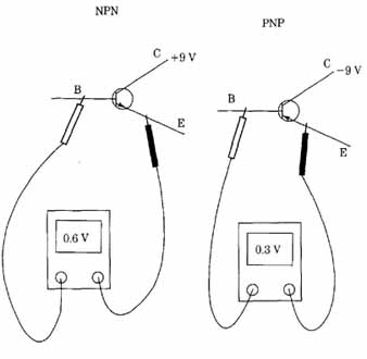
FIG. 5 The PNP transistor has a 0.3-V bias between the emitter and base,
while the NPN transistor has 0.6 V.

FIG. 6 Take critical voltages upon each terminal of amp IC to locate a
defective IC.
Repairing the audio amp
Today’s electric clock radio and small portable radio amplifier circuits consist of transistors or ICs. IC components are found in radios with AM-FM-MPX stereo and cassette players. Transistors were found in inexpensive early portable and table model radios.
The typical transistor audio circuits consist of three transistors, with two in push-pull operation and the other as a driver or AF transistor (FIG. 7). Often the driver is an NPN type, while the output transistors consist of NPN and PNP transistors. The sound signal can be directly or capacity coupled in the output circuits.

FIG. 7 A driver and two transistors in push-pull operation in the radio
amplifier.
Distorted sound
Check the two audio output transistors for leaky conditions within the circuit. Remember, when diodes or low-ohm resistors are found in the base circuits, the measurements might not be accurate. Remove the base terminal for accurate transistor tests. Very low voltage measurements on all transistors can indicate a leaky transistor.
Often both output transistors are found close together and have separate heat sinks. If in doubt, locate the large coupling capacitor to the speaker, then trace the positive end of the capacitor back to the output transistors. Another method is to eliminate the driver transistor by tracing the small coupling capacitor back to the base terminal.
Mushy sound
Suspect the small speaker for mushy or distorted sound. If a headphone jack is available, insert the phones and check for mushy audio. Replace the speaker if the headphones sound normal. Remove one speaker wire, and clip a good speaker across the terminals.
Dead, no sound
Inject an audio signal at the center terminal of the volume control to determine if the audio output circuits are normal. If there is weak or no sound, proceed to the input terminal of the IC. When a schematic is not available, try several different terminals. Trace the PC board wiring from the volume control through the coupling capacitor to the input terminal (FIG. 8).
If there is no signal at the output terminal, suspect a defective IC, surrounding components, or improper supply voltage. Take voltage measurements on all terminal pins, and write them down. The highest voltage is usually the supply voltage. Compare this voltage with the total battery or power supply. Measure the dc voltage across the largest filter capacitor and compare.
No audio can be caused by an open speaker. Clip a good speaker across the suspected one. Don’t overlook large speaker coupling capacitors for open or intermit tent conditions.
Cassette amp repairs
Small cassette players might have three or four transistors, one large IC, or a combination of both. Cassette deck audio circuits might consist of several IC components or a combination of transistors and ICs. For example, the equalizer or pre amp tape head stages might consist of two transistors or one IC in a stereo audio circuit.
Power amp

FIG. 8 Suspect a defective IC when there is signal in (2) and none at output
(6).
Look for a transistor within the recording bias oscillator circuits. Transistors can be used as AF or driver stages, while the latest stereo cassette decks might have several IC components. The audio output stage can be one large IC for both stereo channels or separate ICs (FIG. 9).
Distorted left channel
If the right channel is normal and the left channel is distorted, go directly to the audio output IC. Try to locate the audio stages by looking for power ICs on heat sinks. You might find more than one heat sink, indicating separate audio output circuits. Sometimes both output ICs are mounted on one large metal heat sink or chassis (FIG. 10).
You can compare voltage and resistance measurements within the stereo circuits against the defective channel. Often the left channel components are on the left side when looking from the front of the cassette deck. At other times, they are not in line but are placed in a group of ICs, transistors, and decoupling electrolytic capacitors.
After locating the audio components on the PC board, take critical voltage measurements or inject audio signal into the audio circuits. Start at the center terminal of the volume control. Apply external audio signal at each IC pin. When on the good channel, you will hear a loud tone in the speaker. The other IC output component is the distorted one. If you don’t have an audio or sweep generator and don’t plan to purchase one, build a 1-kHz tone generator with parts found at Radio Shack (FIG. 11).
Distortion can be caused by a leaky IC, a change of resistance, or open or leaky bypass capacitors. Check each resistor tied to the power IC terminals and compare them with the normal channel. Shunt each bypass or electrolytic capacitor or IC terminal to check for distortion. Check for high leakage across each capacitor terminal.

FIG. 9 There might be only one large IC in the small cassette player.

FIG. 10 A large IC might contain both audio amp channels.

FIG. 11 Build a 1-kHz audio signal generator with one IC and six parts.
Noisy sound
Notice if the sound is present when the volume control is turned down. If not, the noise is created in the front end of the audio circuits. Transistors and IC components can cause a low frying noise in the sound. Locate the noisy components by inserting a signal from a signal tracer or amp to the base terminal and then the collector of each audio transistor. When the noise is heard on the collector terminal and not on the base terminal of the same transistor, you have located the noisy transistor.
Likewise, signal trace the noise at the input and output terminals of ICs to locate a noisy IC. Sometimes applying coolant to the body of an IC can cause the noise to increase or go away. Heat applied from a hair dryer or heat blower might increase the noise. Replacement of the IC is the only answer.
Warbling or squealing noises in playback mode can be caused by a dirty or worn function switch (FIG. 12). Spray cleaning fluid into the switch area. Work the function switch back and forth to clean the contacts.
Dual IC amp
In the small audio amp, you might find one large dual IC or two separate ICs upon a heat sink (FIG. 13). Today, one IC might be found in the audio stereo output circuits. The dual IC contains both input and output circuits. A separate pre amp IC driver stage might amplify the audio for the output circuits, while, in other dual IC circuits, the AF and audio output circuits are contained in one IC.

FIG. 12 Clean the function switch by spraying cleaning fluid down inside
the switch area for intermittent, noisy, and warbling sound.

FIG. 13 A dual IC or separate ICs might amplify the audio output sound.
Often, the dual volume control rotates the input audio to terminal pins 3 and 13 (FIG. 14). A dirty or worn volume control can produce intermittent or a scratching sound in the speaker. Check the small 1-uF electrolytic capacitors for a weak or unbalanced stage. Check all electrolytic capacitors under 10 uF. The audio output pins of IC 106 are 7 and 9. Two 1000-uF electrolytic capacitors couple the audio from each channel output to the speaker jacks. Pin 8 supplies 15.5 V to IC106.
A defective dual-power IC can produce weak, distorted, or dead audio or weak audio with distortion in both channels. You might find only one channel distorted or weak while the other channel is normal with a dual-power output IC. Suspect the power output IC when both audio stages are defective. Also, check pin 8 for the voltage supply source. Improper supply voltage can result in weak audio in both stereo channels.
Signal trace with test cassette
The 1- or 3-kHz test cassette can be used to signal trace a defective audio stage in the cassette player. Simply insert the test cassette, and use the scope or external amp to signal trace the weak, distorted, or intermittent audio channel. Start at the volume control, and work either way or at the tape head. Usually, the audio circuits are laid out with the audio transistor or IC pre-amps in line with the correct output circuits.
Defective left channel IC

FIG. 14 Dual 1C106 contains the left and right stereo audio output channels.
By going from base to base of each audio AF or driver transistor, the volume should increase as you proceed through the audio output circuits (FIG. 15). Check on each side of a coupling capacitor for weak audio reception. When the stage be comes weak or distorted, check the proceeding circuits. Locate the base and collector pin terminals and test for audio. When the signal is weak at the collector compared to the base terminal, suspect that transistor or components within the circuit.

FIG. 15 Signal trace the cassette audio circuits with a test cassette,
scope, and external amp.
Very weak sound
The sound was very weak in the left channel of a J.C. Penney cassette player. After cleaning the tape head, the left channel was still weak, while the right channel was normal. Signal injected at the volume control of each channel was normal, indicating the weak stage was in the tape head pre-amp IC.
IC5 was located with signal injected at the right tape head and on terminal 1 of the IC. The sound was weak at coupling capacitor C79, coupling the tape head sound to the AF circuits. Check the audio tone on each pin of the IC of the good channel. Accurate comparison tests of the two channels will indicate the defective stage (FIG. 16).
Tape head

FIG. 16 Open capacitor (C75) caused weak sound in a J.C. Penney 1783 cassette
player.
To amp
IC5 was suspected of open conditions. Voltage tests on the right and left channels of 1C5 were fairly normal. Although very weak audio was found at pin 3, all resistors and capacitors that were tied to the IC were checked. Capacitor C75 was found to be open. It is wise to check all the components tied to the pins of the suspected IC before replacing the IC.
Blown speaker fuse—JC Penney 3223
The speaker fuse might blow or open when dc voltage is found upon the speaker connection, when the transistor output is unbalanced, and when too much volume is applied to the speakers. A speaker fuse is inserted to protect the speakers from voice-coil damage. High volume placed upon the speaker can damage the voice coil and blow it loose from the speaker assembly (FIG. 17).
A leaky transistor can upset the balanced output and apply dc voltage directly upon the speaker terminals. The speaker voice coil becomes warm and is frozen against the magnet pole piece. This cannot occur in audio circuits with large electrolytic coupling capacitors. The dc voltage is isolated from the speakers. Some directly connected amps do not have a speaker fuse or blocking capacitor, resulting in damaged speakers.

FIG. 17 The speaker fuse can open with extreme volume, unbalanced amp circuit,
and dc voltage applied to the voice coil.
Before installing a new speaker, always check the speaker terminals for a low dc voltage. Do not install another speaker, or it can be damaged at once. Turn the volume way down, or insert a 7.5-a 10-watt resistor across the speaker terminals to act as a speaker load (FIG. 18). Now measure the voltage across the resistor. Zero voltage should be measured across the speaker terminals. If voltage is found, repair the audio output circuits before damaging another speaker.
Loud hum: blown fuse
One of the main fuses was blown in a Pioneer SX-950 amplifier. FU2 (1 amp) fuse was black inside the glass area of the fuse. After replacing the fuse, a loud hum was heard and the chassis was shut down. Most line fuses are caused by leaky audio output transistors and ICs, and one transistor was found leaky.
A quick test of the bridge rectifier circuits indicated normal positive 50.7 V and a high negative —64.5 V (FIG. 19). Two voltage regulator transistors were found in the negative power source. Both transistors were tested in the circuit, and a 2SA720 transistor appeared open. The transistor was removed and tested again. After re placing Q1, the negative power source returned to —50.7 V.

FIG. 18 Place a 7.5-a, 10-W resistor across speaker terminals for test
purposes.
FIG. 19 An open (2SA720) regulator transistor in the negative voltage source
increased voltage to —64.5 V.
Car radio problems
Fifteen years ago, transistors and IC components were found in deluxe AM-FM MPX stereo car radio audio circuits. You might find one large IC as pre-amp for the cassette tape head circuits, pre-amp IC audio, and power output transistors (FIG. 20).

FIG. 20 One large pre-amp IC contains both stereo tape channels.
Today, IC components are found in most audio circuits of the common car radio. Besides IC components, processors and surface-mounted parts are found in car receivers. In fact, several layers of PC boards must be removed before getting to the audio board (FIG. 21).
Dead right channel
Locate the dead channel with either an external audio amp or an audio genera tor. Start at the volume control and work both ways through the circuits. Besides defective transistors, ICs, and capacitors, check for defective speakers and wiring in the dead channel. Often, a low hum can be heard in the speaker with no sound, indicating the amplifier circuits are defective. Don’t overlook a dirty function switch, burned voltage-dropping resistors, or leaky coupling capacitors.
Place a cassette in the tape deck and signal trace the audio through the various circuits. Compare each signal with the normal channel. Shorted output IC components will show signs of operating warm and might have burned or stripped PC board wiring going to the supply terminal. An overheated power IC can indicate a leaky IC or burned bias resistors.
Both tape head channels distorted
Suspect a dual pre-amp, leaky IC, tape heads, switching, or common power source when both channels are distorted. If only one large IC is found as the power output in lower-priced amps, take critical voltage measurements on each IC terminal.
Often the IC power components are mounted on a heat sink or metal radio chassis. Sometimes these power ICs have heat sinks bonded right to the component.
The dual IC amp is located on the PC board. Look for this IC with other audio components. If in doubt, look up the IC part number (on top of the IC) and cross-reference the part number with the semiconductor replacement guide (FIG. 22). The guide will indicate the exact replacement and what stage it works in.
Intermittent right channel
Make sure the intermittent right channel is in the speakers or radio. Clip an out side speaker to the intermittent channel. Suspect a poor PC board connection or a cracked board. Sometimes parts will break loose or vibrate from the PC board. Try to isolate the intermittent section within the audio section with signal tracing.
With intermittent sound problems, more time is required to locate the defective component. Sometimes coolant sprayed on the parts within the intermittent channel can make parts act up or quit. Lightly pushing on small components with a pencil or pen can cause the intermittent to occur. Twisting and moving the PC board can isolate the intermittent to a certain section on the board. Don’t overlook worn volume controls, poor soldered connections, and cables when intermittent sound is a problem.
Popping and cracking sounds
Suspect the output power IC, module, or transistor when popping or cracking noises occur. Sometimes these power ICs will pop and crack while music is playing and then become intermittent. Locate and signal trace the popping noise with an external speaker amp. Spray coolant on the suspected component and see if it quits.

FIG. 21 Several layers of PC boards might have to be removed to get at
the audio hoard.
Very loud whistling and howling from the speaker can be caused by a defective filter capacitor. Shunt a similar capacitor across the suspected one and notice if the noise disappears. Tack the capacitor in with the power off. Howling can result from a red-hot leaky output IC. An annoying hum can be caused by leaky ICs or transistors. A leaky or dried up filter or decoupling electrolytic capacitor can cause a hum in one or both channels.
Unusual dead left channel
The left channel was dead with only a low hum in a Sanyo FTV92 car radio. With a cassette playing, sound was signal traced at the dual volume control (VR1-E). No sound was found at the volume control of the left channel (1) and normal channel (2) (FIG. 23). This means that the suspected component is ahead of the output circuits.
Although some signal was heard ahead of R44 (3), why was there no signal at the top or center of the volume control and loud music before R44? A resistance measurement between the center terminal and ground indicated a direct short. VRE-1 was shorted internally and replaced with the exact part number.
Red-hot transistors
Audio output transistors that are too hot to touch can be leaky or shorted. In the car radio, audio output transistors are mounted upon a large heat sink or chassis. remove the suspected output transistor, and test out of the circuit. Suspect directly coupled transistors of being leaky or open. Test all transistors in the directly coupled circuits. While the transistors are out of the circuit, inspect and measure the resistance of the bias resistor. Often, bias resistors are burned or overheated with leaky output transistors.

FIG. 22 Check the part number on top of the IC, and cross-reference in
the universal semiconductor guide for the correct replacement.
Likewise, when an auto receiver with a loud hum and red-hot IC is found, suspect a leaky output IC (FIG. 24). Sometimes the PC foil and “A” lead might be over heated and burned with leaky output transistors or ICs. The supply voltage source can be low with leaky output components. Check all resistors and capacitors tied to each IC pin for leakage or a change in resistance.

FIG. 23 The unusual dead left channel in a Sanyo FV92 car radio.

FIG. 24 1C107 operates too warm and was found leaky.
Stereo amp repairs
Usually stereo amps are easy to repair, because one of the channels might be normal and can be used as a reference. The channels are systematically laid out for location of components when servicing without a schematic. Voltage, resistance, and signal tests in the normal channel can be compared to the defective channel (FIG. 25).

FIG. 25 The electronic technician checking the diodes iii the bridge circuit
of the high-powered amp.
Higher-wattage amplifiers might have transistors or ICs in the output circuits. These components are located on a large heat sink or metal chassis. Often the bias resistors and decoupling capacitors are found close by (FIG. 26). The AF, driver, and pre-amp stages are found on a separate board or are mounted ahead of the power output components.
No left channel
Signal trace the audio at the volume control. If the signal is normal on both channels, proceed to the output transistors. Inject an external audio signal into the base terminal of each output transistor or the input terminal of the IC, and listen for a tone in the speaker. The audio signal on the output transistor will be low when normal. The audio should be high at the input terminal of the power IC when normal.
Proceed toward the driver and pre-amp stages with the signal injection methods. Likewise, audio signal can be checked with a cassette tape or with the unit turned to radio in the AM-FM-MPX receiver. Use an external test amp for the latter method of signal tracing.
Check the left channel speaker for open connections. An open driver or AF transistors and IC pre-amps can cause a dead channel. Don’t overlook open or dried-up electrolytic coupling capacitors. Leaky decoupling capacitors can open voltage supply resistors with no or improper voltage at the audio circuits. Often, leaky or shorted output transistors and IC components will have weak and distorted sound.
Both channels distorted
When both channels are distorted in a stereo amp, look for something in common with both channels. A dual stereo power input or output IC can become leaky and cause distortion in both channels. Improper voltage from the power supply circuits can cause distortion. Either negative or positive voltage sources can cause distortion in both if one voltage is missing. Dirty or corroded function switches can apply incorrect voltage to the audio section, causing distortion.
Distorted right channel
Go directly to the audio output transistors or ICs for extreme distortion in the audio (FIG. 27). Locate the distortion in the right channel by checking each output transistor with a signal tracer. Keep the signal tracer amp volume as low as possible. Likewise check the input terminals of each power IC for distortion.

FIG. 26 large IC mounted upon a heavy heat sink combines both audio channels.
Distortion in the audio output components is often caused by leaky transistors or ICs, burned bias resistors, leaky bias diodes, and improper voltages. Look for a change in the bias resistors or blown electrolytic or coupling capacitors. Small, corroded screwdriver-adjusted bias resistors can cause distortion.
A leaky power output IC can cause distortion in a given channel. Burned bias resistors or leaky driver and Darlington transistors directly coupled to the output IC can cause distortion. Signal trace the audio through each stage until the distortion clears up, then take voltage and resistance measurements. Always check bias resistors when a leaky IC or transistor has been removed from the circuit.
Keeps blowing fuses
Blown speaker fuses can be caused by too much power applied to a set of speakers. A defective or grounded voice coil can open the fuse. The speaker fuse might keep blowing if a leaky component in a directly coupled amplifier is applying raw dc voltage to the speaker fuse (FIG. 28). Always check for dc voltage at the speaker terminals before connecting another speaker; otherwise, the speaker and fuse might be damaged.
Keeps damaging the power output IC
After a new power IC (STK-0050) was installed iii a large Pioneer amplifier, the IC became warm and extreme distortion was noted before the replacement was destroyed (FIG. 29). DC voltage was found on the right speaker terminals. R263, a 0.22-ohm resistor, was found burned and was replaced. When the right channel IC was defective, the circled voltages (see FIG. 29) were found on the terminal pins.
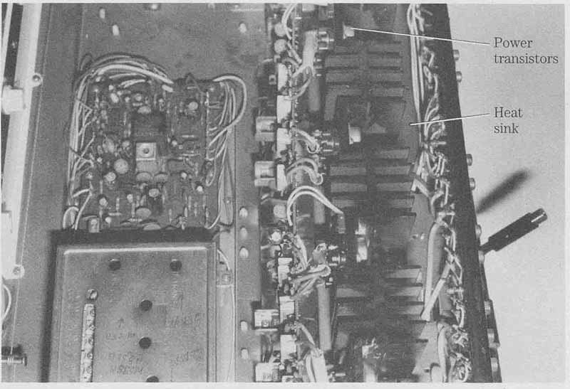
FIG. 27 Check for leaky and open output transistors for weak and distorted
sound. Power transistors; Heat sink.

FIG. 29 Leaky driver transistors keep destroying the large output IC in
a Pioneer amplifier. Bold voltages when defective.
All driver transistors connected to pins 0 and 1 were tested in the circuit, Q11 and Q13 indicated leakage. Both transistors were removed and tested. Because Q13 was directly shorted, both transistors were replaced. At the same time bias resistors R257 (510 k-Ohm) and R259 (200 Ohm ) were checked. R259 had changed resistance and was replaced. Zero voltage was found on the speaker load resistor (10 ohm, 10W), indicating normal sound, after replacing the power IC (STK-0050) with an original re placement, Q11, and Q13 and resistors R259 and R263.
Troubleshooting CD player audio circuits
Signal trace the audio from the output of the digital-to-analog (D/A) converter IC through the sample hold IC and audio amp to the line output jack with an external audio amp. The stereo audio circuits begin at the output terminals of the D/A converter stage. Usually the audio amp in both channels is found in one IC component. Determine if the trouble occurs in the CD player or the sound amp connected to the line output jacks (FIG. 30).
If one channel is normal and the other is dead or distorted, use the good channel for voltage and reference measurements. Check the sound at points 1 through 4 (see FIG. 30) to locate the defective component. Check the input and output signal of each IC. When the signal becomes weak or distorted in the external amp, you have located the defective stage.

FIG. 30 Check by the numbers when signal tracing the audio circuits in
a CD player. Bold voltages when defective
Distortion can be caused by one positive or negative voltage missing from each IC. Start at the audio line output jack, and locate the audio amp IC. Backtrack signal tests until you hear sound in the external speaker. Don’t overlook a defective mute switch transistor. Usually the emitter terminal of the mute transistor is at ground potential. Remove the emitter terminal, and notice if the audio is now present at the line output terminal (FIG. 31). Take voltage measurements on the stereo amp, and compare both channels.
Distorted right channel: headphones
In a Realistic 42-5029 compact disc player, the right channel was distorted with weak sound. The headphones were replaced with another pair, and indications were the same. The right headphone circuit was traced from the headphone jack back to a small 10-ohm resistor and a 220-uF coupling capacitor (FIG. 32). The electrolytic coupling capacitor was found connected to pin 10 of a dual output IC. The voltage supply pin measured 1.7 V.
New batteries were installed, and the results were the same. Audio was signal traced into pin 3 of IC going to the volume control with distorted output at pin 10. The volume was up and normal in the left channel. IC was replaced, restoring normal CD headphone reception.

FIG. 31 Suspect mute transistors with no sound on the line output jacks.

FIG. 32 Leaky IC1 caused a weak and distorted right cha in headphone circuits
of a Realistic 42-5029 CD player. Headphones
Servicing the TV audio amp
Sound symptoms in the audio output stages can include no, intermittent, weak, muffled, distorted, and noisy sound. Try to locate the sound discriminator coil and audio output IC. Often the IC is located close to the shielded discriminator coil assembly (FIG. 33). Several audio amp ICs in the TV chassis have their own heat sink on the PC board. Another method is to signal trace the speaker wires back to the audio output circuits.

FIG. 33 Locate the shielded coil of the discriminator, and adjust for clean
audio. Discriminator shielded audio coil.
Distorted sound
After locating the discriminator coil, lightly touch up the core until the sound is clear. Sometimes weather changes or extremely wet weather can cause the coil frequency to change. If the sound needs to be adjusted again, and the coil is off-frequency, suspect a small ceramic bypass capacitor within the coil circuit.
Extreme distortion can be caused by a leaky audio output IC or components. Take critical voltage measurements on each IC terminal. Check each component that ties to ground. Look for open electrolytic capacitors or resistors in the IC circuits. Check for leaky audio output transistors and bias resistors that could cause distortion.
Hum in the sound
Check for poor ground connections within the pre-amp audio stages. A low hum can be caused by dried-up decoupling capacitors and a loud hum by open main filter capacitors. Check for a defective IC or audio output transistor when a low hum occurs.
In a General Electric AC-B chassis, a low hum was heard with some distortion. The hum noise acted like a pickup hum in a microphone. Finally R175 was located as the cause of the low-hum symptom off of pin 15 of the sound IC (FIG. 34).

FIG. 34 Hum was caused in a GE AC-B TV with open resistor R175. Bold voltages when defective
Intermittent and weak sound
Weak and intermittent sound can be caused by defective transistors, ICs, and open electrolytic coupling capacitors. Signal trace the in and out of each component. Replace the suspected IC or output transistor if the sound coming in is normal but weak sound is found at the output terminal. Don’t overlook a defective speaker-coupling capacitor for weak and intermittent sound (FIG. 35). Clip in another speaker to determine if the speaker is normal.
Popping noises
Look for defective audio output ICs or transistors when popping and snapping noises occur. Sometimes the popping noise occurs after the TV set has warmed up.
Apply coolant on the suspected component to see if the noise disappears. Signal trace the noise at the input IC terminal or the base of the transistor with the external amp connected. If the noise is traced to the output component, replace it.
No audio
Because the Goldstar CMT2612 set had stereo sound, several different stages of audio must be found upon either the main chassis or separate PC boards. The left channel was dead with a normal right audio channel. Because most sound problems occur in the audio output circuits, the speaker leads were traced back to P903 on the TV chassis. Nearby was a large IC mounted upon a large heat sink. At the other end, another power transistor was mounted.
The audio was signal traced with the scope, on input pin 2 and output pin 12 of the right channel. Pin 7 of the left channel was connected to a 470- electrolytic capacitor. Audio appeared normal at pin 7, which no doubt was the left output pin terminal. A scope test on both sides of the electrolytic capacitor was normal and found no sound at the speaker. The speaker wires were traced to P903 and to an external- internal switch. When the ohmmeter lead was touched upon the switch, the left audio channel was normal. A poorly soldered connection upon the switch terminal caused the left audio channel to go dead (FIG. 36).
Audio distorted
The sound was distorted and weak in a Sharp portable TV. The speaker wires were traced back to a speaker-matching transformer from two small audio transistors in a push-pull circuit. Next, four small transistors were located toward the transformer. Besides an output transformer, high voltage was found upon the audio output transistors.

FIG. 35 Intermittent, weak, and no sound can be caused by a defective electrolytic
coupling speaker capacitor.

FIG. 36 A poor contact on SW031 resulted in no left channel audio in a Goldstar CMT-2612.
The base emitter and collector voltages were high in both transistors, indicating a leaky directly coupled transistor. Both transistors were removed, and the NPN transistor indicated leakage (FIG. 37). While out of the circuit, a driver transistor tested normal. Although the PNP transistor tested good, it was replaced with an ECG32 universal replacement, and the NPN was replaced with an ECG31. Remember, these two transistors operate in a higher-than-normal voltage output audio circuit.

FIG. 37 Replace both audio output transistors in the Sharp 19SB6OR portable
TV for distorted audio.
Servicing high-power amps
The very high-power amps (100 to 1000 W) contain flat gold contact areas for maximum current handling conditions. Total amperage with individual amps can exceed 1750 A. Each stereo section is lined up with gold-plated, solid-copper bar strips down the center. The power output ICs and transistors might have extra heavy heat sinks or outside chassis heat sinks. Each stereo or mono amp might have its own power supply, removing channel-to-channel interaction and crosstalk.
High-speed switching FETs supply input power to the power toroids, keeping RF from entering or exiting the power amp supply. Fast-switching diodes might be found in some units. High-powered Darlington and triple Darlington output devices are found in some output stages.
Usually high-powered output stages are in line and easy to locate. Audio signal tracing methods can locate most defective components. Check for burned boards, flat bar connections, and burned toroids or resistors that might indicate leaky components. Compare the good channel with the defective one. Separate high-powered mono amps can be checked against a normal one.
Transistor and diode tests within the circuit can locate an open or leaky component. Actual voltage tests on power ICs can determine if an IC is leaky. Compare the voltage and resistance tests of a suspected component against the good channel. Substitution of high-powered ICs and Darlington transistors might be necessary after signal tracing the audio to the defective component.
Always replace high-powered amp transistors, ICs, Darlington transistors, FETs, and toroids with the exact part number. Remember, these are special parts.
Power output resistance measurements
After testing diodes and transistors in the circuit, take critical resistance measurements on the output ICs and transistors to common ground. This test can help locate defective transistors, FETs, and IC components that break down under load. Connect a speaker bank-load of resistors across the defective speaker terminals, especially in directly coupled circuits. The output voltage at the speaker terminals should be zero in directly driven circuits.
When the directly driven circuits have dc voltage at the speaker terminals, suspect a leaky or shorted component in the audio output stages. With a power load connected to the speaker terminals, the resistors might run warm but will still give the technician time to make some tests. This will prevent voice-coil speaker damage. Just connect the high-wattage resistance load to the speaker terminals.
Resistance measurements within the audio output circuits can uncover the defective component, especially when the unit keeps knocking out fuses or destroying output ICs or transistors. Make resistance tests of each transistor or IC terminal to common ground. Compare each measurement with the good channel.
The VTVM or VOM works best in resistance tests because electrolytic capacitors will charge and discharge. It takes time for the numbers to count down or add up with a DMM. Of course, the DMM is far more accurate in these tests. Write down each resistance measurement for comparison.
When you find a big difference in resistance measurements, the defect is in that circuit. Often the power ICs or transistors have been replaced and the trouble still exists. Sometimes voltage comparison tests might not show the defective component, but accurate resistance measurements within the circuit can indicate problems.
===Audio amp troubleshooting chart===
Check the power amp troubleshooting chart shown in Table 1.
Table1. Power amp troubleshooting chart. (match Trouble number with Remedy number)
| Trouble | Remedy |
|
|
. ===