Today, the auto receiver has many new features, including a digital varactor and quartz tuning, AM/FM preset stations, Dolby B and C, auto reverse cassette player, CD and trunk changers, and a very high-powered amplifier. The car radio has made drastic changes since tubes and vibrators were king. Besides a cassette player, the auto receiver might have a CD changer control with the changer located in the car's trunk.
You will find many integrated circuit (IC) components doing double duty within the new auto receiver. One large IC might contain the front-end section, whereas one or two output ICs may be found in the audio circuits. Silent switching is now accomplished by using fixed diodes instead of a manual function switch. Several different printed circuit (PC) boards are found throughout the cramped spaces. Now a few surface-mounted devices (SMDs) can make the auto radio smaller physically (Fig. 1).
Required test instruments
The following equipment is needed to test car radio circuits:
1. Digital multimeter (DMM) or voltmeter
2. Transistor tester
3. Radiofrequency-intermediate frequency (RF-IF) signal generator
4. Sine- and square-wave generator
5. Oscilloscope
6. External amplifier
7. Frequency meter (optional)
8. Audio analyzer (optional)
9. Equivalent series resistance (ESR) meter
The power supply
When the car radio is pulled from the dashboard, a bench power supply is required to provide a 12- to 14.4-V source in servicing the receiver. A low-priced power sup ply with a 13.8-V supply at 7 A can be purchased for less than $50. The variable 3- to 15-Vdc supply at 12 A may list for $150. When servicing those old car radios and high-powered amplifiers, choose a 30- to 40-A heavy-duty power supply. The vari able regulated power supply with 0 to 24 Vdc is ideal for powering most electronic products (Fig. 2). Try to choose a variable power supply with voltage and current meters.
The front-end radio section
The front-end section of the latest auto radio might consist of an FM and AM tuner, an intermediate frequency/multiplex (IF/MPX) unit, an IF counter, a central processing unit (CPU), and analog switching. The AM tuner might have a radiofrequency (RF) transistor in the antenna circuit, RF and IF coils, ceramic stages, and oscillator circuits. Varactor diodes tune the RF and oscillator stages with a variable voltage (VT). One large IC might provide circuits for the RF, IF, and oscillator circuits (Fig. 3). The tuning voltage is controlled by a CPU IC. Locate the front-end circuits by themselves or from the antenna receptacle.
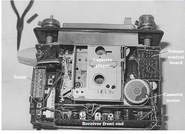
FIG. 1 The early all-transistor car radio and cassette player had electronic
components cramped on different PC boards.
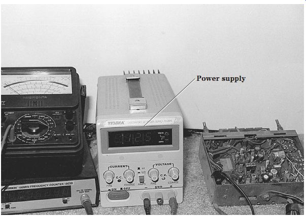
FIG. 2 A bench power supply with a digital meter is a must item in servicing
auto receivers on the service bench.
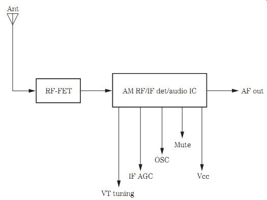
FIG. 3 The front-end AM section of an auto receiver might have an RF FET amp
and an RF/IF detector IC.
An RF transistor or a field-effect (FET) transistor amplifies the weak antenna signal to a tuned coil within an early car radio. Suspect a defective RF transistor when only one AM local signal can be heard. Measure the voltage on the RF transistor terminals. Test the RF transistor with a semiconductor test or the diode tester of the DMM. Likewise, test all RF and oscillator transistors with voltage and semiconductor tests.
The rear section
The rear section of a low-priced auto receiver may consist of an audio section, cassette player input circuits, CD player circuits, power supply, and AM/FM silent switching. A dual IC may be found in the cassette input circuits. The CD output circuits may feed to the stereo line output jacks or into a large power amp circuit (Fig. 4). You may find one large output IC with muting transistors that feed to left and right stereo fader speaker controls. Often the high-powered amplifier may contain 20 or more output transistors.
Start at the volume control center terminal or a test point on the external amp, using an audio signal generator to signal trace the audio circuits. The sine- or square wave generator can determine if distortion is found in either stereo audio channel.
Connect the signal generator to the RF or IF section to signal trace the front end. Injecting signals from a white noise generator can trace signals in both the RF and audio circuits.
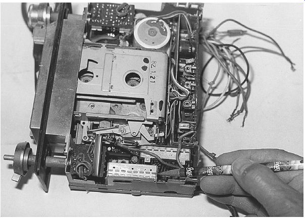
FIG. 4 An early auto radio might have a varactor tuning section and stereo
audio circuits.
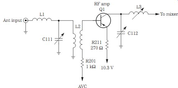
FIG. 5 The very early car radio front-end stages are tuned with variable capacitors
C111 and C112.
Variable-capacitor tuning
You might find in the early car radios a variable-capacitor tuning component. The antenna receptacle picks up the radio signal from the outside car antenna. The variable capacitor tunes the RF coil before the radio signal enters the base terminal of the RF transistor. Here the RF tuned signal is amplified and applied to the convertor stage.
The converter or oscillator transistor selects the AM station and is combined with the RF signal within the converter stage. A variable capacitor tunes the RF, converter, and oscillator stages (Fig. 5).
Check the RF transistor for a weak or lost radio station. Sometimes only a strong lo cal radio station can be heard when there is a defective RF stage. A broken antenna wire off the loading coil can cause a loud rushing noise with no tuned-in stations. Peek at the antenna coil for broken wiring. If a station fades out with a scratching noise, suspect that one or two plates of the capacitor are touching one another. Squirt a lubricating oil into the variable-capacitor rotor bearing when there is noisy tuning operation.
Inductance tuning
A variable-inductance or permeability tuner is the result of a powdered iron slug moving inside the RF, oscillator, and mixer coils. Permeability tuning was designed to take the place of ganged variable-capacitor tuning. These coils are wound with very fine wire, and as the tuning iron slug moves into the coil, a ganged tuning assembly moves the slugs in and out of the different coils.
Most problems with permeability tuning involve a dry gear assembly, broken wires on the coil winding, or poorly soldered connections, causing intermittent reception. A bro ken wire on the RF coil can cause no or only a local radio station to be tuned in. A broken slug inside the oscillator coil can cause stations to shift as the auto hits bumps. Poorly soldered connections or old soldered joints can produce intermittent reception (Fig. 6).
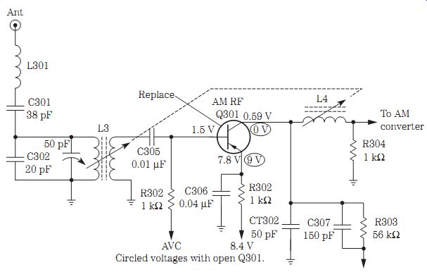
FIG. 6 Only a local FM station could be heard in a Craig 3521 radio with open
Q301.
Varactor tuning
Varactor tuning involves a varactor diode that changes capacity when a dc voltage (VT) is applied to it and is used to select broadcast stations. When the tuning system supplies voltage to the varactor diode, a different station is tuned in. Just by checking the different voltages on the varactor diode, you can determine if the tuning system or the RF, oscillator, and mixer stages contains the defective parts (Fig. 7).
In the Audiovox AV-215 with an FM station tuned in at 92.1 MHz, the control voltage is 2.1 V. This voltage increases as stations are tuned higher in the FM band. At 88 MHz, the voltage is 1.5 V, and at 108 MHz, the voltage is 5.5 V. In the AM band at 530 kHz, the voltage is 0.99 V, and at 1400 kHz, the tuning voltage is 5.83 V. This voltage will vary somewhat in different car radios.
When no tuning voltage is found at the varactor diodes or controlled transistors, check the CPU PLL processor. Measure the supply voltage (Vcc) on the supply pin. If voltage is supplied to the varactor diodes without any stations tuned in, suspect problems within the front-end circuits instead of the CPU quartz or digital synthesized circuits.
Check the supply voltage on the suspected PLL or CPU processor.
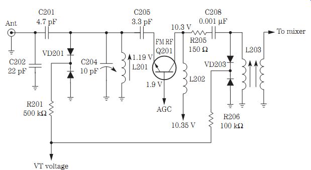
FIG. 7 Improper varactor diode voltage (VT) caused the stations to fade out
in a Ford D7AF (19A241AB) car radio.
Keeps blowing the fuse
Suspect shorted or leaky output transistors, ICs, a defective A lead capacitor, and several burned wires in the power harness when the fuse blows. The audio output transistor may be located on a separate heat sink or metal receiver framework. The output transistors in the high-powered amplifier are located on heat sinks with transistors bolted to the large metal flange-type body. Check for a piece of mica insulation between the transistor and heat sink.
Locate the leaky transistor with in-circuit transistor tests. Remove the suspected transistor, and check out of circuit. While the output transistors are out of the circuit, check the bias resistors and diodes for leaky conditions. Double-check the directly coupled driver transistor for open or leaky conditions.
Too-hot-to-handle audio output IC components can cause the fuse to blow. When an oversize fuse has been inserted, the leaky output IC may burn the connecting foil of PC wiring and the A lead harness wires. Often the too-hot output IC may have gray or white burned marks on the body area. Check the IC circuits for a change in resistance or leaky bypass capacitor tied to the output IC terminals (Fig. 8).
PONTIAC 72FPB1 BURNED A LEAD
The 10-A fuse would blow at once when replaced in a Pontiac car radio. The A lead had been quite hot because the speaker wires were melted to the 13.8-V A lead.
Power output transistor Q6 (DS-503) indicated a direct short between collector and emitter terminals. The audio output transformer wrapping had turned a brown color, indicating that heavy current was drawn through it. R63 was cracked and replaced.
Replacing DS-503, R63 (O.68 ohm), and the 10-A fuse solved the blown-fuse symptom (Fig. 9).
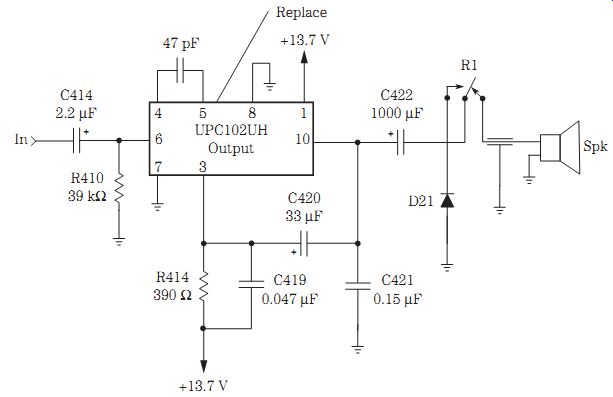
FIG. 8 A leaky audio output IC in an Xtal XCB-23A car radio caused the fuse
to open after replacement.
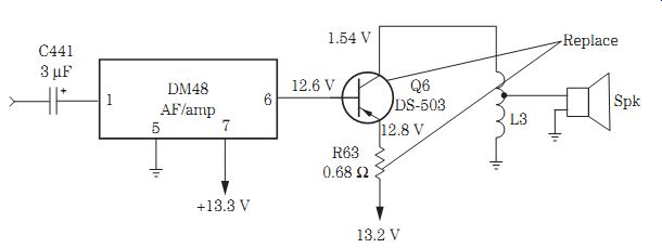
FIG. 9 Replace both the DS-503 power output and fusible resistor R63 for a
blown fuse and burned A lead.
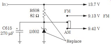
FIG. 10 Weak AM and FM reception in an Automatic 6500 early car radio was
caused by a leaky diode D302 and R608.
Common auto radio failures
Blown fuses and leaky transistors and ICs cause most of the problems within car radios. The most common failures are the audio output transistors and ICs. Worn or scratchy volume controls must be replaced after several years of wear and tear.
Distorted, intermittent, and weak reception often occurs in the audio circuits.
Fuse failure is caused by a leaky audio output component. Intermittent cassette audio also is caused by leads torn or worn off of the tape head connections.
Mechanical problems within the auto cassette player are speed, no-play, and eject problems. Speed problems result from worn or loose motor belts. Hold the capstan wheel, and if the motor stops rotating, the belt is good. Replace the drive belt when the motor pulley rotates inside the belt. A grinding noise can result from the capstan flywheel dragging against the bottom brace area. Install a new flywheel, or remove and tap the flywheel up into the correct position. Apply epoxy cement around the bottom of the capstan shaft and the body of the flywheel. Clean up the area with alcohol and a rag before applying the cement.
WEAK AM AND FM, AUTOMATIC 6500
Only a local AM station and a low rushing noise could be heard on an Automatic car radio. The tape player was normal. Critical voltage measurements were made on filter capacitors C615, C838, and C839. Hum was heard after touching a screwdriver blade to the center terminal of the volume control, indicating that the audio section was normal. The voltage check across electrolytic C615 was only 4.7 V that feeds to AM/FM selector switch SW904. Replacing the main filter capacitor C615, zener diode D302, and R608 solved the weak AM problem (Fig. 10).
WEAK AM RECEPTION
A defective antenna or bad receptacle, RF loading coil, RF coupling capacitor, and RF transistor and an extremely low supply voltage from the power supply can cause weak AM reception. In early car radios, the loading coil would shake loose, and the RF transistors produced most of the weak symptoms. Take a peek at the antenna receptacle and load coil for broken connections. Sometimes the RF coil has broken off and is found in the bottom of the car radio cabinet. Locate the RF coil, and trace out the circuit to the first RF or FET transistor. Take critical voltage tests on the RF transistor. An open or leaky RF transistor can cause weak AM reception.
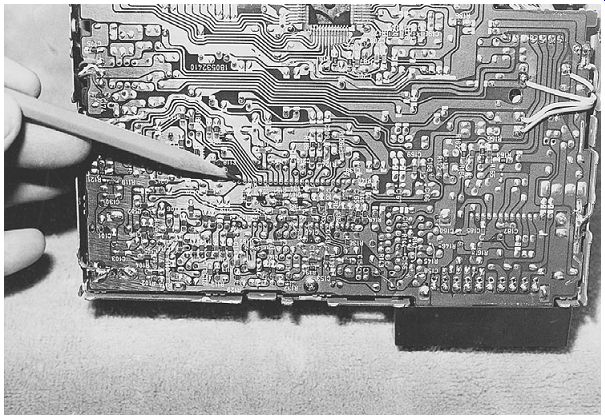
FIG. 11 Check for component markings on the PC board.
When the RF stage is not functioning, placing the positive probe on the collector terminal of the RF transistor may bring in a local broadcast station. This means that both the mixer and the oscillator circuits are normal. Check the voltages of the transistors or IC components in the mixer and oscillator circuits to determine if the circuits are functioning. You might find that both AM and FM operate from the same component.
Clean the AM/FM switch with cleaning spray.
The FM circuits consist of an oscillator and a mixer stage, as in the AM section, except at a much higher frequency (88 to 108 MHz). Most of the problems that occur in the FM stages are caused by leaky transistors, burned bias resistors, and improperly applied voltage. Check all three transistors within the FM circuits. Take critical voltage and resistance measurements.
If the AM section is normal, the FM problem must be in either the RF, oscillator, or mixer stages. Locate the FM RF transistor or IC from the antenna switch and small coils of wire. Notice that the FM coils are only a few turns of bare wire, whereas the AM coils have many turns on a form or rod. Parts in the front end can be located with markings on the PC board (Fig. 11).
A loud FM rush with the volume turned high can indicate a defective mixer or oscillator circuit. Sometimes a local station can be tuned in with a meter probe on the collector terminal of the RF FM transistor. Don't overlook a defective AM/FM switch.
WEAK CAR RADIO RECEPTION
Go directly to the antenna RF circuits when the signal is weak for either AM or FM reception. Locate the RF transistor tied to the coils and the AM/FM function switch.
Take critical voltage measurements. If a schematic is not available or you cannot find a transistor number, use the operating voltage, and find it in the manual of universal replacement transistors.
Determine if the transistor is an NPN or PNP type. If the radio is fairly new, you can assume that it is an NPN transistor. With a positive voltage measurement on the collector terminal and emitter tied to ground, the transistor is an NPN type.
Improper supply voltage to the AM or FM circuits can produce weak reception. If the supply voltage is low, visually trace the voltage back to the isolation resistors and zener diode circuit. Usually the voltage is regulated by a zener diode or transistor.
INTERMITTENT AM RECEPTION
Determine if the intermittent signal is in the front or rear end of the car radio. If the cassette or CD player operates, you can assume that the audio circuits are normal. Go directly to the AM circuits if the FM reception is normal, indicating that the IF section is okay. Try to determine if the AM signal is intermittent within the front-end section.
If the AM and FM reception are intermittent and the cassette player is normal, you know that the trouble must result from the function switch to the IF section common to both bands. Usually when the AM, FM, and cassette player are intermittent, the trouble lies in the audiofrequency (AF) to the speaker. When both AM and FM stages are intermittent, either the IF circuits or the supply voltage contains the defective component (Fig. 12). Don't overlook broken or poor outside antenna connections.
Poorly soldered boards, bad transistors or ICs, poorly soldered terminal leads or eyelet connections, poor antenna connections, a defective antenna jack, or intermittent voltage applied to the front-end circuits can cause intermittent problems. Suspect a dirty or worn volume control with intermittent reception.
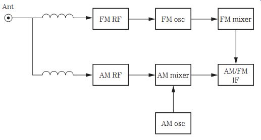
FIG. 12 Determine if the intermittent AM reception is within the AM circuits
when the FM, cassette, and CD player are working.
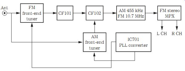
FIG. 13 Block diagram of the AM/FM IF circuits within present-day auto receivers.
New FM circuits
The old FM front-end circuits consisted of an FM RF amp, an FM mixer, and FM oscillator transistors, whereas the latest FM circuits contain an FM tuner unit. The FM tuner might consist of a large IC that provides the RF, mixer, and oscillator circuits in one component. A PLL controller controls the AM and FM tuning voltages for the front-end tuner. The PLL circuits use digital locked-loop circuits to synthesize AM and FM oscillator circuits. Instead of IF coils, ceramic filters are used throughout the IF and detector stages. Usually the AM 455-kHz IF stages are combined with the 10.7-MHz FM IF circuits (Fig. 13).
WEAK FM, AUDIOVOX BLM CAR RADIO
A defective FM mixer transistor may produce only a rushing noise and no stations tuned in, the open or leaky FM oscillator transistor may not tune in a station, and the defective RF FM transistor may tune in only a local FM station or none at all. Place a test probe from the meter to the collector terminal of the RF FM transistor, and try to tune in a local FM station. Suspect the early RF FM FET transistor with no or very weak FM station. TR101 in an Audiovox BLM-105031 car radio was replaced with a 2SK49 transistor or with a universal NTE-312 or SK3834 replacement. Most transistors within the auto radio can be replaced with universal transistors without any problems (Fig. 14).
SMD COMPONENTS
You will find both conventional and surface-mounted components within the latest auto cassette/CD player receivers. The surface-mounted devices (SMDs) can be mounted on one side of the board, with regular parts on the other. Several different components are found within the cassette/tuner board (Fig. 15). Notice the very fine PC wiring that connects the surface-mounted processor to the circuit.
Surface-mounted transistors and IC components are used throughout the circuits.
Besides surface-mounted ICs and transistors, diodes, capacitors, and resistors are used in many circuits. Notice that diodes can have two active tabs, and three-legged transistors can have different lead identifications. Power output ICs should be bolted to heavy heat sinks.
Digital transistors can be found in the audio preamp and the mechanism and system control. The digital transistor can have an internal resistor in the base circuit or an other bias resistor between the base and emitter terminals. When these digital resistors are checked with a transistor tester or the diode tester of the DMM, the resistance is higher in the base terminal. Likewise, the measurement from base to emitter with the internal base-to-emitter resistor is different. Compare another similar digital transistor with the low base-to-resistor test before discarding the suspected leaky transistor.
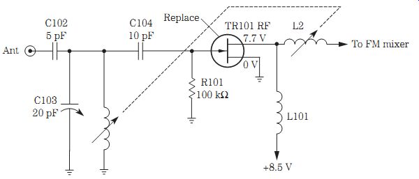
FIG. 14 Weak AM reception was caused by a defective TR101 RF transistor in
an Audiovox BLM-105031 car radio.
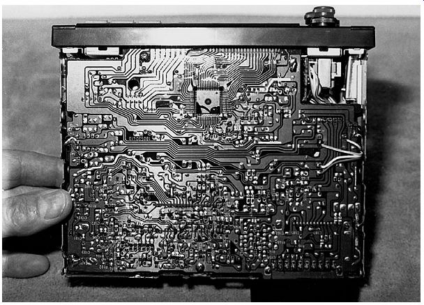
FIG. 15 SMD transistors, ICs, and processors can be found on the auto receiver
PC board.
Silent listening
In older car radios, the FM, AM, and cassette player are switched into the audio section with a manual switch. Today, you will find several diodes in each section that al low each section to be switched into the audio section. The AM and FM sections might be switched in with a separate AM/FM switch. The FM stereo and AM sections are switched in with diodes, and likewise, diodes are placed in the cassette player circuit when the power is applied to the cassette motor and audio circuits. No large manual function switch is found in the latest radios, cassette, or CD circuits.
Early car radio audio output circuits
Early car radios had power output tubes in the audio circuits that were replaced with a single audio output stage (see Fig. 9). The output transistor was replaced with a single or dual audio output IC. The dual audio IC might contain all or part of the audio circuits. Most of the audio stereo circuits are contained in one large IC (Fig. 16).
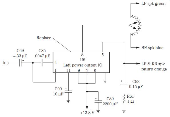
FIG. 16 A leaky U6 power output IC in a Delco 1980 series resulted in weak
and distorted music.
The FM multiplex (MPX) stereo sound circuits in a Delco 1980 series consisted of a driver IC U5 (DM116) capacitor coupled to a single power output IC in each stereo channel. The speaker fader control would shift the audio to the rear or front speakers.
Remember that most Delco auto radios do not have the speaker return wire at ground potential. You can damage the output IC if a permanent magnet (PM) speaker is connected to the output IC and chassis ground.
DEAD, NO AUDIO, REALISTIC 12-2103
No sound with no lights lit up was seen in a Radio Shack 12-2103 in-dash AM/FM stereo cassette player with auto reverse. Both a 0.5- and an 8-A fuse were blown in the 12-V and memory B+ line. Since both channels were dead, critical voltage tests were made on the power output IC701. The power IC showed signs of overheating and would blow the main fuse. IC701 was replaced with a TA8210AH replacement.
WEAK AUDIO
Just about any component in a car radio can cause weak sound in the audio circuits.
Try to isolate the weak section to the left or right channel. If both channels are weak, suspect an improper supply voltage on a common audio output IC. Weak audio can be caused by an open ground within the volume control. If sound is coming into the top and not at the center terminal, suspect a defective control.
Most weak audio conditions are caused by transistors, ICs, and coupling or bypass capacitors. If the left side is weak but not the right, isolate the weak stage with an external amp. Go from base to base on transistors or IC input and output terminals to determine where the signal is lost. Take critical voltage and resistance measurements when a suspected component is located.
DISTORTED LEFT CHANNEL
Any one or both channels can be distorted in an auto receiver. Most distortion problems are caused in the audio output circuits. Locate the power output transistor on the metal heat sink or metal chassis. Replace the leaky or shorted power output transistor or IC for a distorted left channel. Replace both leaky output transistors for a weak and distorted sound. A shorted decoupling capacitor in the power supply can cause dead or distorted audio. Check the suspected audio output transistors or ICs if they are running too warm to touch.
When the left channel is distorted and the right channel is normal, signal trace the left channel. Check for distortion at the volume control. Signal trace the rest of the audio circuit with an external amp to locate the distorted stage. Injection of a sine- or square-wave signal will indicate which stage is defective, with the scope as indicator.
Clipped sine waves or rounded square waves indicate distortion.
Improper voltage found on the transistor or IC can be caused by a leaky zener diode or transistor regulator. Don't overlook shorted or leaky bypass capacitors and leaky de coupling electrolytic capacitors for insufficient voltage that can produce distortion.
Overheated or red-hot output ICs definitely cause excessive distortion. Suspect the common output IC when both channels are distorted. Replace the leaky output IC (DM48) for left channel distortion in a Delco 1977 series car radio.
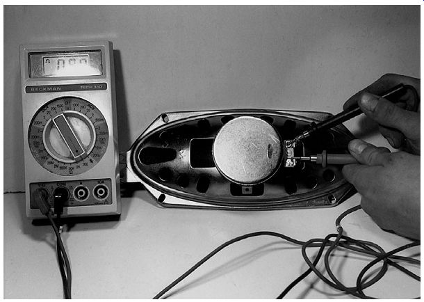
FIG. 17 Check the suspected open speaker voice coil with the low-ohm scale
of a DMM.
ONE OR BOTH CHANNELS ARE INTERMITTENT
Suspect a dual power output IC when both channels are intermittent. Sometimes a defective speaker coupling capacitor made by the same manufacturer can produce intermittent sound in all connected speakers. A shorted volume control can cause intermittent left and right channels. Broken foil or a broken coupling capacitor tied to the volume control can cause an intermittent channel. Weak and intermittent Ford D6TA-18806-AA car radio sound was caused by an intermittent AF amp module (N3).
When the radio warms up and then cuts out, suspect a leaky power IC. An excessively worn volume control can cause the audio to cut out. A shorted volume control also can produce intermittent sound. Broken coupling capacitor leads or an intermit tent break inside the IF coil can produce intermittent reception. Bad board connections, terminal leads, and speaker connections can cause intermittent audio.
Try to isolate the intermittent audio to the left or right channel. Locate the correct intermittent channel with an external amp connected to the volume control of the intermit tent speaker. Sometimes when signal tracing, if the probe is touched to a transistor terminal, the sound returns to normal. Here, a defective transistor has been shocked back to life; replace it. Carefully go from stage to stage to locate the intermittent sound problem.
Suspect the dual audio IC when both channels are intermittent. If the IC seems normal, check for a voltage change at the low-voltage power supply. Check for a broken voice coil wire in one speaker. Loose speaker wires and cables can cause intermittent sound problems. Check all speakers for intermittent open or loose clip connections (Fig. 17).
NOISY RECEPTION
Suspect an intermittent power output transistor or IC when a car radio operates for 10 minutes, pops, and goes dead. A loud popping noise in the speaker can result from a 500- uF filter capacitor that has broken loose from the PC board. Replace the audio output IC when the radio produces a cracking sound when it is first turned on. Suspect the AF transistor if there is noisy audio or the radio goes dead. You may have to replace both the driver and output transistors when there is a noisy left channel and an intermittent right channel. Replace the audio output transistor (Q6) when there is a pop and cracking noise in a Delco 01XPB4 car radio.
Check the output transistors and IC components for popping and crackling noises.
If you hear a loud pop and the channel goes dead, suspect the output IC. Sometimes when stations are tuned in or the radio is first turned on, a noisy output IC will cause a crackling noise. Low frying noises can be caused by noisy transistors or ICs.
A motor-boating noise found in either channel can be caused by the power output IC. Suspect the dual output IC when very loud motor boating is heard with the volume turned down. A chirping noise can be caused by open or blown speaker coupling capacitors. Check for poor grounds in the output circuits or on the IC heat sink when motor-boating and buzzing noises are heard. Suspect the first AF transistor for microphonic noise.
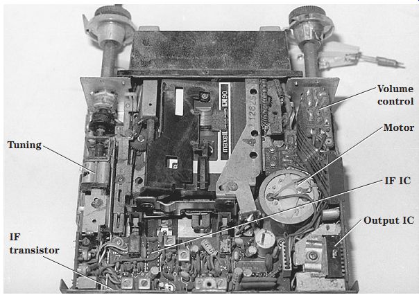
FIG. 18 Check the transistors, ICs, and various electronic components for
noisy car radio reception.
Check the large filter capacitors or output ICs when only a hum is heard in the speaker. Overheated transistors or IC output components can produce hum in the audio.
Low pickup hum can be caused by decoupling capacitors in the AF or driver circuits. Im proper grounds in the volume control or AF transistor circuits can cause a pickup hum.
Suspect a defective volume control for open or noisy conditions (Fig. 18).
Lower the volume control to determine if the noise or hum is in the audio or front end section. Suspect a red-hot output IC for a loud howling noise. Shunt the main filter capacitor for a loud or high-pitched noise. When a screeching noise is heard when stations are tuned in, check the small decoupling capacitors in the AF and driver circuits.
Inspect shields and look for loose IC mounting screws when a squawking noise is heard after the set warms up and with the volume turned down.
Auto radio hookup
The battery and ignition power sources usually are fused within an auto receiver.
When both a cassette and a CD player are found in a modern auto receiver, the two units are connected together with many cables and wires from each unit. You may find four different colored speaker wires from the unit with a red A lead in and a black ground wire. A simple car radio hookup might consist of only a left and right speaker cable, common ground for the speakers and radio returns, and a fused battery A lead that plugs into a socket at the rear of the auto radio (Fig. 19). Check Table 1, radio receiver troubleshooting.
High-powered amps
A 50- to 100-W amplifier might consist of a large high-powered IC or several transistors.
A 100- to 2000-W high-powered stereo amp may have 24 transistors within the input and driver stages with a total of 32 or more transistors in the amp and power supply.
Most high-powered amp power supplies have metal-oxide semiconductor field-effect transistors (MOSFETs) in the pulse width mode (PWM) and dc-dc converter circuits.
The root mean square (RMS) measures the power in watts that the amplifier can produce continually. A peak power rating is the maximum power that the amp can de liver during a brief moment of operation. RMS power at 2 ohms can tell you how much power the amp delivers into a 2-ohm speaker load (Fig. 20).
The high-powered amp within a radio, cassette player, or CD player may provide 15 to 50 W of peak power. You may find transistors and IC output components in these units. The really high-powered amp may use IC preamps, transistors, and many high powered transistors in directly coupled output circuits. For instance, an RF Punch 500A2 amplifier has an RMS power of 250 x 2 W with a bridged RMS power of 500 x 1 W in a single-output speaker.
In a typical high-powered auto system, you may find a separate amp for two tweeter speakers, another amp for midrange speakers, and a separate amp for four large subwoofer speakers. These high-powered amps and speakers normally are found in pickup trucks or large automobiles. The various 2- and 4-ohm speakers are connected to the two- and four-channel amps with left and right stereo channels.
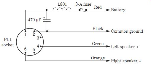
FIG. 19 A very simple car radio hookup that plugs into a rear socket.
Table 1. Radio receiver troubleshooting.
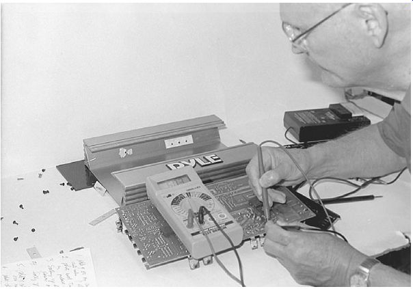
FIG. 20 Checking the power output transistor in a high-powered amplifier.
Dismantling high-powered amps
You will find a heavy-duty heat sink that is part of the amplifier's cabinet to dissipate heat from the MOSFET power supply and high-powered audio output transistors.
The molded heat sink is part of the outside cabinet or chassis. Remove the end pieces by removing several metal screws. Some of these covers have wires and sockets attached. Be very careful not to break loose cables and wires in removing the top metal cover.
Take a peek to see if the top cover will not come entirely loose until several power output transistors and MOSFET power supply transistor mounting screws are removed. Carefully pull up the transistors from their mounting insulators so that the chassis or cover can be removed. On some units the amp PC board will slide out of the bottom side of the metal chassis. After all repairs are made, make sure that the mica or clothlike insulators are replaced between the transistor and metal heat sink.
Locating the correct components
Look over the PC board for possible overheated or damaged parts. Overheated transistors may have gray or white marks on the body area with burned terminals. Check the body of each power IC for damage or chips blown out of the plastic body. Look for overheated and burned resistors that can be traced to leaky or shorted output transistors. High-powered output transistors are usually a little larger than regular TO-style transistors (Fig. 21).
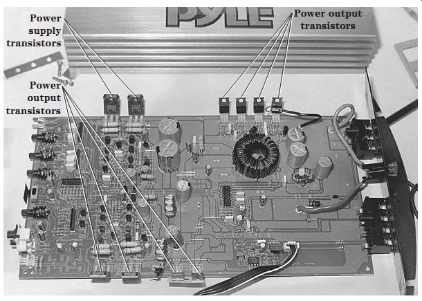
FIG. 21 Locate the various parts on the high-powered amp chassis before checking
the electronic components.
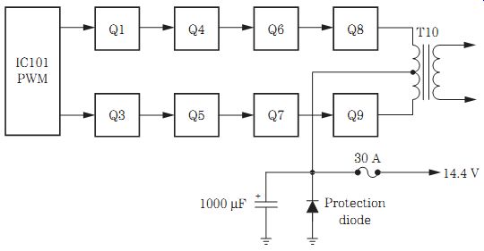
FIG. 22 A block diagram of the dc-dc power supply in a 170-W high-powered
amp.
Turn the PC board over and check for poor or burned traces and connections. Double-check the terminals of each power output transistor for burned or overheated connections on the PC board. You might find a poor connection on one of the high-powered transistors or MOSFETs in the power supply.
In a 50 x2 W amplifier with power output transistors, the power supply might consist of two regular transistors and two high-powered MOSFETs tied to a toroid trans former. The dc-dc input voltage of 14.4 V comes from the car's battery with an operating output of +25 and -25 V. Look for the largest filter capacitor on the PC board to locate the various power supply components. Notice if four fixed diodes are nearby. Check for the dc-dc output voltage across the 1000- uF 50-V electrolytics.
The pulse width mode (PWM) and the dc-dc converter power supply of a 170-W amplifier might consist of a PWM IC, a couple of input transistors, and six MOSFETs tied to a toroid transformer. The secondary winding ties to four fixed silicon diodes or a bridged-type rectifier component. The input voltage is around 14.4 V, with an output voltage from the power supply at 34.5 V dc. The +34.5 V feeds directly to the six MOSFETs (Fig. 22).
Transistor high-powered amps
A 2 x50 W auto amplifier might have four power output transistors in a directly coupled power output circuit. A negative -25 V and a positive +25 V are fed to the push-pull output transistors. Q16 might be a 2SA965 or a 2SB560 power driver transistor, whereas Q14 is a 2SC2235 or a 2SD438 PNP transistor. The final output transistor Q18 is a BD907 PNP, and Q20 is a BD908 NPN-type transistor. All high-powered output transistors should be replaced with the original part numbers (Fig. 23). If the originals are not available, try using universal re placement transistors.
In a 150- to 200-W amplifier, the output transistors operate at a higher 34.5 V and in a push-pull circuit. Both right and left stereo channel circuitry is the same, with two driver and two output transistors. Q206 and Q208 are driver transistors with NPN and PNP transistors, respectively. Q207 (NPN) and Q211 (PNP) are high-powered output transistors. There might be a total of 10 transistors in each high-powered output 150 to 200-W amplifier stereo channel (Fig. 24).
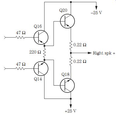
FIG. 23 The push-pull high-powered transistor output circuits in a 50 x 2
W amplifier.
FIG. 24 The right high-powered output transistor circuit in a 150- to 200-W amplifier.
IC high-powered amps
A 15- to 50-W amplifier might contain transistors or IC components. You may find a separate power IC in each stereo channel. In many of the latest low- or medium-powered output circuits, a dual IC might be found. Audio muting takes place at the input of the dual-power IC. Usually the power IC is found on a large metal heat sink.
In a 25-W Optimus 12-2103 AM/FM stereo cassette player with auto reverse, the left channel was weak and the right channel distorted. The audio signal was normal up to input terminals 2 and 7. Both outputs at pins 15 and 11 were weak and distorted on the external audio amp. IC701 was replaced with the original IC replacement (TA8210AH) (Fig. 25).
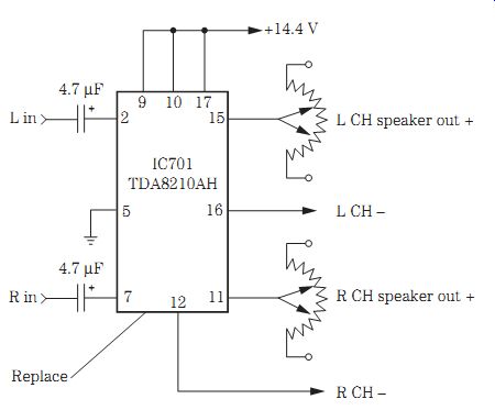
FIG. 25 Replace IC701 for weak and distorted channels in an Optimus 25-W power
output amplifier.
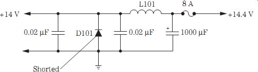
FIG. 26 The repeated failure of the 8-A fuse can be caused by a defective
protection diode (D101).
Troubleshooting high-powered power supplies
A simple power supply circuit is found in amplifiers under 50 W and might consist of the A lead, hash choke L101, a 5- to 10-A fuse, and several bypass capacitors. Some car radio power supplies have a polarity diode (D101) that protects the radio circuits if the battery is charged up backward or installed backward. D101 will blow the 8-A fuse if +14.4 V is applied to the A lead (Fig. 26).
You might find a transistor voltage regulator circuit, diode protection, and decoupling electrolytics in a low-voltage power supply. A bad electrolytic (1000 uF) on the voltage in put line can cause some hum and motor-boating problems. An open decoupling capacitor (500 to 1000 uF) can produce motor boating and a chirping noise. A broken loose filter capacitor from the PC board can cause a loud popping noise. A dead Delco 51CFP1 car radio only hums with a leaky decoupling capacitor in the power supply.
Check for a shorted or leaky transistor in the high-powered power supply that can damage driver transistors and MOSFETs. A leaky or shorted MOSFET can cause one or two other transistors to be damaged because they are connected in a series-parallel power supply circuit. Quickly check all transistors with a semiconductor tester or the diode tester of the DMM. Likewise, check all diodes in the power supply with the diode tester of the DMM. Remove one end of the fixed diode for accurate measurements.
Discharge all electrolytics within the power supply before taking leakage or ESR tests. You can damage the ESR meter if electrolytics are not discharged.
Check each electrolytic for shorted or leaky conditions with the 2-kilohm scale of the DMM.
Do not overlook a shorted silicon diode or bridged diodes in the secondary winding of the dc-dc power supply. Leaky or dried up electrolytics within the power supply can load down the dc-dc circuits and cause the high-voltage power supply to not function.
Sometimes a shorted or leaky transistor in the amplifier can shut down the power sup ply and lower the dc output voltage. Check overloaded and shut-down transistors for leaky or shorted conditions.
If the 20- to 30-A fuse keeps blowing, suspect a shorted MOSFET, diodes, or electrolytic capacitors in the dc-dc power supply. Remember, if the polarity diode becomes shorted, the main fuse will keep blowing until the diode is replaced. Check for the right amp replacement fuse, silicon diodes, shorted filter capacitors, and MOSFETs when the fuse keeps blowing in the dc-dc power supply (Fig. 27).
Servicing high-powered amps
Check for a blown fuse if the high-powered amplifier is dead. Take critical voltage tests across the largest filter capacitors. Service the high-powered power supply if there is no or low voltage to the output transistors. Make sure that the dc-dc power supply is functioning before tackling the high-power output circuits. Make sure that a speaker load resistor (7.5 ohm, 10 W) is shunted across each stereo speaker channel. The dead channel might be caused by an open regulator transistor in the power supply.
The high-powered amp might have a dead right channel, weak left channel, distorted and weak audio, intermittent sound, a noisy channel, or hum in the speakers.
The dead channel might be caused by a defective transistor or IC component. Quickly check all transistors with the diode tester of the DMM.
Remember that when one transistor is found open or leaky, look for another one or two damaged in the directly coupled audio output circuits. Take critical voltage measurements on each transistor, and compare with the same voltage in the normal stereo channel. Do not overlook a dead speaker caused by an open or blown speaker fuse or a defective speaker relay circuit.
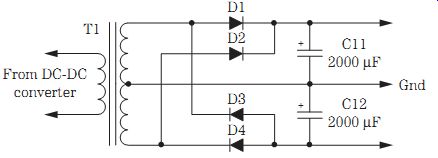
FIG. 27 A shorted diode or leaky filter capacitor can shut down the dc-dc
power supply.
A weak or distorted channel can be checked with an external audio amplifier. Always use an isolation transformer with the external audio amp to prevent damage to the test equipment or components within the amplifier. Extreme distortion symptoms generally are located within the high-powered output circuits or head unit. Leaky transistors, diodes, ICs, and coupling capacitors and bad bias resistors cause most distortion symptoms. The weak stage can result from leaky or open input and driver transistors and ICs, bad coupling capacitors, and a change in resistors. Compare the weak or distorted stage at the same point in the normal stereo channel. A shorted or leaky power output transistor can damage the emitter resistors.
When the audio signal is slightly weak or distorted, use the signal generator or external audio amp to locate the defective stage. Clip a 1-kHz audio signal from the generator to the inputs of the amp, and connect the external amp to check out each stage for the same amount of audio. Go from base to base of each transistor and notice the same volume setting in both channels. As you proceed through the amplifier circuits, the signal will get weaker in the external audio amp. Critical voltage and resistance measurements with transistor tests can locate most high-powered amplifier problems.
Bridged amp outputs
A high-powered amplifier might produce 700 to 2000 W bridged into a 4-ohm load. The two-channel high-powered amp can be bridged by connecting the positive terminal of the left channel to the positive terminal of the high-wattage speaker. The negative terminal of the right channel is connected to the negative terminal of a single speaker. A 2 x 85 W amp at 4 ohms with a maximum output of 2 x 350 W at 2 ohms can be bridged in a mono speaker at 1 x 700 W. The single-bridged speaker should be able to handle at least 700 to 1000 W of power (Fig. 28).
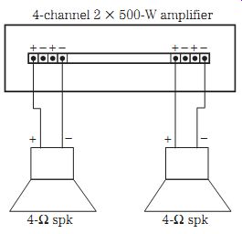
FIG. 28 A bridged speaker hookup tied into a 2 x 500 W four-channel amp with
a 4-ohm speaker load.
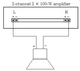
FIG. 29 A mono speaker is connected to the left + channel and the negative
terminal - to the right channel in a bridged speaker hookup.
Two-channel amp hookup
A two-channel amp has a left and right channel in a stereo amplifier, whereas a four channel amp has four separate speakers for each channel. Connect the positive lead of the left output to the positive terminal of the speaker. Likewise, connect the negative output of the left channel to the negative terminal on the speaker. One speaker is connected to the left side and another speaker to the right side (Fig. 29). Match the polarity of the speakers with the polarity of the amplifier for greater power and frequency response.
The two-channel amp can be bridged for a mono (1) PM speaker for higher wattage. For example, a 2 x 100 W two-channel amp can be bridged at the output terminals for a speaker output of 200 W. Just connect the positive terminal of the left channel to the positive terminal of the speaker and the negative terminal of the right channel to the negative terminal of the PM speaker.
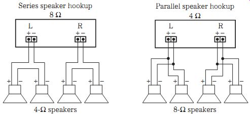
FIG. 30 The 4-ohm speakers are connected in series to match an 8-ohm two channel
amplifier.
Matching impedance
The impedance of the speaker should match the output impedance of the high powered amplifier. A 4-ohm speaker should be connected to a 4-ohm amplifier and not to a 2-ohm impedance. Poor impedance matching can result in poor fidelity and power or volume. The speaker voice coils can be wired in series, just so the impedance of both units matches. For example, two 4-ohm speakers can be wired in series to match an 8-ohm impedance of the amplifier. When speakers are wired in parallel, the impedance is cut in half (Fig. 30). The early voice coil impedance was around 3.2 ohms, and the latest high-powered speakers impedance is 4, 8, and 16 ohms.
High-powered speaker hookup
Several different size speakers might be found in a high-powered amplifier system. A 500-W amp may feed a high-pass crossover network to a tweeter and midrange speaker in each channel. The same amp might have a low-pass level to a very large subwoofer speaker (Fig. 31).
Some head units are fed to a control equalizer unit, and this signal is fed to a separate 500 x 2 W amplifier. In turn, two large 10-in speakers are wired to the 500-W amplifier. The same control equalizer unit also might feed to a 75 x 2 W amplifier and in turn feeds a two-channel crossover network that feeds a tweeter and midrange speaker in each left and right stereo channel.
High-powered amplifiers can be built into a pickup truck as well as in an automobile. The deluxe speaker hookup might have a VCR, DVD, and screen monitor inside the pickup. The signal is sent to a 500-W amplifier that powers two different crossover units. The low-pass network is connected to two 15-in subwoofer speakers. The high and midrange power is fed to a tweeter and midrange speaker in the left and right output channels (Fig. 32).
The tweeter speakers, such as a really small PM speaker or a horn-type speaker, might be connected to the high-pass frequency network. The midrange speaker might have a 5- to 8-in speaker. A subwoofer can be a 10- to 18-in PM speaker for the bass frequency response of 20 to 500 kHz, whereas an 18-in speaker response is from 20 to 150 kHz.
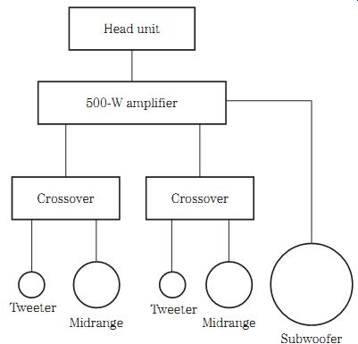
FIG. 31 A 500-W high-powered amplifier tied to crossovers and the various
speakers.
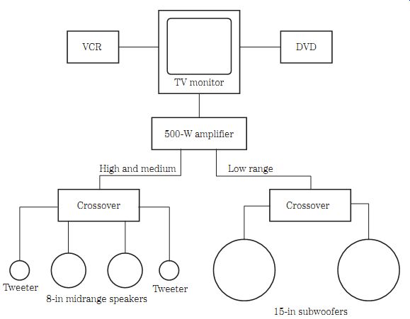
FIG. 32 A front-end high-powered amp, VCR, DVD, and TV monitor with the various
size speakers in a pickup truck.
Auto radio speakers
The speakers found in early car radios were 4, 5, 7, 8, or 6x9 in with a 3- to 4-ohm impedance. Along came the hybrid radio with 4 x 6-, 4 x 9-, 4 x 10-, 5-, 6-, 6x 9-, or 7 in PM speakers. The all-transistor car radio might have 4 x 6-, 4 x 10-, 5 x 7-, 5-, 6-, 6 x 9-, 6 x10-, or 7-in speakers. The deluxe auto receiver might have a 4 x 10-, 5 x 7-, 6 x 9-, or 6 x 10-in speaker with a 4-, 6-, 8-, 16-, or 40-ohm voice coil.
The cones of early car radio speakers were constructed of paper and very light material. A high-powered subwoofer speaker has high temperature and composite cones, poly, polypropylene, poly and graphite linear cones that can create realistic sound. You might find a stiff Kelvar paper cone in subwoofer speakers. A surround speaker may use a silver-injected poly cone with a thermal paper and fiber-poly type of surround, and on it goes.
The voice coil is found on one end of the cone that moves through a magnetic field with a PM magnet. The early car radio replacement has an impedance of 3, 4, 8, 10, or 16 ohms. The voice coil impedance of a high-powered speaker is usually 2 or 4 ohms.
Some auto speakers are found in very odd shapes and must be replaced with the original or they will not fit into the required space. Simply go to the car dealer and pick up a speaker that will fit in the same model of automobile.
The factory car rear-deck speaker openings might take a 4 x 6-, 5 x 7-, or 6 x 9- in speaker. Speakers mounted within the front deck or dash might be a 4 1/2-, 5 1/4-, 4 x6-, or 4x10-in PM speakers. The different size speakers found in the rear wheel mount might be from 5-, 5 1/4-, 6 1/2-, 6 x 8-, or 6 x 9-in speaker openings. In high-powered amps, the very large speakers (12, 15, 18 in) might be mounted in columns or specially constructed baffles and mounted in the back or in the trunk area.
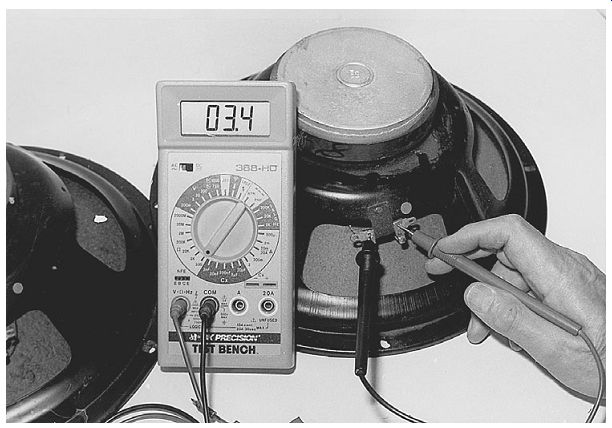
FIG. 33 A 15-in 4-ohm speaker tests only 3.4 ohms on the DMM.
Speaker problems Since an automobile operates in any kind of weather, auto speaker cones have a tendency to warp and drag. The defective speaker might have an open voice coil, bad voice coil connections, and drag against the metal pole piece. By pushing up and down on the speaker cone with the radio operating, you can locate an intermittent sound with a bad voice coil winding or poor connection. A mushy speaker cone drags against the center magnet pole piece. A dead speaker may have an open voice coil or a broken speaker connection.
Check for an open voice coil with the low-ohm range of the DMM. A volt-ohm-milliammeter (VOM) measurement of the voice coil will be greater than the speaker impedance. A DMM low-ohm test will show that the speaker impedance can be from 0.5 to 1 ohm less than the actual impedance. A 15-in high-powered speaker has an impedance of 4 ohms and a 3.4-ohm resistance measurement on the DMM (Fig. 33). Always have a speaker connected to the amplifier channels or a low-ohm resistor when servicing a high-powered amp. The large PM speaker can be damaged by applying too much volume or boom power from the amplifier.
Most speakers can be replaced from just about any electronic parts or mail-order dealer. The different sized auto speakers can be picked up at the auto dealerships. Very large midrange, woofer, and subwoofer speakers can be obtained from electronics part or mail-order dealers and Radio Shack. Do not overlook the electronics mail-order firms for speaker replacements and enclosures. Make sure that the speaker size, voice coil impedance, and weight of the magnet are the same as the speaker being replaced.