After World War II, the radio phonograph was included in the console radio, and now the CD player has taken its place. At first the CD player was found in a portable unit; then it progressed to the boom-box cassette player and advanced to the auto radio/cassette/CD player and to the CD changer, and now the CD player is located in the TV CD and DVD player. A portable and boom-box CD player may operate off batteries or the power line (Fig. 1).
Of course, a CD player in an automobile operates from the car battery, whereas a home system may include an AM/FM/MPX receiver with cassette and CD players.
A CD changer may be found in a tabletop home system or in the trunk of an auto mobile. Today, a CD player may be found even in 13-, 19-, and 27-inch TV/VCR combo players.
Like a videocassette recorder, a CD player is difficult to service without a schematic, so try to locate a diagram to service such a player. However, there are many tests that can be done without a schematic. A block diagram will help in isolating the various circuits. The block diagram of each circuit may help you to understand how CD circuits perform.
Critical waveform, voltage, and audio tests may locate the defective circuit.
Checking the laser diode, radiofrequency (RF), and encoding frequency modulation (EFM) signals will indicate if the laser pickup assembly is functioning. voltage measurements and signal waveforms on the loading, slide, and disc motors can determine if the motor circuits are normal.
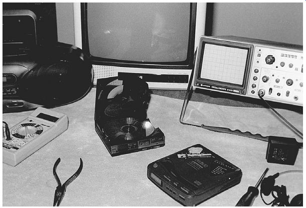
FIG. 1 CD players can be found in portable, home, auto, and tag-along devices
and inside a CD changer.
Laser diode circuits
The laser optical assembly is one of the most important sections of a CD player. If the laser diode or optical circuits cannot be repaired, the unit may be thrown out because the cost of replacing the optical assembly is rather expensive. Often the cost of replacing the whole optical assembly is too expensive. Of course, some components within the optical assembly can be replaced, if they are available.
Make sure the RF signal from the pickup assembly is functioning before other re pairs are made.
The laser circuit consists of photodetector diodes (A, B, C, and D), objective lens, focus and tracking coils, collimator lens, beam splitter, monitor, and a laser diode in some CD players. The tracking diodes are E and F, whereas the monitor diode is MD and the laser diode is listed as LD. The photodetector diodes sense the EFM signal from the disc. The tracking detector diodes (E and F) control the tracking, and the focus diode keeps the beam on the disc. The EFM signal from the photodetector diodes is applied to the RF amplifier circuits (Fig. 2).
The 8- to 14-bit (EFM) signal is a very complex encoding scheme used to transfer digital data to a form that can be placed on a disc. The EFM waveform is found at the output of the RF integrated circuit (IC) or transistors and is fed to the digital processor. When the error signal is not present at the servo IC, the chassis might shut down at once.
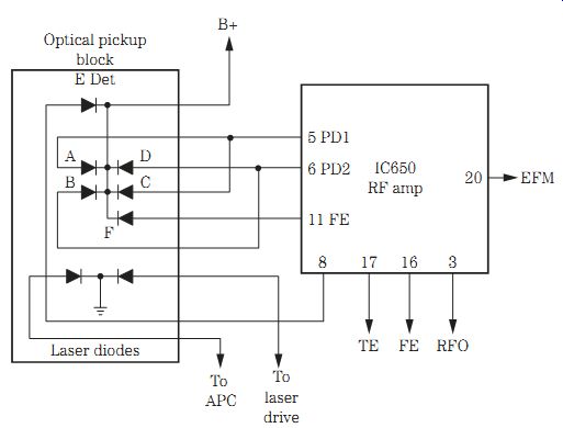
FIG. 2 The laser circuits consist of photodetector diodes (A, B, C, and D),
a monitor, and a laser diode.
The laser diode output can be checked with a laser light meter or infrared indicator. Measure the dc source applied to the laser diode. This might be a direct voltage or voltage applied from a laser driver transistor or IC. The laser diode output is fed directly to the RF amplifier IC or processor.
DIAMONDS ARE EXPENSIVE
The RF or eye pattern represents a diamond-shaped pattern taken from the output of the RF amplifier stage. When the eye pattern is not found at the RF amplifier IC or transistors, the CD player will shut down automatically. The laser optical assembly must be operating with a normal RF amplifier and an adequate low-voltage source feeding the front-end circuits. Scope the eye pattern (EFM) at the RF amplifier output (Fig. 3). This RF signal feeds the digital signal processor IC and servo circuits.
DO NOT LOOK AT ME
Do not look directly at the laser beam or lens at any time. The laser optical beam can not be seen by the naked eye. Service technicians should avoid looking directly at the laser beam (Fig. 4). Keep a CD loaded on the disc platform all the time. Keep your eyes at least 25 in from the optical laser beam. Place a conductive mat under the test equipment and player while servicing it. Wear a wrist strap to leak off body charges to the chassis and ground. Do not forget to remove shorting or interlock devices after repairing the CD player. Take critical leakage tests. Replace the critical parts with originals.
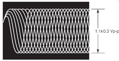
FIG. 3 Check the eye pattern when the CD player is inoperative.
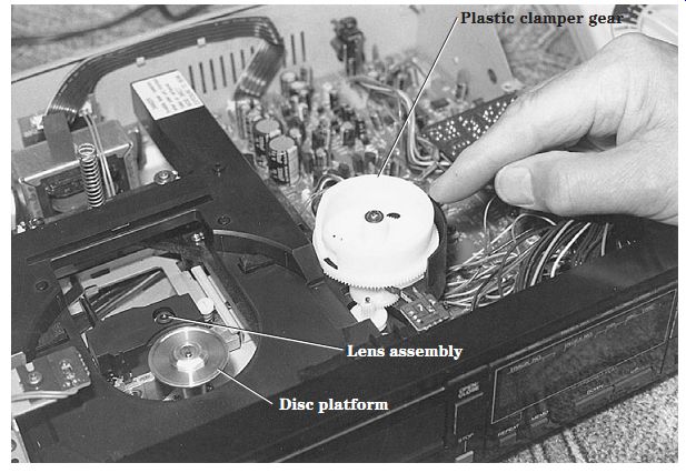
FIG. 4 Keep your eyes away from looking directly at the lighted lens assembly.
RF AMP PROBLEMS
The RF amplifier receives the weak signal from the photodetector diodes and amplifies the digital signal as an RF pattern. Suspect a defective optical assembly when the RF signal is weak or missing. Measure the voltage applied to the photodetector diodes. Look for a test point on the printed circuit (PC) board for a quick scope test of the RF amplifier IC. An early RF amp might consist of several transistors, whereas the latest CD players contain IC components. The RF amp sends an EFM signal to the digital signal processor and a mirror signal to the servo mechanism.
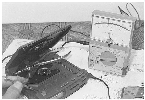
FIG. 5 Check the laser diode lens assembly with a laser power meter.
Determine if the laser diode is emitting light with a laser power meter or infrared indicator strip. Place the power meter probe across the laser lens assembly. Do not look directly at the laser light. Move the probe back and forth to get the maximum reading on the meter. If the meter hand hits the peg, change the meter setting to the next highest measurement (Fig. 5). When the laser diode appears normal, place a disc on the disc mount and take an RF (EFM) scope waveform at the RF amp output.
Clean cigar or cigarette smoke residue and dust from the lens assembly. A dirty lens assembly can cause the disc to spin slowly and sometimes not play. Clean the lens with Windex. Wipe the lens assembly gently so as not to throw it out of line or bend the sup porting spring. A dirty lens assembly can make a disc start and stop. Replace the laser scanner assembly when the CD rotates intermittently. A bad optical pickup assembly can cause static in the audio when the disc is playing. Usually the CD player will shut down at once with no EFM eye pattern.
Suspect a defective RF amp transistor or IC when no EFM pattern is found at the output terminal. Measure the supply voltage at the RF amp circuits. Improper or no voltage at the RF amp transistor or IC can result in no scope waveform. Test the RF transistor with a semiconductor tester or the diode tester of the DMM. Always be careful when working around the optical pickup assembly.
DIGITAL SIGNAL PROCESSOR
The signal processor IC usually contains the clock generator, EFM, data, LUCH, mute data, digital filter, timing control, oscillator, modulation, constant linear velocity (CLV) servo, and servo system control. The RF output signal is fed to the input of the digital signal processor and the output to a digital-to-analog (D/A) converter circuit.
The EFM comparator changes the RF signal into a binary value. The binary-coded signal is then fed to pin 5 of the digital signal processor (IC3), where it is demodulated, a bit clock is generated, errors are detected and corrected, lost data are interpolated, and the subcode for track number/elapsed time is demodulated. A bit clock must be derived from the EFM signal by a variable crystal oscillator (VCO) so that the data in the EFM signal can be read.

FIG. 6 Block diagram of a portable CD player.
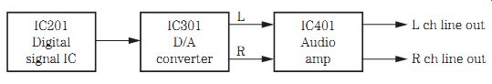
FIG. 7 The digital-to-analog (D/A) converter circuit provides audio in the
left and right channels.
The demodulated EFM signal is converted to digital data and stored in a random access memory (RAM) (IC3). The data are read from the RAM and fed to the digital filter and then to a D/A converter (IC11) (Fig. 6).
A defective digital signal processor IC can cause a high-pitched noise in the audio while a CD is playing. A defective RAM IC can cause noise in the sound. Replace the RAM IC with a ticking noise while the CD is playing. A bad RAM IC can cause distorted sound in the speaker. Replace the RAM IC with a low-level noise in the audio. Check the crystal in the digital processor circuits when there is noise in the sound and no clock signal.
Digital-to-analog (D/A) converter
The D/A converter receives a digital signal from a digital filter network or from the signal processor stage. The D/A converter (IC301) converts a digital signal to an analog signal (Fig. 7). The audio signal is then fed to the final output amplifier. One or two stages of amplification are found in most CD players. This audio signal is fed to a stereo line output jack or to a separate headphone amp. The line output voltage of most CD players is around 2 V.
Replace the D/A converter IC when there is no sound in the left channel. Check both the right and left output channels from the D/A converter for no sound in either channel. Replace a bad or noisy D/A converter IC when there is background noise during the quiet spaces of music. Distorted audio can result from a defective D/A converter IC. The D/A converter (IC203) in a Sharp DX100 CD player caused extreme distortion in both audio channels. No audio in the left channel of a Aiwa DXM77 CD player was caused by a low-pass filter (LPF101).
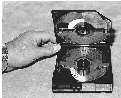
FIG. 8 The top lid must be closed before a portable CD player will operate.
CD power supplies
A portable CD player may operate from a 3-V dc battery source or from an external power line cord adaptor. A power and change switch from the positive terminal of the battery is applied to the regulated supply as well as to the door switch. The door or cover of a portable CD player must be closed before the 3-V source is applied to the lens assembly. This protects the operator's eyes from looking down on the lens assembly (Fig. 8).
In a boom-box cassette/CD player, the low-voltage power circuits are quite simple, with bridge rectification and high filter input. The cassette motor and other circuits have a transistor-regulated voltage source, whereas the CD circuit has one or more transistor-zener diode regulators. A large input filter capacitor (2200 to 3300 uF) provides voltage to a CD regulator circuit. The output voltage may have a motor regulator transistor circuit that regulates the voltage to the cassette player and motor. The CD circuits may have several transistor-diode or IC regulators.
When higher dc voltage is needed within auto or home CD player systems, a dc-dc converter circuit provides a 5- to 10-V regulated source. Of course, an auto CD player operates from the car battery, whereas a home theater is plugged into an ac power line.
You will find several transistors and zener-regulated circuits within the higher-voltage sources. Check the power supply voltage at the largest electrolytic filter capacitors.
Most power supply problems are related to leaky or dried-up filter capacitors, open fuses, and bad decoupling capacitors and transistor regulator circuits. A shorted or leaky filter capacitor can blow the fuse and damage the small power transformer if the unit is not fused. Dried-up filter capacitors will cause hum in the sound at all times. Suspect a defective filter capacitor when hum is heard in the speakers with the volume turned down.
Leaky or shorted decoupling electrolytics can cause hum and low voltage to other circuits within a CD player. Simply clip in a known electrolytic across the suspected filter capacitor with the CD player turned off. If the hum disappears, replace the defective filter capacitor. Check all filter capacitors for no power to the CD circuits.
Do not overlook a defective regulator transistor or IC. Check the voltage in and out of the transistor or IC. An open transistor or IC regulator will have low or no dc output voltage. A leaky regulator transistor can cause a low- or high-voltage output depending on what elements in the transistor are leaky (Fig. 9). Besides voltage transistor regulators in the power supply, the servo and motor circuits also have transistor regulators.
Intermittent sound and clicking of the protection relay were caused by poorly soldered contacts on the regulator transistors.
No audio and a dim liquid crystal display (LCD) in a Pioneer SXV500 CD player were caused by a change in resistance of R328 (8.2 kilohms), which supplies a 15-V regulator transistor Q312.
Suspect a shorted filter capacitor or leaky silicon diodes when no ac voltage is found at the power transformer (Fig. 10). Measure the ac voltage across the secondary winding of the power transformer. Pull the ac cord if no voltage is found across the secondary winding. Often, when a component in the input of a power transformer becomes shorted and the primary winding is not fused, the primary winding goes open because it has so many turns of a very fine wire. Quickly take a 2-kilohm ohmmeter continuity measurement of the primary ac winding (Fig. 11). No low-ohm measurement indicates that the transformer primary winding is open; replace the transformer.
Replace the R305 and R306 (430-ohm) resistors in the regulator voltage circuit feeding the preamp ICs that caused one distorted channel and the other channel okay in a Pioneer SX780 CD player.
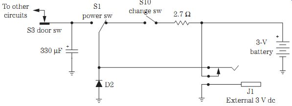
FIG. 9 A portable CD player can be operated by batteries or an ac power line
adaptor.
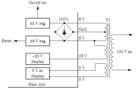
FIG. 10 A defective 5-V regulator prevented operation of a Denon DCM 560 CD
player.
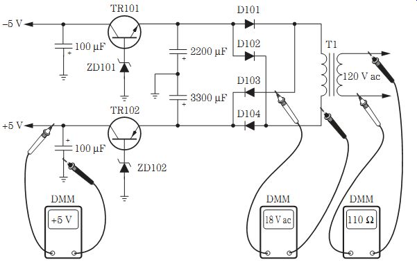
FIG. 11 Check the primary winding for open conditions with the 2-kilohm ohmmeter
scale and the ac voltage at the secondary winding of the transformer.
Check those electrolytics with an ESR meter
When hum is heard in the sound, check those electrolytics with an equivalent series resistance (ESR) meter. Discharge all terminals of the electrolytic by shorting them together. Make sure that no voltage is found on any capacitor terminals before making ESR tests. A charged voltage can destroy an ESR meter. Check across the capacitor's terminals with the ESR meter probes, and read the condition of the capacitor on the meter (Fig. 12).
A normal electrolytic will test in the green area of the meter. If the capacitor registers in the yellow or red area, replace it. A dried-up electrolytic will show up in the red or yellow area. Check the electrolytic for leakage or shorted conditions by taking a 2 kilohm measurement across each terminal to common ground.
Check all electrolytics within the power supply in the same manner. Do not over look a decoupling electrolytic for a loss of capacity. The extremely low capacity of small electrolytics (1 to 10 uF) results in a tendency to lose even more capacity. Check all electrolytics at the various voltage sources within the power supply. A weak or low dc voltage source can be caused by a defective electrolytic at that voltage source (Fig. 6 13). A Sony CDXA20 CD player was dead with no power, and this was caused by a leaky 330- uF, 6.3-V electrolytic.

FIG. 12 Check all electrolytics in the power supply with an ESR meter.

FIG. 13 Various components can cause failure in a low-voltage power supply.
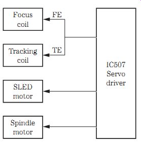
FIG. 14 The focus and tracking coils may be driven by one large servo driver
IC507.
Focus amp problems
The focus coil keeps the lens assembly focused at all times and is driven by a focus driver transistor or IC. The focus driver receives the focus commands from a servo IC, whereas the servo IC is driven by a signal from the RF amp and signal processor.
In some CD players, you may find that one servo driver IC controls the focus and tracking coils and the SLED and spindle motors. The focus and tracking coils are located within the optical pickup assembly (Fig. 14).
Take a peek at the focus and tracking coils when the CD player is first turned on. Both coil assemblies will move and search, indicating that the circuits and coils are normal.
Take a waveform test across the focus coil when the CD player is turned on. Check the supply at the driver transistor or IC. Measure the voltage across the focus coil winding.
Turn the set off and take a continuity ohmmeter test of each coil for an open coil winding.
Battery focus coil check
The focus and tracking coils can be checked by applying a low dc voltage across the coil windings. Remove the ground lead from the focus coil, and insert the battery voltage. Notice if the focus coil moves when 1.5 to 3V is applied across the coil. Now reverse the battery polarity and notice if the coil moves in another direction. Test each focus and tracking coil in the same manner. You can assume that both coils are normal if they move when a battery source is applied to them.
Tracking amp problems
The tracking circuits are designed to keep the optical lens assembly on the right track as the CD spins. Usually, the tracking coil is operated by the same driver and servo IC. Take a low-ohm continuity measurement across the tracking coil to deter mine if it is open or has a poorly soldered connection. A tracking coil waveform across the tracking coil indicates that the tracking coil and driver IC or transistor are normal. Locate the tracking coil assembly wires, and trace them back to the driver transistor or IC. Take a supply voltage measurement on the driver IC when the tracking coil is not moving (Fig. 15).
Besides a defective tracking coil or driver component, a laser head groove gear may be split, causing improper tracking. A bad ribbon cable to the laser head assembly from the main PC board can cause the player not to play the outer track on the CD. Mistracking and skipping can be caused by a bad worm gear. In an Onkyo DX530 model, improper tracking was caused by a split gear at the laser head assembly.

FIG. 15 The tracking coil may have a resistance of 4 to 10 ohms, whereas the
focus coil has a resistance of 20 to 30 ohms.
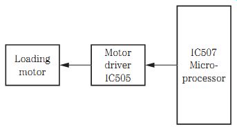
FIG. 16 The loading motor is driven by driver IC505 from a microprocessor
IC507.
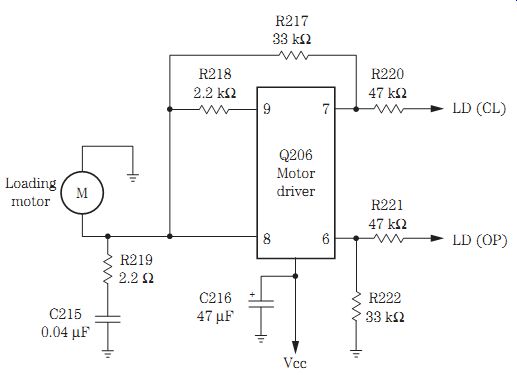
FIG. 17 When the loading motor was tapped on the end with the screwdriver
handle, the motor started to rotate in an Onkyo DX-C606 CD player.
Loading motor problems
The loading motor moves the tray outward and loads the CD into the CD player. In a home entertainment CD player, the loading motor moves the tray out, the CD is loaded, and the tray motor pulls the tray back into the CD player. In most cases the loading motor is driven by a motor driver transistor or IC from a microprocessor or control system IC (in the auto CD player). The CD is set on the motor drive spindle after opening the door (Fig. 16).
Intermittent operation of the loading tray may result from foreign material within the track area, a slipping drive belt, or a jammed mechanism. A dirty open/close switch can cause intermittent operation. Check the tray switch by shorting across its terminals. Notice if the tray rack or gears are binding. When the loading motor drives a belt to load and unload, check the belt for oil spots. Check the drive belt for worn or cracked areas. Inspect the loading pulley or plastic gear assembly for stripped or broken teeth.
Check the CD changer loading tray for wires caught on the bottom of the moving tray.
When measuring the voltage applied to the motor, you might find 14 V to open the tray and 24 V to close the tray and pull the CD into the player (Fig. 17).
A defective loading motor will not load the CD. Check for a broken or loose motor drive belt. Check all the photo interrupters and replace when the CD will not load. The tray would not move back and forth in a Magnavox MX3702 CD player with a leaky C04 (470- uF, 10-V) electrolytic capacitor. Take a critical supply voltage (Vcc) measurement on the loading motor driver IC.
Disc and SLED motors
The SLED and slide motors move the optical pickup assembly on rails from the in side to the outside of the CD, whereas the disc motor rotates the plastic CD. The disc motor might be called a spindle motor, whereas the SLED or feed motor sometimes is called a carriage motor. Both these motors are controlled by a system control or servo driver IC. The disc motor starts out in the center of the CD at approximately 500 rpm and moves toward the outer rim at 200 rpm (Fig. 18).
The slide or SLED motor brings the laser pickup within the fine tracking control range. A tracking servo signal is used to move the pickup horizontally. The tracking coil keeps the pickup assembly on the track.
Check the spindle disc motor and slide motor with voltage and continuity measurements as you would the rest of the motors in a CD player. Check the spindle motor transistors or IC if the motor tests normal. Measure the voltage applied to each motor.
Most of these motors operate from a 5-, 8-, or 10-V source at the driver transistor or IC.
Clean the lens assembly with Windex when the disc motor spins slowly or will not move. Intermittent playing of the CD or slow spinning of the CD results from a dirty lens assembly. Check for open resistors in the carriage or slide motor circuits when the player plays only part of the CD. Replace the spin motor when the CD will not rotate, skips, or stops. Check the table height when replacing the disc motor.
FIG. 18 The CD sits directly on the spindle of the disc or spindle motor.
In a Pioneer PD-7010 model, the carriage or slide motor would not rotate. Very low voltage was found on the slide motor terminals. Both the 10-V sources feeding the driver IC3 were quite low, indicating a defective 110- or 210-V source or a leaky IC3. When the voltage source was removed from pins 5 and 10, the voltage re turned to normal. Driver IC3 was replaced, and this restored slide motor operation (Fig. 19).
Intermittent skipping
Clean the lens assembly when there is intermittent skipping of a CD. A defective laser scanner assembly can cause intermittent CD operation. Check for a leaky IC in the 5-V source when the CD stops in the middle of a program. Replace a leaky drive motor IC when the motor becomes intermittent. Suspect a defective drive motor when the CD rotates and then stops. Monitor the voltage at the drive motor and notice if the voltage changes as the CD rotates. Erratic voltage applied to the drive mo tor from a defective transistor or IC driver circuit can be caused by a defective IC or transistor.
A worn receptacle causing unstable clamping can cause intermittent skipping.
Check the table height of the spin motor, and replace the spin motor when the CD skips, stops, and then will not spin. Replace a bad worm gear for mistracking and skipping of the drive or spin motor.
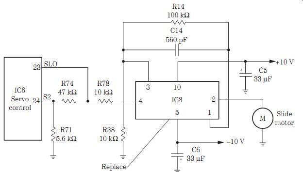
FIG. 19 A defective slide motor driver IC3 caused no rotation in a Pioneer
PD-7010 CD player.
A Fisher AD885 CD player would stop in the middle of a program and sometimes appear intermittent. A critical voltage test on the IC115 (7805) 5-V regulator revealed a very low voltage of 3.5 V. After replacing IC115, the voltage returned to normal at 5 V, and the CD player returned to normal operation.
No play, dead operation
No play, no power, and a dead CD player can be caused by many different components. A leaky or shorted diode in the low-voltage power supply can cause a trans former winding to open, resulting in no dc voltage on the large filter capacitors.
Notice if the display lights up. Make sure that the voltage from the low-voltage power supply is normal. A defective on/off switch or open fuse can cause a dead CD player.
Critical voltage measurements on all transistors or IC voltage regulators can cause motors, drivers, and servo circuits to fail (Fig. 20). Check for a leaky or open electrolytic filter capacitor for very low or no output voltage. Make sure that the dc-dc converter power supply is turning out the correct voltage.
Check the drive motor circuits when the drive motor will not operate. Measure the voltage to the drive motor from the transistor or IC driver stage. Measure the voltage (Vcc) applied to the drive motor transistor or IC. Often negative or positive voltage is applied to these components. Likewise, check the supply voltage of the servo or control processor for no drive motor rotation. Make sure that the EFM waveform is found at the RF IC. The CD player will shut down at once when there is no EFM waveform at the RF IC. This indicates a defective RF or optical pickup assembly.
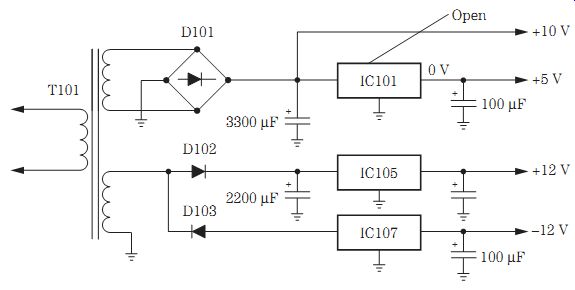
FIG. 20 A defective open IC101 caused no motor operation in the play mode
of a CD player.
Intermittent components within the power supply can cause intermittent operations.
Monitor the various sections of the power supply to determine where the intermittent component is located. Connect the voltmeter across the largest filter capacitor and notice if the voltage is constant or changes when the CD player becomes intermittent.
If the intermittent component is not in this section, proceed to the various voltage sources with the digital multimeter (DMM). Often the intermittent part is a transistor or IC voltage regulator. Monitor the voltage at the emitter terminal and output-regulated transistor voltage with the DMM. Inspect the transistor and IC regulator terminals for poorly soldered contacts. Check all filter capacitors (330 uF) in a Sony CDX120 CD player for dead, no power operation.
Noisy sounds
Hum in the sound can be caused by dried-up filter capacitors. Check each electrolytic with the ESR meter. Replace the D/A converter with background noise during the quiet play parts of the CD. Replace the RAM IC that produces a ticking sound when a CD is playing. Replace the optical pickup assembly for static heard while a CD is playing. A low-level noise can result from a defective crystal in the VCO circuits (Fig. 21).
Suspect IC components in the sound circuits when there is garbled audio. Distorted audio can be caused by a defective D/A converter IC. No audio can result from a faulty demodulator IC. A missing reference voltage from an IC regulator can cause intermit tent static and popping noises with no audio output. Check the D/A converter IC for static in both channels. Replace small decoupling capacitors (10 to 50 uF) when there is noisy audio. Excessive noise in the audio output when the power is turned on and there is no clock signal can be caused by a defective crystal in the VCO circuits. Garbled sound in a Sony CDPC5F model was caused by defective IC501 and IC503.
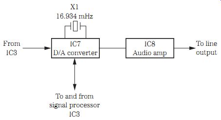
FIG. 21 A low-level noise can be caused by a defective VCO crystal in the
microprocessor.
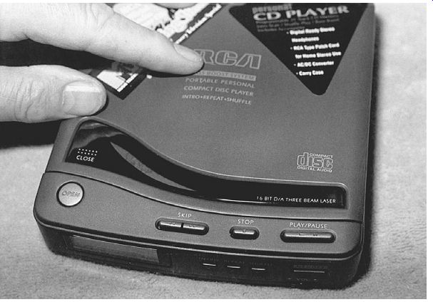
FIG. 22 The door or lid must be closed on a portable CD player before the
CD will spin.
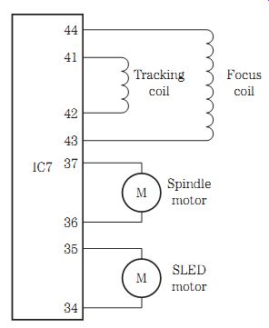
FIG. 23 IC7 drives both tracking and focus coils and both spindle and SLED
motors.
The portable CD player
The portable CD player was designed for the ardent, on-the-go music lover (Fig. FIG. 22). A portable CD player operates from batteries or a battery pack. A portable CD player has circuits similar to those of a large tabletop or changer CD player. Of course, there are only two motors, slide and disc motors, because the player features top loading. The motor circuits may be controlled by one IC. You can listen through a pair of headphones with either battery or ac operation. The portable CD player has two line output jacks to play through an external amp.
All portable CD players have a top-lid interlock switch system that provides protection for the operator when the top lid is opened for loading of CDs. The lid interlock switch disables the laser signal. Remember, the optical lens assembly shines upward to ward your eyes, so power to the laser diodes is removed when door is open.
The focus, tracking, and motor circuits in a Realistic CD-3370 player are controlled by IC7. The focus coils are connected to pins 43 and 44, whereas the tracking coil connects to pins 41 and 42. The focus coil test points are TP10 (F2) and TP12 (F1) (Fig. 23).
IC7 also provides drive for the spindle and SLED motors. The spindle motor connects to pins 36 and 37. The SLED motor terminals connect to pins 34 and 35. In this portable CD player, the coils and motors are controlled with one IC7 driver. The slide motor moves the laser assembly out on sliding rods, and the disc motor rotates the playing CD.
The portable CD player contains many surface-mounted device (SMD) components, gullwing ICs and microprocessors, and several PC boards. These small components, PC wiring, and parts make servicing portable CD players more difficult. More IC components are found in portable CD players because of their physical size. The suspected IC may control two or more different circuits. Check the supply voltage, and scope the signal in and out of the suspected IC. Take voltage and resistance measurements on each terminal pin before replacing an IC.
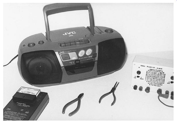
FIG. 24 A boom-box CD player also may have an AM/FM/MPX receiver and a cassette
player.
Boom-box CD circuits
The boom-box CD player comes in a number of large units and tabletop or portable players. Today, a CD player also may contain an AM/FM/MPX receiver, as well as CD and cassette players. Most boom-box players have top loading of the CDs without a loading motor. A rotating keeper at the top of the lid holds the CD in playing position.
A boom-box player will not play until the lid is locked down. Portable CD players can be operated from batteries or the ac power line (Fig. 24).
Most boom-box CD player circuits are the same as those of portable CD players, except that the components are not quite jammed together as much as in a portable CD player. A boom-box CD player can have preamp circuits that switch into the regular stereo cassette and radio amp circuits. You will find many SMD components within boom-box CD circuits. IC components are found throughout the CD player circuits, with only a few transistors within the mute circuits. The stereo signal from the D/A converter is switched into the input of the power output IC (Fig. 25).
The RF IC amp provides signals to a servo large-scale integration (LSI) as well as to the digital signal processor IC. The digital signal is sent to a D/A converter IC, with one audiofrequency (AF) amp IC serving both stereo channels. The servo IC controls one large IC driver that provides signal to the focus and tracking coils and disc and slide mo tor driver ICs. A large processor IC controls the LCD, signal processing, and servo LSI components. You may find 8 to 10 large ICs controlling all the circuits within a boom box CD player.
The power supply in a large boom-box CD player might be dc-dc converter circuits, whereas a smaller boom-box player may operate from a power line cord or an adaptor power supply. Usually, the power supply transformer voltage is rectified by a bridge rectifier component or separate silicon diodes, with a sliding switch applying dc voltage to the cassette, motor, receiver, and amplifier circuits. Sometimes the power supply may have transistors and IC regulator circuits with a 2200- to 3300- uF filter capacitor (Fig. 26).
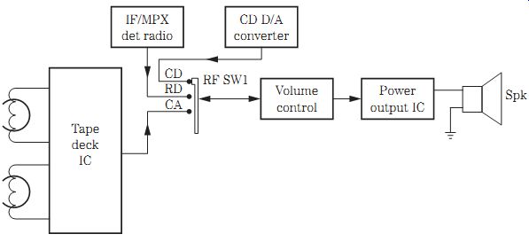
FIG. 25 Block diagram of boom-box switching to the audio amp circuits in a
combination tape deck, radio, and CD player.
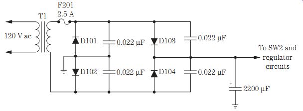
FIG. 26 A simple ac transformer power supply provides voltage to the receiver,
cassette, and CD circuits in a boom-box CD player.
Similar diagrams
If possible, try to locate a similar schematic when the correct diagram is not available.
A block diagram of a boom-box CD player, an auto CD player, or a portable CD player may help in isolating the problem and locating the defective part. Often universal ICs and processors are not provided for CD players. Use the original part numbers.
The defective CD motor
The slide or feed motor moves the optical pickup assembly, whereas the disc or spindle motor rotates the CD. Suspect a defective motor when the CD will not spin or the optical pickup assembly does not move. Most of these motors operate from a 5- to 12-V source.
The slide and spindle motors may operate from one motor driver IC. Often, the servo control IC provides signal to the motor driver IC, and the motors begin to operate (Fig. 27).
A defective CD motor may be open or intermittent. Check the dc voltage at the mo tor terminals when either motor is supposed to be operating. No voltage indicates a defective transistor or driver IC. Suspect a defective motor when normal voltage is present. Take a continuity test with the low-ohm scale of the DMM across the motor terminals. No measurement or a very high reading indicates that the motor should be re placed. Sometimes, by tapping the end of the motor with the handle of a screwdriver, the motor begins to spin; replace it anyway.
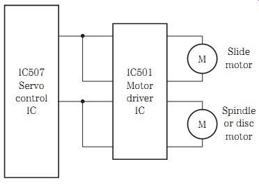
FIG. 27 Servo control IC507 provides signal to the driver IC501 and voltage
to the slide and spindle motors.
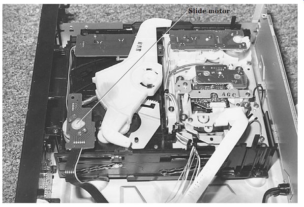
FIG. 28 A defective slide motor can result in no movement of the optical pickup
assembly.
An intermittent motor will cause intermittent CD rotation. A sticky slide motor can cause the optical pickup to keep skipping the track. The bad spindle motor can cause the pickup to skip the track. Intermittent voltage supplied to the motors can cause the pickup to skip the track or play only one portion of the CD. Check the table height of the disc motor when the tray will not spin, skips, and stops (Fig. 28).
Do not overlook defective parts that can keep the disc or slide motor from operating. Reposition the SLED gear when the CD starts skipping on the first track. Clean the limit switch when the CD skips on the first track. A chattering noise may result from poor gear meshing between the worm gear and the first gear. Suspect a bad plastic worm gear when mistracking and skipping occur. Replace the power switch when the pickup intermittently loses tracking after a few minutes. Replace the reset switch if the pickup skips at the beginning of a track.
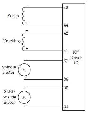
FIG. 29 A negative and a positive voltage is applied to the coils and motors
from a large driver IC7.
Clean and lubricate the guide rails when erratic skipping occurs. Wipe all foreign matter that might prevent the pickup from moving from the guide rails. Clean the lens assembly of dirt and dust that can cause the pickup to skip and jump tracks. An intermittent transistor or IC voltage regulator can cause intermittent motor operation by providing intermittent voltage to the motor driver IC circuits.
Motor drive circuits
Early CD players had transistors as motor drive components in the disc and spindle motor circuits. Today, the servo driver IC applies voltage to one large IC that drives the disc and SLED motors. The same driver IC also may drive the focus and tracking coils (Fig. 29).
Suspect a shorted or leaky driver IC when no or low voltage is applied to the motor terminals. Measure the supply voltage (Vcc) applied to the driver IC. A defective transistor or IC regulator may not apply the correct voltage to the driver IC. A low 1.5 to 3 V applied to the focus and tracking coils can make them move, indicating that the coil assemblies are okay. Apply a 5-V dc source to suspected motor terminals and notice if the motors take off. Transistor or IC driver motor components can appear open, leaky, intermittent, and shorted.
SMD components
Be very careful when taking voltage and resistance measurements on SMD ICs, processors, and transistors. Use a magnifying glass to get the correct terminal.
Sometimes these gull-like leads are so close together that its very easy to short two terminals together with regular test probes. Either sharpen the test probe to a fine point or purchase a pair of thin probe tips with leads.
The SMD signal processor might have 80 terminals. Usually the signal processor IC can be located as the one having the most terminals. The servo signal processor might have around 50 terminals. In portable CD players, you may find the focus, tracking, spindle, and slide motor circuits on one large IC having 44 or more terminals. Of course, this processor IC can be located by its PC board wiring connected to the motors, focus, and tracking coils.
Troubleshooting D/A circuits
Check at both the left and right stereo channels for the same amount of audio with an external audio amplifier. Improper or unbalanced audio may indicate a bad D/A converter IC. Go directly to the power supply when low or no voltage is found at the D/A converter IC. Remove the solder around the voltage supply pin with a solder wick and iron, or if it's an SMD D/A component, lift up the terminal as heat is applied from the soldering iron. Make sure that the supply pin is completely loose from the voltage PC trace. Suspect a leaky D/A converter IC if the dc voltage increases to its original value; replace the defective IC (Fig. 30).
Do not overlook a possible mute transistor that may be shorting out the audio from either channel to ground. Replace the D/A converter IC401 for no audio output in a Sony CDP101 CD player.

FIG. 30 Check the right audio output from the D/A converter (IC401) for a
weak, intermittent, or dead audio channel.
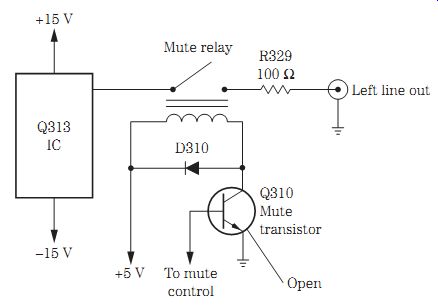
FIG. 31 An open mute transistor (Q310) prevented audio in the left channel
of an Onkyo CD player.
Defective mute system
Sound muting is often provided to suppress noise that is produced when the power is turned on. In some players, muting is automatic when the CD stops, during accessory operations, and during pause mode. The sound muting system contains transistors, ICs, and relays to cut out or ground out the music. Muting is also done in some line output jacks and in headphone circuits (Fig. 31).
A defective mute system can cause either a low or dead left or right audio output of the D/A converter. Suspect a defective mute system in the digital signal processor when both channels are weak. Check for a defective transistor when only one channel is weak or dead. Trace the audio output from the D/A converter to the line output jacks with the external audio amplifier or scope.
Disconnect the mute transistor emitter or collector terminal from the circuit with a weak or dead channel. Replace the defective mute transistor or IC when the audio re turns to normal. Replace the mechanism micro IC (8-759-971-41) in a Sony CDPC70 CD player for no muting during program mode.
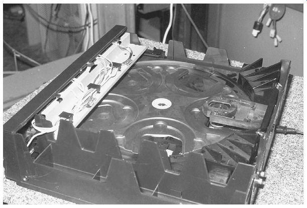
FIG. 32 The rotary tray in a Magnavox CDC745 tabletop CD changer selects the
correct CD for playing.
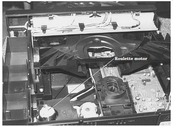
FIG. 33 The roulette motor turns the tray that contains several loaded CDs
in the CD changer.
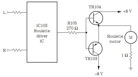
FIG. 34 TR103 and TR104 drive the roulette motor in an early CD changer.
The CD changer
A CD changer may be found in a home entertainment system, a portable boom-box, or an auto receiver with cassette and CD changer (Fig. 32). Usually an auto CD changer is found in the trunk. A boom-box CD player might have a three- or five-disc changer. An auto receiver may include a six-disc changer or more. The Philips HIFI system contains a three-disc changer, whereas the Panasonic has a 300-W five-CD mini-changer system. Sony keeps the music playing with its 60-disc storage mini HIFI CD changer audio system with 100 W.
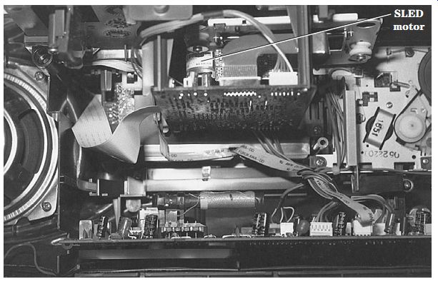
FIG. 35 The slide motor moves the pickup assembly on rails as the disc motor
rotates the CD in the playing mode.

FIG. 36 The loading motor has a different polarity voltage applied in loading
and unloading.
The tabletop or auto CD changer may contain five or six discs. The turntable or roulette motor rotates the tray holding the CDs and stops for the correct selection (Fig. FIG. 33). The roulette sensor circuits provide correct start and stop indicators for the roulette motor. The typical roulette motor may be controlled by transistors or ICs or a combination of both. A signal from pin 21 of system processor IC201 controls the transistors and ICs in the roulette motor circuits.
The roulette right and left input is applied to pins 5 and 6 of roulette motor driver IC103. IC103 provides a right and left voltage to the base of driver transistors TR103 and TR104. The reverse voltage applied to the base of each transistor can control the rotation of motor to the left or right. Voltage at the emitter terminals of TR103 and TR104 is applied directly to the roulette motor terminals through CB111 and CB103 (Fig. 34).
Most electronic circuits found in a CD changer are similar to those found in any large table-top CD player. The big difference is the four to six motors found in the CD changer player. A slide or SLED motor moves the optical assembly along the rails from the inside to the outside edge (Fig. 35). The loading motor loads the tray by moving it in and out. The roulette or select motor rotates the five or six discs in a turntable for selection. A disc or spindle motor rotates the CD at 500 to 200 rpm. The up/down mo tor assists in loading and playing of the CD, whereas the magazine or carousel motor rotates the turntable. In some CD changers the carousel, tray or loading, and turntable motors operate from the same microprocessor (system control) (Fig. 36).
You will find several different PC boards in a CD changer. A large board contains the ac power supply with voltage regulators, signal processors, and system control circuits, whereas the different motor circuits are tied to a servo control board. The servo control board has motor transistors and ICs that make the different motors operate. Removing the bottom cover may reveal the servo board and motors. The resistance of the SLED motors may range between 10 and 20 ohms; roulette motors, 15 and 18 ohms; and loading motors, 5 and 20 ohms. Check continuity or motor resistance when voltage is applied at the motor terminals and the motor does not rotate.
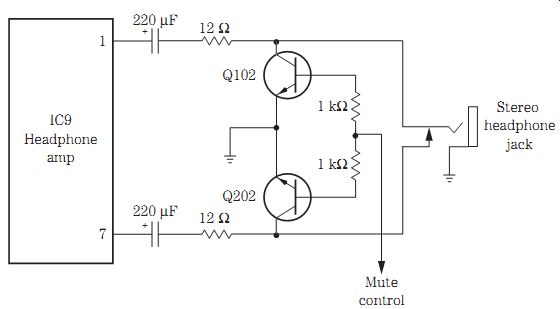
FIG. 37 Q102 and Q202 provide muting in the headphone amp output to a stereo
headphone jack.
Servicing headphone circuits
Headphone amplifier circuits can be signal traced with an external audio amp. Often the headphone amplifier connects to the audio signal before the line output transistors. The audio is amplified by one or two separate IC amp drivers. You might find one large IC for both channels in portable CD players.
The audio is fed to a dual volume control and input circuits of the headphone driver amp. The amplified audio is capacity coupled to the earphone jack with two muting transistors in the stereo channels (Fig. 37).
Signal trace the audio in and out of the headphone driver IC. Suspect the driver IC or defective mute circuits when both channels are dead. With one defective audio channel, suspect a mute transistor, coupling capacitor, or driver IC. Take voltage measurements on the driver IC to determine if the IC is defective. Remove the collector terminal of the dead or weak channel's mute transistor. Locate the driver IC by tracing the PC board wiring from the jack to the first component.
Troubleshooting servo circuits
The servo processor provides power to the tracking and focus coil, spindle, and slide motors through respective IC or transistor devices. The servo IC must receive tracking error (TE), focus error (FE), and mirror data and focus okay (FOK), interface, system control, and clock data from the system control IC before the various circuits can function. The data latch, phase comparator input, VCO, spindle motor drive, and spindle motor on/off control signal from the digital processor are then routed to the input servo processor.
Improper operation of these functions may point to a defective servo control IC.
Take critical voltage tests on each terminal pin. Locate the servo processor IC as the one with 40 or more pin terminals.
Check the focus and tracking coils with continuity ohmmeter tests when there is no or improper focus and tracking action. Measure the voltage on each driver transistor or IC. Take critical waveforms at each focus or driver IC.
When either the spindle or SLED motor will not function, take motor continuity tests with an ohmmeter. Measure the voltage at the motor terminals. Take critical voltage measurements on each driver IC or transistor. Scope the motor control and driver IC. Locate the driver and control IC by tracing the motor PC board wiring back to the first driver IC.
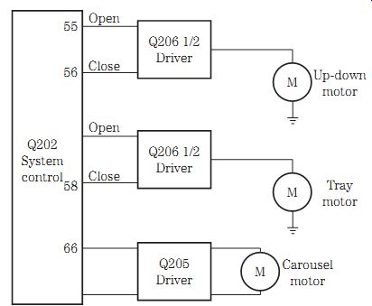
FIG. 38 A system control IC (Q202) drives the up and down tray and carousel
motors in a CD player.
Loading problems
The loading motor moves the tray out to be loaded with the CD and then returns into the player. Usually the tray is driven by a plastic gear box next to the tray assembly.
A clamper or flapper assembly may operate when the tray is loading and unloading in some CD players. As the tray is closing, the clamper places a spring-loaded pressure on the CD, holding the disc in position up a disc spindle. The loading motor operates from a motor driver transistor or IC. Different polarity voltages are applied to the loading motor driver IC from a large microprocessor (Fig. 38).
A dirty open/close switch can cause intermittent or erratic tray operation. If the tray will not open, check all possible mechanical problems first. Visually inspect the drawer gear assembly for foreign objects. Notice if the tray rails or gears are binding.
Clean the rails and gears, and then apply a light coat of lubricant to the sliding areas.
Clean them with alcohol and a cloth, and lube with a light oil or grease.
Suspect a defective photo interrupter when the drawer will not load. Improper voltage to the loading motor can be caused by a shorted electrolytic capacitor in the power source. Clean the leaf switch for intermittent loading and unloading of CDs.
Do not overlook a broken or cracked loading motor belt when a CD will not load. Listen for the rotation of the loading motor. Replace the loading motor drive belt when it is loose or cracked. Replace the motor for intermittent or no loading of CDs. Sometimes a jammed gear will not let the motor rotate. The tray would not move back and forth in a Magnavox MX3702 CD player as a result of a short in the C04 (470- uF, 10-V) electrolytic capacitor.
Actual CD case histories
The CD starts and stops in the middle of the program, and this was caused by IC115 (7805), a 5-V regulator with voltage down to 3.9 V in a Fisher AD885 CD player. Improper tracking was caused by a split groove gear in a Onkyo DX530 model. Some times the player was inoperative and would not play the outer track, and this was caused by a bad ribbon cable on the laser head assembly to the main PC board in a Pioneer PDM501 model. No audio in the left channel of an Aiwa DXM77 CD player was caused by a defective low-pass filter (LPF101).
A background noise during the quiet parts of music was caused by a defective D/A converter (IC302) in a Sony CDP203 CD player. Inoperative functions in a Sony CFD460 player with an okay display were caused by a defective flameproof R306 (1.5 ohm) resistor. Resolder all connections on the regulator transistors for intermittent sound and clicking of the protection relay in a Pioneer SX880 CD player. Replace the 14-V zener diode when the protection relay will not turn on the speakers in a Pioneer SX750 CD player.
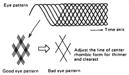
FIG. 39 With a dead or inoperative CD player, check for an EFM waveform at
first.
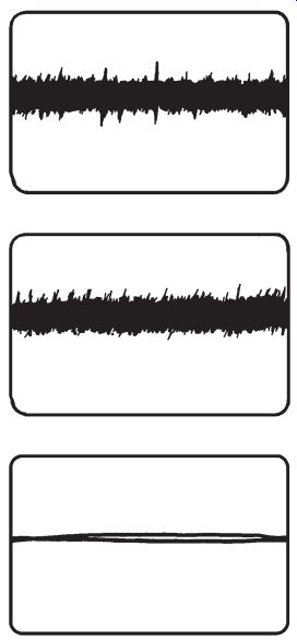
FIG. 40 A focus waveform taken across the focus coil winding.
FIG. 41 A tracking gain waveform taken across the tracking coil winding.
FIG. 42 The motor waveform is kind of flat but moves when the motor rotates.
Critical waveforms
One of the most critical waveforms is the RF EFM from the optical pickup assembly and the RF amplifier. The weak signal from the laser assembly is amplified by transistors or an IC component. Take a quick waveform with the scope at the output terminal of the RF amp before checking any other parts on an inoperative or dead CD player. Often a defective optical pickup assembly determines if the cost is too expensive to finish servicing the rest of the CD player (Fig. 39).
The focus gain waveform taken right off the focus coil can indicate if the focus circuits are functioning. Although the focus waveform is not too high, a very narrow or straight line would indicate that the focus circuits are dead (Fig. 40). The focus wave form might fail if the focus gain control is set too small.
A tracking gain waveform across the tracking coil will determine if the tracking coil and circuits are working. Connect the scope probe across the tracking coil winding. Play a test CD. If the sound jumps when the machine is jolted or bumped, the tracking gain control might be set too close or too small. If a test CD with a small scratch is played and the audio jumps, the tracking gain may be set too large (Fig. 41).
Take a waveform across the slide, carriage, or SLED motor with the scope. The mo tor waveform will move slightly up and down when the motor is rotating (Fig. 42).
To determine if the VCO is performing, locate the VCO crystal and take a scope waveform from one side of the crystal. This waveform will show that the microprocessor is functioning (Fig. 43).
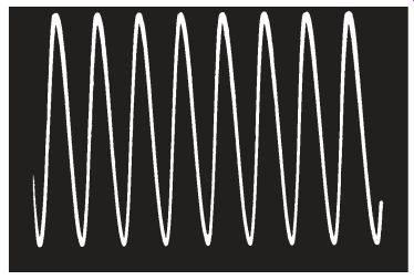
FIG. 43 A VCO waveform taken from the crystal on the microprocessor.
For additional troubleshooting tips, see Table 1.

Table 1. CD player troubleshooting.
=============
Symptom Remedy
Dead Check for the open fuse.
Check the fuse holder.
Check for an open transistor or IC regulator.
Check the various voltage sources.
Keeps blowing fuse Check for a leaky transistor regulator.
Check for a leaky audio output transistor or IC.
Check for a leaky filter capacitor.
Check for a defective voltage source.
Check for a burned fuse cable and harness.
No light display Check for defective power sources.
Check for no negative voltage to display.
Check for a defective display circuit.
No loading Check loading motor operation.
Check to see if the motor belt is off.
Check for foreign objects in gear operation.
Check for a jammed belt.
Check for voltage across loading motor.
Check binding loading mechanism.
Will not eject Check the solenoid or plunger mechanism.
Check the voltage at the plunger solenoid.
Check the eject mechanism .
Starts up and shuts down Quickly scope for the RF or EFM waveform.
Notice if the focus and tracking are searching.
If there is no RF waveform, check the RF amp.
Check the laser diode with a power meter.
Check the servo loop.
No disc movement Check the defective EFM.
Check for a defective spindle circuit.
Check the voltage on the spindle motor.
Check for a defective transistor or IC driver.
Check the servo or signal-processor circuits.
No disc rotation in playback Has focus been locked? Check for a defective mechanism.
Has the tracking closed? Check for a defective tracking mechanism.
Check the EFM.
Check the spindle or disc motor circuits.
Search operations abnormal Check the EFM waveform.
Check the voltage at the carriage or SLED drive voltage.
Check the waveform at the carriage or SLED motor.
Check for motor voltage at the terminals.
Check the carriage or SLED motor.
Suspect motor driver transistor or IC.
Check the servo loop circuits.
No sound Does the disc rotate? Has the focus been locked? Check for normal EFM.
Check for sound at the output of D/A.
Check the audio amp circuits.
Check the headphone circuits.
Noisy sound Check the sound circuits.
Suspect a noisy output IC or transistor.
Check the D/A converter circuits.
Defective audio output circuits.
============