The TV chassis has come a long way since the 6- by 10-in black-and-white table model was first introduced on the market. Today, the screen size on a direct view TV has increased to a 32- to 35-in cathode-ray tube (CRT), flat screens from 15 in on up, projection TVs of 61 to 65 in, and plasma TVs from 42 to 60 in. High-definition TVs (HDTVs) have screens that range from 43 to 65 in. Besides all the TV circuits, today's TVs may have VCR and DVD players within the same unit.
TV chassis components
Most TV chassis have a tuner; an intermediate frequency (IF) section; synchronization (sync), automatic gain, horizontal, vertical, chroma, and luma controls; high- and low-voltage power supplies; and sound circuits (Fig. 1). Before tearing the TV chassis apart and jumping into troubleshooting, check the symptoms. Do you have a raster? Is the picture pulled up from the bottom. Do you have sound but no picture or raster? Start with the symptom apparent on the picture tube or heard in the speaker. Use your eyes, ears, and nose to help troubleshoot the TV chassis.
No raster or high voltage may cause problems in the horizontal or high-voltage circuits. No raster, no picture, or no sound can be caused by failure of the low voltage power supply. Hum in the sound and hum bars in the picture may result from dried-up or open filter capacitors in the power supply or a leaky voltage regulator.
Only a horizontal white line indicates a defective component within the vertical circuits, and on it goes.

FIG. 1 Block diagram of the vertical and horizontal deflection circuits in
a TV.
You can hear a frying noise in the sound, which indicates a defective transistor, integrated circuit (IC), or ceramic bypass capacitor. A tic-tic-tic in the flyback indicates problems within the horizontal output and flyback circuits. The arc-over of a spark gap on the CRT may be caused by excessive dust and dirt in the gap area or too high a voltage. A cracking and arcing around the anode terminal of the CRT may result from excessive high voltage or poor rubber insulation of the anode button.
The most troubled sections
Most of the troubles found in a TV are in the horizontal, vertical, and low-voltage power supplies. Nothing operates in a TV with a defective power supply because the power supply provides voltage to most of the TV circuits. The most troublesome section is the horizontal circuits, which provide sweep, high-voltage, linearity, and secondary voltage circuits. Today, the horizontal circuits must function before sup ply voltages are developed in the flyback or horizontal output transformer circuits, providing voltage to many other circuits in the TV chassis. The TV low-voltage power supply circuits are discussed in Section 9.
Next most troublesome are the vertical circuits. The vertical section provides vertical sweep to the yoke and picture tube circuits. About 85 percent of the troubles found in a TV chassis are located within the horizontal and vertical circuits (Fig. 2).
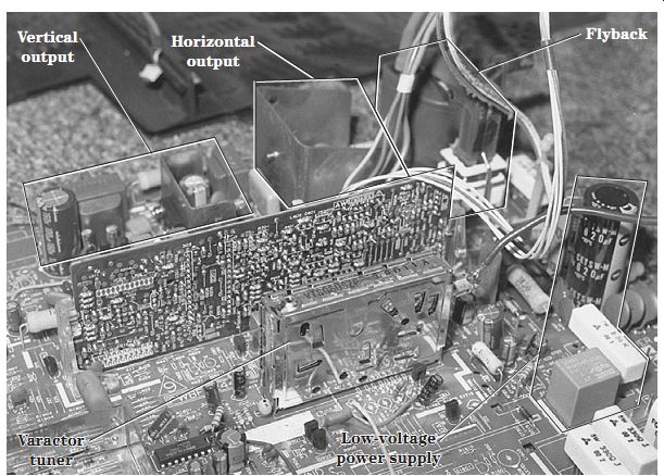
FIG. 2 Locations of the various stages within a color TV chassis.
Locating TV components
After determining the symptoms, isolate the defective section on the chassis. If the symptom points to the horizontal and flyback section, locate the flyback and horizontal output transistor on a heat sink. Remember, the regulator, vertical output, and horizontal output transistors may look alike. Extremely high dc voltage on the regulator and output transistors separates away from the vertical circuits. A scope waveform on the horizontal output transistor and mounted close to a driver trans former locates the horizontal output transistor.
Likewise, the vertical output transistors are found mounted on separate heat sinks.
The vertical power output IC is found on a heat sink, and it is much fatter and longer compared with the line voltage regulator. Both the vertical and horizontal sweep signals are found in a large deflection IC with other circuits. Horizontal and vertical circuits are located easily on a TV chassis. Check the numbers and letters on top of the IC, and look them up in the semiconductor manual for the correct sweep IC.

FIG. 3 The TV is turned on by a relay controlled by IC101 micon.
Relay problems
The relay found in the input circuits of a TV may turn the set on or degauss the picture tube. An open relay solenoid can cause no power. Intermittent turn on and off can be caused by a poorly soldered connection on the solenoid winding. A defective relay driver transistor can cause no turn-on operation. The relay will not click when there is an open relay driver transistor or solenoid.
When the relay does not click with a dead chassis, suspect an open relay coil, bad electrolytic capacitors in the relay circuit, or a damaged relay. Suspect defective relay point contacts stuck in one position when the TV cannot be turned off. Check for a defective relay driver transistor with the diode tester of the digital multimeter (DMM) when the relay will not click and the TV will not shut off. A shorted or leaky diode across the solenoid winding prevents relay action. Remove one end of the diode from the circuit, and check it on the diode tester of the DMM.
Intermittent shutoff or intermittent turn-on can be caused by dirty or bad relay switching points. The relay driver transistor can cause intermittent shutoff operation. Check all relay connections, and resolder them when there is intermittent relay action. Check all electrolytics with the equivalent series resistance (ESR) meter when the relay begins to chatter. Low voltage from the power supply and relay chatter may be caused by a bad filter capacitor. Intermittent startup can result from a defective relay. The chassis can be intermittently dead, and this also is caused by a defective relay. When a TV intermittently goes off and comes back on by itself, this also can result from a bad relay (Fig. 3).
Horizontal circuits
The horizontal sweep circuits start with a horizontal oscillator and countdown or deflection circuits. The horizontal drive waveform is coupled to the driver or buffer transistor and to a horizontal driver transformer. The secondary winding of the driver transformer is coupled to the base circuit of the horizontal output transistor.
The horizontal output transistor provides horizontal sweep to the yoke assembly and also develops the high voltage within the flyback. High-voltage diodes are found in the flyback windings within the integrated high-voltage transformer (IHVT) that supplies high voltage to the anode terminal of the CRT.
Horizontal circuit problems
Many different horizontal problems and interesting circuits are found in the horizontal circuits. The horizontal oscillator circuits can cause no sweep, horizontal drifting, and off-frequency symptoms. The oscillator circuits may be contained in one IC or transistor, or all horizontal circuits may be found in one large IC. The countdown circuits in the TV chassis provide both vertical and horizontal sweep circuits.
The horizontal driver transistor takes a weak drive signal and amplifies it, and the transformer couples the drive signal to the base of the horizontal output transistor. A leaky driver transistor can damage the primary winding of the driver transformer or voltage-dropping resistor, causing chassis shutdown. If the horizontal drive voltage is left off the base terminal of the horizontal output transistor too long, the output transistor also can be damaged.
The TV chassis can be dead when there is a shorted or leaky horizontal output transistor. Often the horizontal output transistor becomes shorted or leaky between the collector and emitter elements. Erratic TV startup and shutdown can result from poorly soldered connections on the horizontal driver transformer.
Horizontal bars in the picture may be caused by the horizontal oscillator being off frequency as a result of poorly soldered deflection IC terminals or defective filter capacitors. Poor horizontal width can result from a leaky or defective output transistor, improper drive pulse, and improper voltage supplied by a line voltage regulator IC (Fig. 4). Horizontal foldover can be caused by leaky bypass capacitors in the pincushion circuits, a change in resistance, and poorly soldered joints on the flyback.
Horizontal tearing can be caused by poorly soldered joints on the horizontal driver transformer, zener diodes in the fail-safe circuits, high-voltage capacitors in the flyback circuits, and electrolytic and safety capacitors. The tic-tic noise can result from a bad socket connection on the horizontal transistor or emitter resistor, a badly soldered joint on the output transistor, or a badly soldered connection on the horizontal driver transistor (Fig. 5).

FIG. 4 A defective line voltage regulator can cause dead, intermittent, and
shutdown symptoms in a TV.

FIG. 5 Locate the horizontal circuits by locating the flyback and horizontal
output transistor on a metal heat sink.

FIG. 6 A dead RCA CTC167 chassis tries to start up several times with a defective
Q4401 and poorly soldered terminals on the driver transformer T4301.
A dead chassis can be caused by an open fuse, no relay operation, bad relay contacts, improper voltage from the power source, a defective chopper transistor or line voltage regulator, a bad yoke, poorly soldered connections on the flyback, defective electrolytics, and open fusible resistors. A dead chassis can be caused by just about any component within the horizontal or low-voltage power supply circuits, and on it goes.
Go directly to the horizontal output transistor when the line fuse keeps blowing or the chassis will not start up. Check the resistance from the collector terminal (body) of the output transistor to the chassis ground. A low resistance on the DMM indicates a leaky transistor or damper diode. In the latest TV chassis, you might find the damper diode built inside the horizontal output transistor. An open output transistor may have high dc voltage at the collector terminal with no high voltage or sweep. In some Sears and Sanyo TV chassis, the metal body of the output transistor may not be the collector terminal.
A leaky horizontal output transistor can cause chassis shutdown, open both fuses, overload the low-voltage power supply circuits, or destroy the flyback. Likewise, a leaky or arc-over flyback or output transformer can destroy the horizontal output transistor.
Always check the damper diode when replacing a leaky output transistor. Improper or no horizontal drive signal can destroy the horizontal output transistor. When checking for a horizontal output waveform, hold the scope probe next to the flyback.
Always use a variable isolation transformer when servicing the horizontal circuits.
After replacing the leaky output transistor and checking the horizontal circuits, apply about 65 V ac from the variable transformer. Check the base of the output transistor for a drive waveform and dc voltage at the collector terminal or flyback. If the transistor appears warm, shut down the chassis and check for improper line voltage, a leaky fly back, or overloaded circuits. Keep raising the line voltage if the voltage and waveforms appear normal at the base of the output transistor (Fig. 6).
What keeps destroying the horizontal output? The horizontal output transistor (HOT) can be destroyed by improper drive voltage from the horizontal circuits. An arcing or leaky yoke assembly also can destroy the HOT. A grounded flyback winding also can destroy the HOT. A defective safety capacitor can cause the HOT to fail after several minutes. Poorly soldered terminals on the driver transformer can destroy the HOT. A defective bonded picture tube can destroy the HOT after the transistor has been replaced.
Shorted or leaky bypass capacitors in the yoke circuits can damage the HOT. Resolder all terminals on the driver transformer. Check for open electrolytic bypass capacitors in the driver transformer circuits. Measure the resistance of a resistor that is in series with the B1 voltage source and primary winding of the driver transformer for correct resistance. Resolder all voltage resistor terminals on the printed circuit (PC) board (Fig. 7).
In an RCA CTC169 chassis, the HOT would blow as it was installed. The base wave form was fairly accurate when Q4401 was out of the socket. All components were checked in the safety circuits. C4403 was replaced because it kept destroying Q4401 (Fig. 8).

FIG. 7 Check T401 soldered contacts, R437, R436, and C435 for repeated failure
of Q401 in an Emerson TC2555D TV.
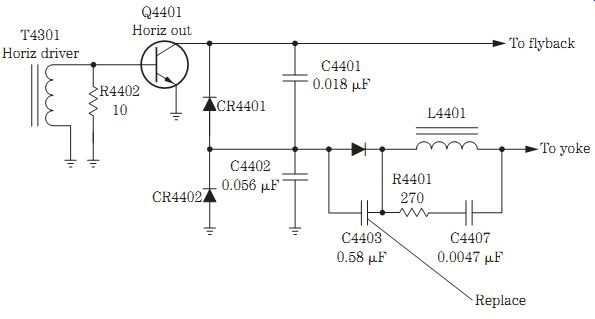
FIG. 8 Replace the C403 (0.58- uF) capacitor in the safety circuit of the
RCA CTC169 chassis that keeps destroying Q4401.
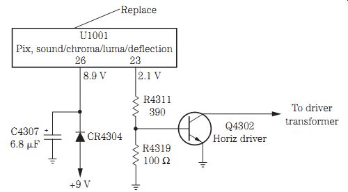
FIG. 9 U1001 was found defective with no horizontal waveform and with an injection
of 9 V at CR4304 in an RCA F35750STFM.
Old faithful replacement
Determine what causes failure of the HOT once it has been replaced and is damaged at once. Often the HOT becomes shorted or leaky between the collector and emitter terminals. Always resolder all driver and flyback transformer terminals. Try to replace the HOT with the original part number, if possible.
If the original is not available, look up the part number stamped on the body of the transistor in a semiconductor manual to provide the correct universal replacement.
Sams Photofacts provides universal replacements for a horizontal transistor. For in stance, in a Goldstar CMT-2612 TV, the horizontal output transistor Q402 (2SD1879) can be replaced with an NTE2331 or ECG2331 or an RCA SK10088.
Horizontal output problems
Go directly to the horizontal oscillator, countdown, or deflection IC with no wave form at the HOT. Locate the multiple-function IC that has picture, sound, chroma, luma, and deflection circuits. Scope each terminal of the IC for a horizontal square wave. If there is no square-wave output on the base terminal driver transistor, check the supply voltage pin terminal of the IC. Measure the voltage supplied (Vcc) to the deflection IC.
Today, you may find that the dc power supply is provided by a winding and diode within the secondary windings of the flyback. This means that the horizontal circuits must function before any supply voltage can be obtained or found on the deflection IC.
In the early TV chassis, the supply voltage was taken from the low-voltage power sup ply, and now it has been changed.
To determine if the deflection IC is okay, inject a dc voltage at this supply pin from the external power supply. At the same time, monitor the drive waveform at the deflection IC or at the base of the horizontal driver transistor. Slowly raise the dc voltage, if it is not known from a schematic, and watch the drive square wave on the scope. The dc supply voltage may vary from 7.5 to 25 V. If a square wave is found with the injected voltage, you may assume that the deflection IC and circuits are normal (Fig. 9). Suspect that the deflection IC is defective or components within the IC deflection circuits are bad when there is no waveform.
Horizontal voltage injection
When the oscillator sweep circuits are powered by a derived dc voltage from the horizontal output transformer, apply dc voltage to the supply terminal from an external power supply. Usually this voltage is from 7.5 to 20 V. Try a 10-, 12-, 18-, or 20-V source, and slowly bring the voltage up to get the correct waveform from the IC. You can use one or more 9-V batteries in series to reach the required voltage.
Attach the voltage source to the Vcc supply pin and common chassis ground. Solder in a piece of hookup wire, if necessary, to make a good connection and not short out other pin terminals. Pull the ac cord from the power plug for this test. Apply voltage from an external power supply, and scope the sweep output terminals. Locate the output terminal by tracing the wiring from the driver transistor base terminal.
If the waveform is normal at the sweep IC, you can assume that the horizontal IC is normal. When a weak or no waveform is found at the countdown or oscillator IC, suspect that the IC is bad. Suspect a leaky IC if the voltage goes below half the external dc voltage. Remove and replace the defective IC.
Safety first
When the high voltage arcs over on the CRT at the button terminal with a loud cracking sound, suspect that the high voltage is way over the limit. Excessive arcing can appear inside the flyback of high-voltage diodes and may not be caused by excessive high voltage at the picture tube. Safety or hold-down capacitors within the horizontal output collector circuits to the flyback can go open or have a cracked or loose terminal. Often these safety capacitors range from 0.016 to 0.056 uF and have a voltage rating of 1.6 or 2 kV. You may find silicon diodes within the same hold-down circuits.
Try to replace the safety capacitors with the same capacity and working voltage of 2 kV (Fig. 10).
Be very careful when measuring the high voltage with the high-voltage meter probe. Replace the safety capacitor first. A defective safety capacitor can let the TV come on momentarily with high voltage and shut down at once. Suspect the safety capacitor when the TV is only on for a few minutes. Often the safety capacitor end terminal will crack loose and then allow the high voltage to exceed the limits of the CRT. A shorted safety capacitor can cause a dead TV chassis.
A defective safety capacitor also can cause horizontal lines on the screen before the TV shuts down. The high voltage may come on momentarily, the degaussing relay then kicks on and off, and then the TV shuts down. The TV may operate for 10 to 15 minutes and then shut down; this is caused by one or more bad safety capacitors. Intermittent horizontal tearing also can be caused by a defective safety capacitor.

FIG. 10 An open or loss of capacity of a safety capacitor will let the high
voltage exceed the limit of the TV chassis.
Pulled in on the sides
Poor width can be caused by defective components in the horizontal, flyback, high voltage, and low-voltage circuits. Check the high-voltage regulator circuits when there is poor width in a late-model TV chassis. The high-voltage regulator transistor, silicon-controlled rectifiers (SCRs), and zener diodes in the regulator circuits can produce insufficient width. Poorly soldered connections on the pincushion, regulator, and driver transformers can result in poor width. Open bypass or coupling capacitors in the horizontal and high-voltage circuits also can cause poor width.
Low high voltage at the anode terminal of the picture tube can result in poor width.
Of course, this low high voltage may result from a defective component in the horizontal output circuit. Low drive voltage on the base of the horizontal output transistor can cause the transistor to become quite warm and produce a narrow picture. A low voltage source applied to the horizontal output circuits can cause poor width. Check the low-voltage source for a leaky regulator transistor, zener diode, or filter capacitor.
Check the safety capacitors when the raster is shrunk on both sides of the screen.
Replace the defective line voltage regulator with the raster pulled in 1/4 in on the sides.
A defective fusible resistor and voltage regulator can cause the picture to shrink on both sides and at the top and bottom. Poor width on both sides can be caused by a 5.6-ohm, 2-W resistor. Re-solder all terminals on the horizontal driver transformer for intermittent shrinkage on both sides of the raster (Fig. 11). Poor contacts on the yoke socket can cause shrinkage on both sides of the picture. Replace D805 off of pin 2 of the STR3115 regulator for a picture that is shrunk on both sides in a Goldstar CWR-4200 TV.
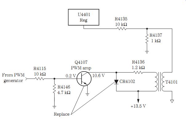
FIG. 11 The raster was shrunk at the top, bottom, and on both sides, and it
was caused by defective CR4102 and Q4107.
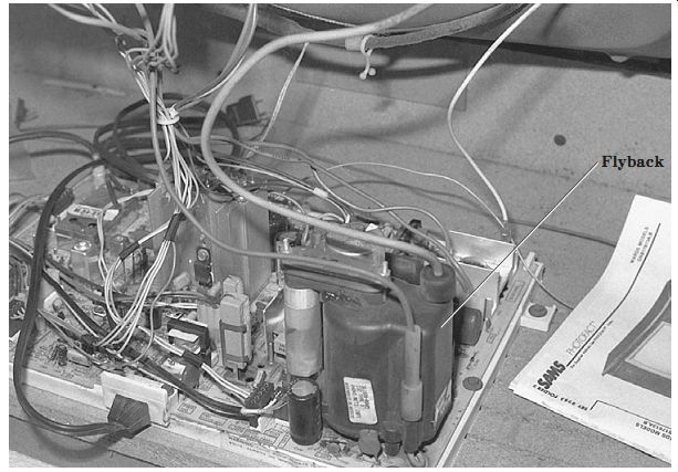
FIG. 12 A defective flyback can destroy the horizontal output transistor (HOT).
Flyback problems
The flyback or horizontal output transformer supplies high voltage to the picture tube, focus voltage, and low voltage from secondary voltage sources. Separate windings on the secondary of the flyback provide different voltage sources with diodes and filter capacitors. A defective flyback can destroy the HOT. Replace the flyback when the HOT keeps shorting out or becomes leaky after replacement. The shorted fly back can destroy the HOT and produce a chassis shutdown symptom. A defective flyback can destroy fuses and low-ohm resistors and cause a dead chassis. An arcing fly back can destroy the HOT (Fig. 12).
Intermittent horizontal sweep can result from poorly soldered terminals on pins 1 and 2 of the flyback. Resolder all flyback pin terminals for a dead or intermittent startup symptom. Check for a leaky HOT and poorly soldered joints on terminals 1, 2, and 10 of the flyback when a whining noise is heard from the switch-mode power supply (SMPS) circuits. Poorly soldered joints on the flyback terminals can cause the chassis to be intermittent or to go off-frequency. Suspect the flyback when the chassis tries to start up momentarily and then shuts off. An open 1.6-ohm, 2-W resistor on line with pin 9 of the flyback can cause no raster, CRT filaments not lit, audio okay, and high voltage normal.
The TV chassis may shut off after operating for 1 hour, and this is caused by a bad fly back. When the audio was okay but the chassis smokes, this also may result from a bad flyback. Suspect a defective flyback when the relay clicks on and then off, and the chassis goes dead. Immediate shutdown can result from a bad flyback. When the TV comes on briefly and then shuts off, this also can be caused by a defective flyback. Open windings between pins 2 and 3 can produce no vertical sweep. When the power switch is activated and a click followed by another click is heard and the set goes dead, this is caused by a bad horizontal output transformer.
A dead TV with a chirping noise can be caused by a defective flyback. Arcing noise followed by smoke also can result from a bad flyback. When the TV makes a popping noise and then shuts down, this is caused by a defective flyback and HOT.
Suspect a bad flyback when the chassis will not start up. Very low high voltage of 10 kV can be caused by a bad flyback. A defective flyback may cause the chassis to come on with a tic-tic noise and then go into shutdown. Replace the flyback when noise is heard form it. A bad flyback can cause a no raster symptom with normal audio in the speakers. A bad flyback may cause a dead chassis that tries to start up with a clicking noise. A bad flyback may arc over from windings to the metal strap and core with a noisy cracking sound (Fig. 13).
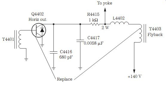
FIG. 13 A GE CTCC146D chassis was dead with a blown fuse caused by a leaky
horizontal output transistor (Q4402) and flyback.
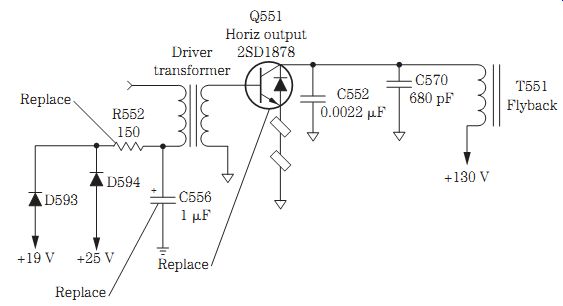
FIG. 14 The R552 (150-ohm, 3-W) resistor, the C556 (1- uF) electrolytic, Q551,
and all the driver transformer connections were re-soldered after being
installed for a second time, and Q551 was running red hot.
Red-hot output transistor
A Mitsubishi CS-2656R model TV was dead with no picture, no sound, and no high voltage. Right away the HOT was checked, and there was a short between the collector and emitter terminals. Q551 was replaced with another 2SD1878 transistor.
The picture came on immediately, and within minutes, the chassis shut down. Q551 was red hot (Fig. 14).
Before replacing Q551 once again, the terminals were re-soldered on the driver transformer (T552). R552 had run very warm and was replaced. Both diodes D593 and D594 tested normal. When C556 was checked with the ESR meter, the small 1- uF electrolytic registered in the red zone. C556 was replaced.
Continuity tests on the primary and secondary windings of T552 were fairly normal.
All connections on R552, C556, and T552 were re-soldered. Hoping that the flyback was normal, another horizontal transistor was installed. The chassis came on, everything looked good, and the chassis ran for 8 hours with Q551 only running lukewarm.

FIG. 15 The defective yoke can destroy the output transistor, arc over, have
open windings, and become intermittent when it has badly soldered connections.
Yoke problems
An open yoke winding in the horizontal sweep circuits can cause a white vertical line on the CRT. Likewise, an open vertical winding in the yoke can cause a white horizontal line on the TV screen. A bad yoke can cause the set to come on momentarily and then smoke and shut down. The defective yoke can blow the main or secondary fuse. A poor yoke socket connection can result in intermittent horizontal or vertical sweep. Arcing lines in the picture can be caused by a bad yoke assembly. The defective yoke can burn, smoke, and create a bad smell when the chassis starts up (Fig. 15).
Immediate chassis shutdown can be caused by a badly soldered yoke joint or a bad yoke assembly. The TV can come on for a minute and then smoke with no horizontal sweep when it has a bad yoke. Shrinkage from both sides of the screen can result from corroded yoke terminal contacts. You may find the chassis dead with a relay click when there is a leaky HOT and 10-ohm, 3-W resistor and a defective yoke assembly.
The arcing or leaky yoke can keep destroying the HOT. A buzzing or frying sound can be cause by arcing internally within the yoke assembly. A bad yoke may need to be replaced when a noise is heard at startup. A loud squealing noise may result from a badly soldered joint on the yoke terminal connections.
The defective yoke can cause only 4 or 5 in of vertical sweep. A bad yoke also can cause the horizontal output transistor to run red hot. Sometimes the dead chassis relay may click off and on with a bad yoke and line voltage regulator (STR30130). A badly soldered joint or trace on the yoke assembly plug can cause intermittent play or a complete loss of vertical sweep.
A JVC AV-2779S TV was dead when the relay clicked on and then off. The HOT (Q552) was found to be leaky and was replaced with a 2SD1556 replacement. After the transistor was installed, it began to run red hot and was pulling heavy current even when the power line voltage was around 82 V ac. Replacing the yoke assembly solved the problem.
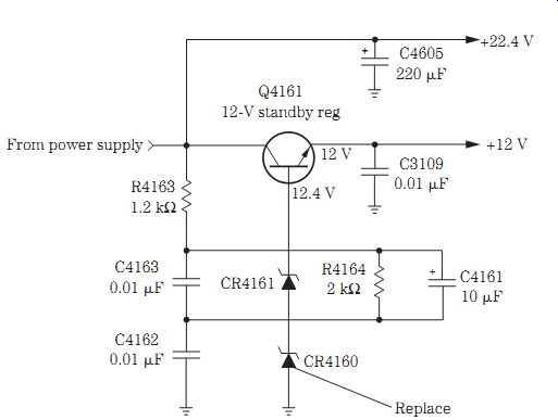
FIG. 16 Intermittent shutdown was caused by a zener diode (CR4160) in an RCA
CTC167 chassis.
Intermittent shutdown
Intermittent shutdown in the horizontal section can be caused by intermittent transistors, ICs, and driver and flyback transformers. Monitor the base terminal of the HOT with the scope, and notice when the intermittence occurs. If the waveform comes and goes, suspect that the intermittent problem is in the driver or deflection circuits. If the chassis shuts down intermittently and the waveform is normal on the HOT, you can assume that the intermittent component is in the output, flyback, or high-voltage circuit.
A bad flyback can momentarily start up the TV chassis and then shut it down.
Check all electrolytics with the ESR meter (10 to 100 uF) for shutdown after the chassis operates for 15 or 20 minutes. Also check all electrolytics with the ESR meter for virtually immediate shutdown. A bad relay can shut down the chassis immediately. An arc-over on the CRT anode button can cause the set to turn on with a snapping noise and then shut down. Clean around the high-voltage anode button with alcohol and a cloth. An arcing flyback can cause the chassis to shut down.
Check for defective 2200-pF, 2-kV bypass capacitors when there is immediate shut down. Suspect large filter capacitors (470 uF on up) when the set shuts off intermittently as it tries to start up. Leaky diodes can cause the TV to come on and shut off immediately (Fig. 16). The TV chassis can shut off when there are badly soldered joints on the driver transformer terminals. Badly soldered joints on the transistor regulators cam intermittently shut the chassis off and on. A badly soldered joint on the relay can cause intermittent chassis shutoff.
Suspect bypass capacitors in the safety hold circuits (680 pF, 2 kV) when high voltage comes up followed by immediate shutdown. When the TV shuts down after it is warmed up and the high voltage increases to 33 kV, this can be caused by a bad safety capacitor. If the set comes on briefly and then shuts down, suspect a flyback with very low high voltage.
An MGA CS-3125R TV would start up intermittently or the set might come on and immediately shut down. In such a situation, check all small electrolytics with the ESR meter. Replace C940 (100 uF), C5H8 (1 uF, 50 V), C5H9 (10 uF, 50 V), D5G6, Q906, D907, and R956.
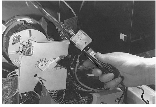
FIG. 17 Measure the high voltage at the CRT anode connection to determine
if the horizontal and high-voltage circuits are functioning.
High-voltage shutdown
Excessive high voltage can make the x-ray or shutdown circuits close down the horizontal circuits and shut down the chassis. This prevents excess radiation from the picture tube and prevents damage to other components within the TV chassis. Defective shutdown circuits can cause premature high-voltage shutdown.
Monitor the high voltage with a high-voltage probe or meter at the CRT anode button (Fig. 17). Connect a dc meter to the horizontal fuse or flyback primary winding to check the voltage applied to the HOT. Slowly raise the variable isolation trans former line voltage while watching the high-voltage meter. Notice the voltage when the chassis shuts down, and determine if the high voltage is excessive before reaching the 120-V ac power line voltage; also note the high-voltage measurement.
Slowly raise the variable transformer to just under the high-voltage reading that shut down the chassis. Notice if the low-voltage source is higher than normal. If so, check the low-voltage regulator circuits. When the high voltage is high compared with the line and dc voltages, suspect a defective hold-down or safety capacitor or horizontal output transformer. If the chassis shuts down before reaching the normal high voltage, suspect a defective high-voltage shutdown circuit.
Disconnect the high-voltage shutdown circuit by removing the diode or resistor terminal from the PC board wiring. The high-voltage shutdown circuit takes a pulse from a winding of the flyback and rectifies it with the voltage regulator diode to the transistor or SCR circuit that shuts down the driver or horizontal oscillator stage. Some chassis have a shutdown circuit that is fed back to the countdown oscillator IC and driver circuits, shutting down the horizontal circuits.
If the high voltage is normal and does not shut down with the shutdown circuits disconnected from the flyback circuits, repair the shutdown circuits. Always replace any terminals that were removed after the chassis has been repaired.
TV chassis shutdown
The TV chassis may shut down when there is a defective part in the horizontal or vertical circuits or the low-voltage power supply. Most shutdown problems occur in these stages. Chassis shutdown can be caused by poor terminal connections, defective transistors and ICs, poorly soldered terminals, or cracked PC board wiring. Monitor the horizontal circuits at the countdown sweep circuits, check the low voltage at the HOT, scope waveforms at the base of the output transistor, and check the high voltage at the anode of the picture tube. Notice which circuit begins to malfunction when the chassis shuts down.
A defective 10- uF, 160-V capacitor can cause intermediate shutdown. A capacitance of 100 uF at 160 V can shut the chassis off after 15 minutes. Check all electrolytics with the ESR meter. The defective flyback can start the chassis up momentarily and then shut it off. A defective relay can intermittently shut the chassis off. A defective HOT can make the chassis shut off.
The STR30135 line voltage regulator would operate 10 to 15 minutes and then shut off, although the relay stayed on. Badly soldered joints on the line voltage regulator IC or transistor may shut the set off intermittently.
Suspect a 6.8-V zener diode when the TV comes on but shuts off immediately.
Badly soldered joints on small resistors can cause the TV to immediately shut off. The TV shuts off with an extremely bright raster, and when the screen control is turned down, the set may stay on, and this is caused by a low 22-ohm resistor on the CRT neck board. Resolder all joints on the driver transformer when the TV intermittently shuts off. A bad driver transistor shuts the set off after 5 minutes of operation.
A defective yoke will let the relay click, and the set tries to start up and shuts off at once. A badly soldered joint on the relay cuts the TV off at once. When the chassis appears dead when the relay clicks on and then off, this is caused by a defective HOT. When the dead chassis relay clicks on and then off, this is caused by a defective yoke assembly.
In an RCA CTC197 chassis, the set came on very briefly and then shut off; this was caused by the HOT (2SC5148), CR4115 (33-V) zener diode, R14126 (30 kilohm), R14305 (3.6 kilohm), and R13159 (15 kilohm).
High-voltage problems
Besides high-voltage arc-over, the IHVT flyback can have arcing diodes or capacitors within the molded component. The high voltage may not come up or may cause shut down with leaky voltage diodes in the secondary winding of the flyback. Overloaded circuits in these voltage sources can be caused by leaky components within the audio, video, and vertical circuits.
Improper screen grid voltage can be caused by a burned isolation resistor or leaky diode in the derived secondary circuits. The symptoms include brightness that cannot be turned down, excessive brightness, or chassis shutdown. Disconnect each diode from the secondary circuits to determine what section is overloading the horizontal output transformer. Check each circuit after removing each diode.
Replace a bad transistor regulator when the TV has very low high voltage (19 kV).
An open safety capacitor can let the high voltage go very high, and the TV shuts down at once. Check for defective electrolytics (100 to 200 V) when there is no horizontal sync, and the high voltage is raised to 33.5 kV. Suspect 4.4- to 22- uF capacitors when the set comes on and the high voltage goes above 32 kV and shuts down the chassis.
Check a 100- uF, 25-V electrolytic with the ESR meter when the TV comes on with the high voltage around 10 kV and then shuts off.
Check for defective silicon diodes in the power supply regulator circuits when the picture is shrunk on both sides and the high voltage is down to only 18 kV. After re placing the HOT and the TV comes on with only 10 kV of high voltage, replace the fly back. You may have to replace the defective yoke after replacing the HOT when the high voltage is only 10 kV. A badly soldered joint on the horizontal linearity coil can cause the high voltage to go down to 10.5 kV. Replace IC400 (optoisolator) in a Magnavox 25G1-02 chassis with no raster, no audio, and a high-voltage reading of 15 kV.

FIG. 18 Replace CR4402 and C4402 for curved sides in the picture on an RCA
F31700GG TV.
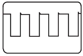
FIG. 19 An output waveform taken from the horizontal deflection IC.
The bow and arrow
When the picture is bowed inward on each side, suspect a defective pincushion circuit. In large TV screens (27 in and up), a pincushion correction circuit corrects distortion on the face of the large picture tube. You may have to look closely at a door frame or building in the picture to really notice the bowing. The pincushion circuits are defective if the outside edges of the TV raster bow. Improper adjustment of the pincushion coils may bow the picture at the top and bottom of the raster.
Check all large 1000- uF, 10-V electrolytics when the picture is curved in on both sides (pincushion problem). If the picture is pulled in on both sides like an hourglass, suspect 470- uF, 200-V electrolytic capacitors. Suspect defective bypass capacitors in the pincushion circuits for bowed pictures on both sides. Check the small resistors on the convergence board for bowed-in sides and a screen that goes out of convergence.
Check the silicon diodes in the pincushion circuits when the raster is bowed on both sides and the picture goes out of convergence.
Look for open traces in the pincushion circuits for a picture that is bowed on both sides. Use the ESR meter to find breaks in the traces and PC wiring. Check Q1 and Q2 in the pincushion circuits for a curved picture on both sides with the diode tester of the DMM.
In an RCA F31700GG TV, the horizontal pincushion problem resulted in a picture that looked like an hourglass. Besides curved sides, there was static and noise in the picture. C4402 and CR4402 were replaced and solved the pincushion problem. C4402 had a changed value (Fig. 18).
Critical horizontal waveforms
The most important waveform in the horizontal circuits is the square wave at the horizontal deflection IC (Fig. 19). Next, check the horizontal waveform on the driver transistor (Fig. 20). A waveform taken at the base of the HOT will indicate that the horizontal circuits are normal at this point (Fig. 21). Take a quick wave form with the scope probe alongside of the flyback to see if the horizontal circuits are functioning (Fig. 22).
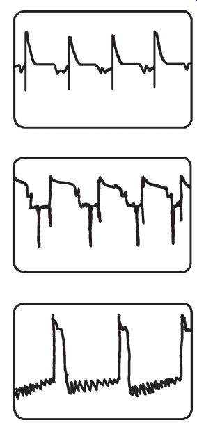
FIG. 20 The horizontal driver transistor waveform indicating that the deflection
and driver transistors are okay.
FIG. 21 The normal waveform found on the base of a horizontal output transistor (HOT).
FIG. 22 The waveform taken with the scope probe held alongside the flyback indicating that the horizontal circuits are functioning.
Vertical problems
Locate the vertical output IC on the chassis, which is tied into one of the yoke's vertical windings (Fig. 23). In early chassis, two vertical output transistors are found mounted on their own heat sinks. Most trouble found in vertical circuits results from a defective vertical deflection IC, bad silicon diodes, or defective electrolytic capacitors.
Improper or no voltage from the low-voltage power supply or flyback can cause insufficient height or a horizontal white line.
Vertical fold-over and rolling problems go hand in hand, whereas retrace lines at the top of the screen can be caused by bad resistors, electrolytics, and vertical output ICs or transistors. Dried-up filter capacitors can produce vertical crawling, whereas intermittent vertical sweep can occur at just about any place in the vertical circuits.
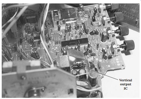
FIG. 23 Locate the vertical output IC on a metal heat sink.
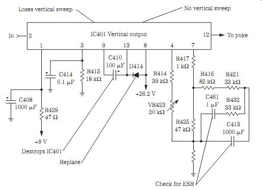
FIG. 24 Check the critical components when the vertical section is acting
up.
ONLY A HORIZONTAL WHITE LINE
No vertical sweep can be indicated by a horizontal white line across the CRT. Turn the screen control up so that you can see a no-raster or vertical sweep. Always try to use the correct schematic to quickly locate a defective part. Although vertical circuits are easy to service compared with others, try to locate a schematic of another product by the same manufacturer or a similar circuit. Vertical circuits have not changed much over the years, except that now all the vertical circuits may be found in one large IC.
No vertical sweep can result from a bad deflection IC, badly soldered joints on the defection IC, open traces, low-ohm resistors, or an open yoke winding (Fig. 24).
Resolder all pin terminals on the deflection and output ICs. Check the yoke return electrolytic with the ESR meter when there is no vertical sweep. A defective zener diode in the vertical or voltage regulator or the low-voltage power supply or voltage source can cause a no-sweep symptom.
Do not overlook a defective return electrolytic or open resistor in the leg of the deflection yoke circuits. Check all electrolytics in the vertical circuits for no vertical sweep. Suspect no voltage source when there is an open 1.5-ohm resistor at pin 5 of the flyback. Solder all pins on the flyback that can produce a horizontal white line. Replace IC301 (LA7837) when it is shorted between ground and pin 12, and also replace the FR301 (2-ohm, 1-W) fusible resistor in a Goldstar GCT-1904 TV for no vertical sweep.
NOT HIGH ENOUGH
Insufficient height or only 2 to 3 in of height can be caused by a defective transistor or vertical output IC. Poorly soldered joints on the vertical IC can cause poor height.
Defective electrolytic capacitors also can cause poor height. Check all electrolytics (33 to 100 uF) on the vertical voltage source for insufficient height. Only 1 in of vertical sweep can result from a defective 560- uF, 25-V electrolytic. Check all electrolytics with the ESR meter in the vertical circuits and on the height control.
Sometimes the defective electrolytic (100 uF) produces only 1 to 2 in of vertical sweep.
Check all diodes in the vertical output circuits for improper vertical sweep. Do not overlook a change in resistance in the pincushion circuits when there are vertical problems. Only 2 inches in the center of the screen can be caused by a badly soldered joint or terminal of the vertical output IC (Fig. 25). Replace a bad vertical size control when there is only 2 in of vertical sweep.
A Sylvania 25N1 chassis could not be turned off with no vertical sweep, and this was caused by IC550 (LA7831), R445 (1 ohm), C558 (100 uF), and D551; these parts have a tendency to cause IC550 to become leaky.

FIG. 25 Poorly soldered vertical IC connections and bad electrolytics and
silicon diodes can cause various sweep problems.
ONLY A VERTICAL WHITE LINE
Usually the no-sweep problem occurs in the vertical output, vertical yoke winding, or vertical oscillator circuits. A waveform test at the vertical countdown IC or oscillator will indicate if the stage is working. Check the vertical input circuits when there is no vertical waveform.
Check the output transistors with in-circuit beta or voltage measurements. measure the voltage supply terminal if the output IC is suspected. In vertical stage transistors, especially directly coupled circuits, scope waveforms may not be useful. With IC countdown and output circuits, the vertical waveforms can be checked at the vertical output terminal on the countdown IC, the input terminal of the vertical output IC, or the output terminal of the vertical output IC.
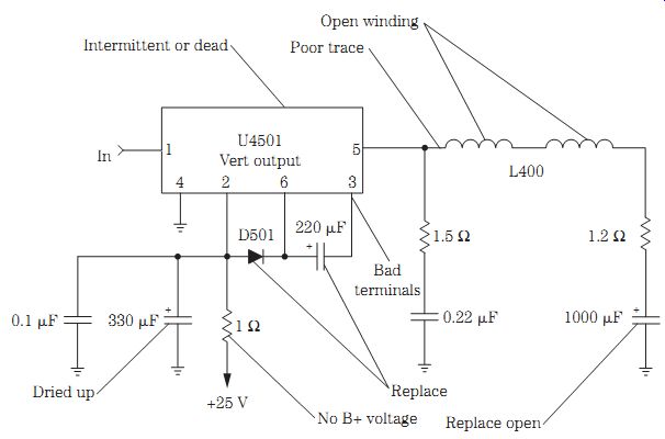
FIG. 26 The most critical components within vertical output circuits that
cause various sweep problems.
INTERMITTENT VERTICAL SYMPTOMS
Intermittent vertical problems are difficult to locate because they can result from many TV circuits. Monitor the vertical circuit output with the scope and voltage with the DMM at the vertical voltage source. Try to isolate the intermittent within the vertical deflection or output circuits. Attach a scope probe to the vertical oscillator or countdown circuits. If the countdown or oscillator circuits are normal, suspect the output transistors or ICs. Scope the input and output of the vertical output IC to determine if the output IC is intermittent. Take a waveform on the electrolytic coupling capacitor from the vertical circuits to the yoke winding.
The yoke coupling capacitor may be open, producing a horizontal white line and in sufficient sweep, or it may be dried up, producing a bunching of white lines at the top of the raster. Always check the vertical return resistor (under 50 ohms) or capacitor found at the ground end of the yoke winding.
Intermittent and partial loss of vertical sweep can be caused by a silicon diode or electrolytic in the vertical output circuits. Badly soldered joints on the vertical output IC can cause intermittent vertical sweep. Resolder all output IC pin terminals (Fig. 26).
Check for badly soldered joints on both vertical output transistors. Intermittent loss of vertical sweep can result from a bad yoke connection or socket or a break in the yoke winding. An intermittent diode in the vertical output circuits can cause an intermittent vertical raster. Do not overlook bad foil or traces in the vertical circuits for intermittent vertical sweep. Intermittent loss of vertical sweep in about 5 minutes on a Hitachi CMT-2090 TV was caused by IC681 (UPC1378); one also should check the vertical coupling capacitor (C685).
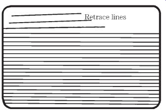
FIG. 27 Bright retrace lines at the top of the picture result from a defective
electrolytic or diode, a bad yoke or IC output, poorly soldered connections,
or defective small 1- to 2.2-ohm resistors.
CRAWLING UP THE WALL
When lines bunch together and slowly crawl up the raster, suspect the large filter capacitors or poor low-voltage regulator circuits. The raster may have dark horizontal lines along with the crawling lines. Shunt each filter capacitor with one of the same capacity or higher and with the same or higher working voltage. Shut down the chassis, and clip the capacitors across the suspected ones so as not to damage solid-state devices. Shunt the vertical output coupling capacitor when line bunching occurs.
If more than one capacitor is found inside a component and only one section is causing the problem, replace the whole capacitor component. Look for the tallest electrolytic capacitor on the chassis. Sometimes a large capacitor (650 uF or more) may be mounted on the TV PC board.
BRIGHT LINES AT THE TOP
Within the vertical transistor output circuits, retrace lines may be caused by the two output transistors, bias resistors, and diodes. Retrace lines in the power vertical IC output can result from a defective vertical IC, electrolytic capacitor, or drive from the deflective IC. Do not overlook a defective filter capacitor within the output IC voltage source.
Bright horizontal lines at the top of the raster or picture and retrace lines that may be bunched up closely together or spread apart occur at the top of the picture. Insufficient vertical sweep and retrace lines at the top can result from a bad yoke assembly. A defective vertical output IC can cause lines at the top of the picture and some vertical foldover. Bright retrace lines with video barely visible can be caused by a defective video buffer transistor.
Check the 100- uF, 50-V electrolytic in vertical circuits for lines at the top of the picture. A bright picture with retrace lines can be produced by a defective 10- uF, 160-V electrolytic capacitor (Fig. 27). Check all electrolytics in the vertical circuits with the ESR meter.
A defective vertical output transistor can cause lines at the top of the picture and some vertical foldover. Check for open small resistors from 1 to 2.2 ohms on the neck of the picture tube board. When the TV comes on with retrace lines, TV shutdown can be caused by excessive dust within the CRT spark gaps. A bright green picture with re trace lines can be caused by a shorted picture tube. Check the video amp terminals when there is a very bright screen with retrace lines at the top.
A Magnavox 25B8 chassis would come on with an extremely bright raster and re trace lines at the top and then shut off. If the screen control was turned down, this allowed the set to stay on with a bright raster. Replace the R58 (22-ohm, 1/4-W) resistor on the neck of the CRT board to fix this retrace-line symptom.
Replace a defective luminance driver transistor for retrace lines. Retrace lines at the top of the screen can result from a bad vertical output IC. Check all transistors on the CRT neck board for loss of color and retrace lines in the picture. Open traces or PC wiring on the CRT board can cause a bright picture and retrace lines. An open secondary winding of the flyback between pins 8 and 10 can cause a washed-out picture with retrace lines.
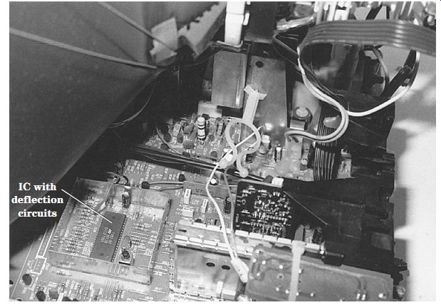
FIG. 28 The location of a large IC that has luma, chroma, picture, sync, and
horizontal and vertical deflection circuits.
NO VERTICAL DEFLECTION SYMPTOMS
The countdown or vertical deflection IC circuits are inside one large IC component along with the horizontal deflection, color, luma, sync, and picture circuits. Simply locate one of the largest ICs on the TV chassis and take critical waveforms and voltage tests (Fig. 28). Locate the vertical deflection IC that goes directly to the vertical output IC. Look at the part numbers on the IC, and look them up in the semiconductor manual. A scope waveform at the vertical output terminal indicates a drive pulse. Suspect a defective IC or improper supply voltage if no drive waveform is found.
Loss of or weak vertical sweep can be caused by a defective vertical deflection IC.
A leaky vertical deflection IC can cause no vertical sweep. Resolder all IC terminals for intermittent vertical sweep. Simply advance the screen control until you see a raster or a white line that indicates a bad vertical deflection IC. Make sure that the correct sup ply voltage is applied to the deflection IC terminals before removal.
FOLDOVER AT THE TOP
Most vertical foldover problems are caused in the vertical output IC or pincushion circuits. Vertical foldover at the top 3 in of the raster can be caused by defective 100- uF, 35-V electrolytics. Check the small 1- uF, 35-V electrolytics on the pins of the vertical output IC for only 6 in of vertical sweep and foldover at the top of the raster. Suspect a bad silicon diode when incomplete vertical sweep and foldover occur. Foldover at the top of the screen can result from a defective vertical output IC. Replace the vertical output IC when there is foldover at the top of a rolling picture (Fig. 29).
FIG. 29 Vertical foldover in an RCA CTC177 chassis was caused by a defective 220- uF electrolytic on pin 6 of the vertical output IC (U4501).
A defective vertical output transistor can cause insufficient vertical sweep at the bottom of the screen, and vertical foldover at the top can be caused by defective electrolytics in the vertical circuits. Test all electrolytics in the vertical circuits with the ESR meter. Poor voltage regulation and a slight vertical foldover can be caused by an STR30130 voltage regulator. Suspect a defective EEPROM IC for a dead chassis that does not turn on with vertical sweep pull-up from the bottom of the raster. Suspect a 1000- uF coupling electrolytic for foldover problems.
Poor vertical linearity can be caused by the vertical output IC. Replace the defective size control when there is a severely stretched picture. For severely stretched vertical sweep, check for an increase or decrease in megaohm resistors in the vertical circuits.
Check all electrolytic capacitors within the vertical circuits with the ESR meter.
When the top of the picture is stretched, this can be caused by a bad 2200- uF, 25-V electrolytic on the main board. Poor vertical linearity on the top half of the picture and stretched over the remainder of the picture was caused by defective 2.2- to 22- uF electrolytic capacitors. Poor linearity on the top half of the picture and incomplete vertical sweep at the bottom was caused by a 470- uF, 25-V electrolytic. Incomplete sweep at the bottom of the picture with poor linearity was caused by a 1- uF, 50-V electrolytic.
In a GE 25GT510 model, a white horizontal line was found in the center of the screen, and there was a stretched vertical linearity at the top half; this was caused by defective CR4501 (Fig. 30).

FIG. 30 Defective CR4501 in a GE 25GT510 TV resulted in a white horizontal
line and a stretched vertical linearity at the top half of the screen.
ROLLING UP AND DOWN
Improper vertical sync applied to the oscillator or countdown IC can cause vertical rolling. The vertical raster will not stay in one place. Sometimes vertical rolling and foldover problems are caused by the same defective part. Scope the vertical sync applied to the vertical circuits. A change in the resistance of the base or emitter circuits can cause improper vertical lock. Remove one end of the resistor or diode for accurate measurement.
Improper dc supply voltage to the vertical circuits can produce vertical rolling.
Small 1-uF electrolytics can cause a vertically rolling picture. Partial loss of vertical sweep, plus severe vertical rolling, can be caused by a change of resistance in the vertical circuits. A vertical bounce and roll may be caused by a defective silicon diode in the vertical circuits. Replace the vertical output IC when there is a flipping vertical roll and foldover at the top on some channels. Check large 470-uF electrolytics when the vertical will not lock in until after several minutes of operation.
Suspect an STR30130 voltage regulator when there is a slight weave in the picture with stretch height. Large 1000- uF, 25-V electrolytics can cause a loss of 1/4 in vertical sweep at the bottom of the picture and severe jumping after 15 minutes. Vertical jitter and incomplete vertical sweep at the bottom of the picture can be caused by a 470- uF, 250-V electrolytic. Tearing in the picture and incomplete sweep at the top can be caused by a 220- uF, 25-V electrolytic off the 16-V line from pin 7 of the flyback.
Replace the vertical IC for severe jitter. A vertical jitter when the channels are changed and especially on strong signals can be caused by a defective STR30130 voltage regulator. Replace IC421 (LA7837) and C426 (100 uF, 35 V) when the vertical output IC fails and when there is vertical jitter with a loss of vertical sweep in a JVC AV-20CM4 TV.
VERTICAL COMPONENT LOCATION
In early TV chassis, vertical output transistors were located on metal heat sinks. To day you may find one IC that contains all the vertical output circuits. Look at the numbers and letters on top of the IC for correct identification. This vertical IC also will be mounted on a small heat sink. Also check these numbers and letters out in a universal semiconductor replacement manual. For instance, an LA7835 IC is a vertical output IC that can be replaced with a universal NTE18555 IC. The semiconductor manual will show the input, output, and supply voltage terminals of the vertical output IC.

FIG. 31 The correct waveform found at the output terminal of the deflection
IC.
FIG. 32 The vertical output IC waveform that is fed to the yoke windings

FIG. 33 A vertical feedback sawtooth wave form indicating that the vertical
circuits are functioning.
IMPORTANT VERTICAL WAVEFORMS
The waveform found at the output of the vertical deflection IC are like inverted pipes in the latest TVs (Fig. 31). This waveform is fed into the input of the vertical output IC. The vertical output waveform from the vertical output IC represents a kind of a sawtooth (Fig. 32). A feedback waveform is a regular sawtooth waveform indicating that the vertical circuits are functioning (Fig. 33).
System control
A typical system control IC may be controlled by one large IC. It is possible that only one control system function may be bad, whereas the rest of the functions are normal. Suspect the system control IC when several functions are not operating. Infrared circuits are fed into the system control IC to operate many system control circuits. Key input push buttons control the power, volume, display, channel up and down, and reset functions.
The contrast, tint, color, brightness, sharpness, on-screen display (OSD), gain, and standby circuits are controlled by the system control IC. The vertical, automatic fine tuning (AFT), tuning, horizontal, vertical, sync, hold, and reset circuits are part of the circuits that the system IC actually controls (Fig. 34).
Go directly to the system control IC when any one of these circuits cannot be operated. Check the supply voltage terminal pin for the correct voltage (5 V). A dirty switch contact or diode in the switch key input circuits can cause failure of a particular function. Scope the crystal for in and out waveforms for clock data. Do not forget that many of these control features have separate transistors that help operate the various circuits after receiving the right command from the large system control IC.
Check the system, interface, and control system when one or more control functions are not operating. Check to see if both the remote and keyboard functions are working. Suspect the infrared circuits when the TV can be operated with the keyboard functions. When one function does not operate, check the signal from the control IC to a corresponding transistor or IC. A bad microprocessor or control IC may cause problems with auto programming, no screen display, no up and down volume, or a snowy condition. Check for a defective microprocessor with intermittent loss of functions such as volume up and down or channels up and down. Suspect a bad control IC when a display such as tint or closed captions is shifted to the left.
A defective control micon IC may cause vertical jitter and horizontal white lines in the picture. After warmup, a defective micon IC may lock up and not let the TV be turned off. Replace the control IC when, after warmup, the volume and channel up and down controls lock up. Replace the micon IC when there is a loss of video and green horizontal lines appear on the screen. The defective control IC may result in a dead chassis and no relay click. Replace the micon control IC when the relay begins to chatter.
After 10 minutes, the defective micon IC may cause the on-screen display to show jumbled characters. A defective control IC may intermittently let the volume go real loud, become intermittent, and lock up. The control micon IC may cause a dead chassis. A defective EEPROM that works in the control circuits can cause many different control function problems. A leaky control micon may cause no picture. Chassis shut down can result from a bad control micon IC. Do not overlook defective components tied to the control IC that can cause many different problems.

FIG. 34 The many circuits that the system control processor controls in the
present-day TV.
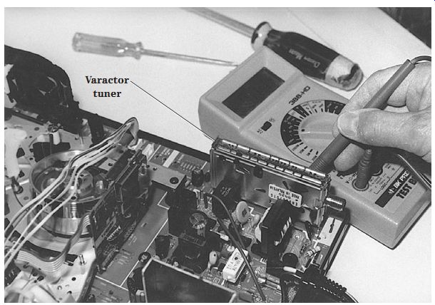
FIG. 35 The varactor tuner is usually mounted on its side and operates with
no moving parts.
Tuner on the side
The old wafer tuner was found in early TVs, whereas today the varactor tuner may be located separately or in a shielded control case. The old tuner switching contacts would become dirty and had to be cleaned with a cleaning fluid. The varactor tuner has no moving parts and is tuned electronically. Today, the varactor tuner is con trolled by a system control IC or a microprocessor.
The varactor tuner can be mounted on edge right on the PC board with the bottom contacts soldered into the PC board wiring. Today, some of the tuner's components are found mounted directly on the PC board under a metal shield (Fig. 35). Tuners under warranty should be removed and returned to the manufacturer's service center. Older tuners out of warranty can be sent to tuner repair centers.
A defective tuner can cause a snowy, weak, dim, intermittent, or flashing picture; erratic or drifting channels; or a white raster. Check for a defective tuner by plugging a tuner subber into the IF socket or connection. Voltage measurements, tuner subber injection, tuner substitution, and correct automatic gain control (AGC) voltage can help you discover a defective tuner. A defective tuner module should be removed and sent in for repair.
The RCA tuner in a CTC177 chassis is mounted on the PC board; resoldering the tuner grounds can solve a lot of different TV problems. Improper supply voltage to the mixer/OSC IC (U7301) can cause a snowy condition. An open R7401 (191-kilohm) resistor to the UHF/OSC at pin 14 can cause a snowy picture. A defective U7301 IC can cause a snowy picture on the VHF band. A badly soldered joint on pin 14 of the tuner control IC (U7401) can cause a snowy picture. A defective VHF RF amp (Q7102) is noted for a snowy picture in this tuner.
In the same tuner, open resistor R717 (100 kilohm) feeding voltage to G1 of Q7102 caused no tuner operation. Likewise, a defective VHF RF amp (Q7102) resulted in no tuner operation. No reception on channels 2 through 13 can be caused by a defective U7301 IC (CXA1594L). A defective U7301 can cause snow on all channels, whereas the auto programming band jumps from cable to air mode. After the auto programming stops, the RCA CTC177 chassis is stuck on one channel.
Resolder all ground terminals under the tuner shield for intermittent reception on channels 7 to 13 and the UHF stations. Poor tuner ground terminals can cause intermittent and partial loss of vertical sweep. Horizontal lines flashing across the entire screen can result from shielded ground terminals in the tuner. Resolder the ground terminals for intermittent snow on channels 2 through 6. U7301 can cause snow on all tuner channels.
A very dark picture plus intermittent snow can result from ground terminals under the tuner shield. Replace U7401 when the channel display changes but the channels do not change; the picture may be snowy. The CTC177 chassis may be dead and then have a partial loss of vertical sweep when there are poor tuner grounds. Resolder each terminal on U7100 of the microprocessor for intermittent total loss of tuner action resulting in only snow and no audio.
Check for a leaky channel down switch (SW3420) when channels change by themselves. Replace Y7401, a 4-MHz crystal, for no tuner action. Intermittent display would show on the screen when there is a leaky menu button (SW3430).
No raster or a bright raster Check the high voltage with the screen control turned up high when there is no raster. Suspect problems within the video circuits when there is normal high voltage or a defective picture tube. Sometimes when the screen is black and with the screen control advanced, you can see if the TV has video or vertical or horizontal problems on the screen. Service the high-voltage circuits if there is no raster or high voltage is seen. No raster can be caused by no heater or filament in the CRT.
A defective picture tube can cause many problems, such as poor brightness, missing colors, intermittent picture, poor focus, a single-colored raster, arcing in the gun assembly, retrace lines in the picture, negative picture, chassis shutdown, no heater or filament lit, and no raster, to name a few (Fig. 36). An open filament or heater can cause a no-picture or no-raster symptom. A defective CRT can have an extremely bright screen. Loose particles off the cathode element can lodge between the grids and cause an intermittent black-and-white picture. Simply tap the end of the CRT gun assembly and notice if the picture begins to flash off and on.
With a leaky picture tube, after turn-on, the raster dims and then gets extremely bright. A dim picture with no green in the raster can result from a bad green gun assembly. A heater-to-cathode short can cause the raster to change color or result in no raster at all. Replace the picture tube if there is severe arcing in the neck of the CRT.
Excessive brightness with retrace lines and vertical collapse to a thin line can be caused by a bad coil on the neck board of the picture tube. Rejuvenate the picture tube when there is a very bright green screen. Check for a resistance change on the resistors on the CRT neck board for an excessively bright picture with retrace lines. Excessive dust inside the CRT spark gaps within the picture tube socket can cause a very bright raster and then chassis shutdown. A defective video amp, luminance buffer, or reference transistor can cause a bright picture with retrace lines.
Check the small 1- to 10-uF electrolytics on the neck of the CRT board when there is a very bright screen with retrace lines. Check for badly soldered joints and traces on the neck board of the picture tube when there is excessive brightness and retrace lines.
Replace Q5106 on the neck of the picture tube board in a Zenith SS2014W TV for extreme brightness with retrace lines.
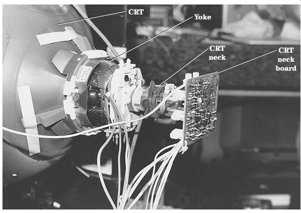
FIG. 36 There are many CRT components mounted on the neck of the picture tube
socket board.
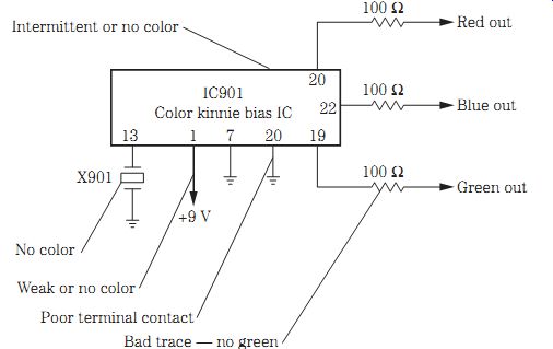
FIG. 37 Check the following components for no, intermittent, or weak color
in a TV chassis.
Color symptoms
Today, the color circuits are found in one large IC or microprocessor. With a normal picture and good sound, suspect the color circuits when there is poor or no color in the picture. Locate the chroma-luminance IC on the chassis. This IC contains the IF video, chroma, and deflection circuits. The chroma IC may be located on a separate video luminance-color PC board (Fig. 37).
Scope the color IC for missing waveforms when there is no color. Check the color oscillator waveform (3.58 MHz) taken from the crystal pin on the IC. Check the terminals for a missing horizontal pulse from the flyback circuits. Check the three color output waveforms that feed the color output transistors on the CRT board. Suspect a defective color, picture, luma, or deflection IC for no color.
No color until the TV is on for an hour or so can result from a defective color crystal. A badly soldered joint on the color crystal can cause intermittent color. Distorted color may be caused by a degaussing problem. Weak color can be caused by improper supply voltage, a leaky IC, leaky diodes, and open coil windings in the color circuits. In a GE 19GT313C TV, no color was caused by a defective U1001 (215542).
Look for open coils and poor component terminal connections. Check for leaky capacitors to ground. Intermittent color can be caused by leaky capacitors in the color killer circuits. Take a resistance test from each terminal pin to the chassis ground.
Green with envy
Check the color output transistors when one color is missing, and test the guns in the picture tube. Loss of one or more colors can be caused by color, sync, luma, picture, and deflection ICs. A leaky gun assembly in the picture tube can cause an all-red screen. A blue screen with retrace lines can be caused by a bad blue output transistor and poorly soldered joints at the collector resistor. A yellow tint with no blue can be caused by badly soldered joints in the blue output transistor on the CRT neck board.
Check all 33- to 100- uF, 35-V electrolytics that tie into terminals on the color IC when colors fade out. Measure all resistors on the neck of the CRT board for correct resistance when there is a greenish raster and no video. Check all diodes on the CRT neck board when there is red, green, or blue screen with retrace lines, some video visible, and normal sound. A bad line voltage regulator (STR30130) can cause the raster to shrink on both sides, as well as vertical foldover and no color, in an NEC CT-2750S TV.
Weak or intermittent color problems can occur in the color output amps. Locate the color amps on the CRT socket board. A defective green output transistor can result in a green raster, and a defective red output transistor can cause a red screen. Check the voltages on each collector terminal. Test each transistor in-circuit. Universal transistors can be used in the color output circuits.
Surface-mounted components
Besides being used in camcorders and CD players, surface-mounted devices (SMDs) are now found in TV chassis and varactor tuners. Surface-mounted transistors have three end connections, whereas resistors and capacitors have only two soldered end connections.
Surface-mounted ICs or processors may have gullwing terminals. Usually a white dot or number indicates the terminal 1. Look up the part numbers stamped on the bodies of ICs and processors to locate the correct circuits.
Resistors and capacitors may have the correct values stamped right on the body.
You may find the part number corresponding with the schematic stamped alongside.
Surface-mounted transistors, capacitors, and resistors are very difficult to locate with out a schematic and magnifying glass.
Take voltage and resistance measurements on suspected SMD parts. Test each transistor in-circuit with a beta tester. Be very careful not to short the terminals during critical voltage measurements. Take care when removing and replacing SMD parts.
Always replace an SMD part when it tests normal after removing it from the PC board wiring. Don't try to use it again. Surface-mounted resistors and capacitors can be re placed with universal SMD parts. Replace transistors, ICs, and processors with exact replacements.
The "tough dog"
A "tough dog" problem may take hours, weeks, or several months to repair. Some times a repair may be called tough by one technician, whereas the next technician may locate it at once. "Tough dogs" seem to come all in one week or one month. Al ways set such a chassis aside after working on it for an hour or so. Time can be lost if you work half a day on it. Give it up for now, and tackle it the first thing in the morning when your mind is fresh.
Ask for help if you cannot locate the defective component after several attempts.
Go to the TV distributor or parts depot for help. If service personnel are not there, con tact the factory. A simple telephone call and 10 minutes of your time may save you several hours of frustration. Check with factory repair depots that repair boards or the entire chassis.
FIG. 38 The on-screen display (OSD) block diagram found in a CTC167 RCA chassis.
On-screen display
The OSD circuits are controlled by a micro control processor to a buffer amp transistor to a driver transistor that ties into the green amp output transistor and picture tube. The system control IC determines when to output the OSD signal. In an RCA CTC167CN chassis, the micro control (U3101) provides an OSD signal to the green buffer transistor (Q2903), to a green driver transistor (Q5004), and then to the collector terminal of the green output transistor Q5002 (Fig. 38).
Check the OSD circuits by scoping the input terminal of the OSD, luma, and OSD black-and-white signals. Scope the waveform on the OSD green buffer and OSD green driver transistors. Check for leaky diodes and transistors in the OSD circuits. A leaky diode and transistor will eliminate black around the characters. Replace the OSD green driver transistor when the display letters are black. Check for a defective EEPROM IC when there is no raster except for on-screen displays. OSD shifting to one side can be caused by a defective EEPROM. If there is no OSD, look for a leaky OSD transistor. No OSD in an RCA CTC145E chassis was the result of a leaky Q4501 transistor.
EEPROM problems
A defective EEPROM IC can cause many different problems in a TV. The EEPROM IC is found in only some TV chassis. A dead chassis can be caused by a defective EEPROM IC. No audio or video can be caused by a defective EEPROM IC. Replace the EEPROM IC when the tuner does not receive all the channels. Suspect the EEP ROM IC when numbers are off to the right side of the screen and some are not read able. Intermittent TV channels 7 through 13 can result from a defective EEPROM. A defective EEPROM will not let the TV be shut off. When there is no vertical sweep and, once on, the TV cannot be shut off, suspect a bad EEPROM IC (Fig. 39).
No screen display, a very dark screen, and only a faint video were caused by a defective EEPROM. A bad EEPROM can cause a loss of vertical and horizontal sync. Suspect a defective EEPROM when the picture goes snowy, there is no video, or there is vertical collapse. The chassis can be dead with an okay-fuse symptom caused by a bad EEPROM. No menu and no channel change from the TV or remote can be caused by a defective EEPROM IC. Check the EEPROM IC when the TV will not program above channel 13. No menu or function display can result from a bad EEPROM.
A bad EEPROM can cause an intermittently dead chassis. No audio, variable audio control, and normal screen display can be caused by a defective EEPROM IC. Replace the EEPROM IC when the raster turns red or green. No color visible with only information present was caused by a defective EEPROM IC. Suspect a defective EEPROM IC when the set comes on and goes into shutdown. When a Sharp 25VT-G200 TV was first turned on, there was no horizontal or vertical sync and no color or audio; this was caused by a bad EEPROM.

FIG. 39 The defective EEPROM in an RCA CTC187 chassis caused the TV to stay
on when it was turned off.
Audio problems
Sound problems within a TV chassis are about the same as those found in any audio amplifier. By signal tracing the audio signal with the external amp, you can locate the dead, weak, or intermittent stage. Today, TV audio systems have additional audio output jacks, fixed audio outputs, digital audio muting, and stereo sound circuits.
Low level and poor audio balance can be caused by an open or dried-up coupling capacitor. Check those 1- to 10- uF electrolytics with the ESR meter. No or distorted audio can result from a defective audio output IC. A badly soldered connection on the audio IC amp can cause intermittent sound in the left channel. Distorted audio can be caused by open filter capacitors on the voltage supply source fed to the audio circuits.
In an RCA CTC187 chassis, the stereo circuits begin with an IC1601 to the T-chip U1001. The left and right audio channels from U1001 are fed to right and left buffer, limiter, and mute transistors and then out hi-fi output jacks J1406 and J1405. For the TV speakers, the left and right outputs of U1001 are capacity-coupled (1- uF) electrolytics to the left and right input terminals of a dual audio output IC (U1901). Here the sound is amplified and capacity coupled (220 uF) to left and right 32-ohm permanent magnet (PM) speakers (Fig. 40). Refer to Section 3 for additional audio problems within TV chassis.
ACTUAL TV AUDIO PROBLEMS
Replace IC601 for no audio in a Goldstar CMT2035 TV. No sound in an Emerson EC134C TV was caused by open R354 (1.2-ohm, 2-W) resistor in the power supply.
Check the C320 (220- uF) electrolytic in a Sharp 35LM36 TV when there is no audio.
A bad switch transistor (Q1444) in a Sony KV20T520 TV caused no audio. Check Q603 for a leaky condition and replace an open R815 (560 ohms) off the 105-V source for no sound in a Samsung CT206S TV.
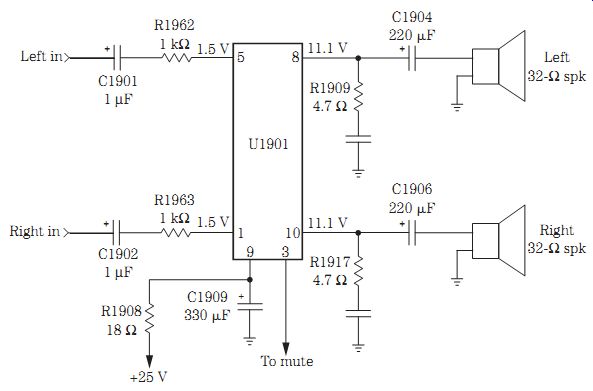
FIG. 40 No sound was noted in the left channel and very weak audio in the
right channel as a result of a leaky U1901 output IC in an RCA CTC187 chassis.
Leaky Q601 and Q602 caused distortion in a Samsung CT331 TV. Low audio and distortion in a Sanyo PC320 TV was caused by a defective C1870 (470 uF, 35 V) that kept destroying IC2850. Audio distortion in a Sharp 19MP17 TV was caused by an open R310 (100-kilohm) resistor. A defective IC201 (TA8642) caused distortion in a Goldstar CMT4842 model TV. Distorted sound in an RCA CTC140 chassis was caused by a leaky C1600 on pins 27 and 28 and a leaky IC1645 on pin terminal 12 of U1601. R301 had changed value off of IC101-4 and caused distortion at a low level of volume in a Magnavox CS2043R TV.
Check C4129 for audio buzzing in an RCA CTC175 chassis. Replace U3101 in an RCA CTC159 chassis for squealing audio. Replace the power audio output IC901 (STK563A) for no audio and a popping noise in a JVC C1950 TV. No audio, just hum was found in a Mitsubishi CS2062A TV and was caused by IC101-24 and the C113 (470- uF) capacitor. The volume would cut up and down with audio hum in an Emerson TC1372B TV and was caused by a defective IC401 (STR30130) voltage regulator in the power supply. A bad connection at the audio output 2SD401C in a Hitachi CT19A7 caused in intermittent audio and a cracking sound. Replace a bad regulator in a Sony KV1951 TV for garbled audio.
Replace Q1552 (ECG123) in a Phillips E1 chassis for intermittent sound. Check IC1001 in an 19NP58 Sharp TV for intermittent audio. Resolder all connections on IC201 for intermittent audio in an NEC CT2020A TV. Replace T207 for intermittent audio in a Sony KV1943R TV. Solder connections on Q351 and Q352 for intermittent and no sound in an Emerson EC134C TV. Replace IC601 for intermittent audio in a Goldstar TS3140M TV. Check for a bad speaker in an RCA CTC145 chassis with garbled and intermittent sound.
============