Every electronic product must have some type of power supply so that the unit will function. The electronic product operates from the power line or batteries. Portable radios, cassette and CD players, and car radios operate from batteries. Large boom-box cassette players, CD players, TVs, DVD players, and VCRs operate from the ac power line. Of course, there are some radios and CD and cassette players that operate from both the power line and batteries.
You may find a dead electronic unit if improper or no voltage is found at the power supply source. Remember, the power supply is one of the most important sections of any electronic device. Go directly to the largest electrolytic capacitor, and measure the voltage across its terminals. Always check the power supply source before checking any other component (Fig. 1).
An ac radio, clock radio, CD player, or cassette player may have a step-down ac adapter power supply with a half-wave, full-wave, or bridge-type rectifier. Larger electronic products that operate from the power line use a power transformer with full wave and bridge rectifiers. Early TV chassis contained a power transformer with full-wave circuits. Newer power line TVs have a bridge rectifier with a line voltage regulator. And the latest TVs and TV/VCR combos have transformers in a switch-mode power supply (SMPS) or a switching transformer circuit.
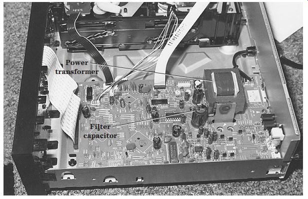
FIG. 1 Locate the power transformer to find the power supply circuits in a
Pioneer CD-5016 CD changer.
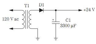
FIG. 2 A half-wave rectifier power sup ply circuit contains only one silicon
diode and filter capacitor.
Half full
Half-wave rectifier circuits were found in many of the early radios and some TV power supplies. The half-wave rectifier delivers a half-cycle of dc voltage for every half-cycle of applied ac voltage. The half-wave rectifier is found in the transformer less TV chassis, radios, and industrial applications. You will find very large electrolytic filter capacitors in the half-wave rectifier circuits. In early radios, a selenium rectifier or one large silicon diode was found (Fig. 2).
Full-wave rectifier circuits are located today in about every electronic unit, and they operate from the power line. A full-wave rectifier circuit contains two silicon diodes. Usually, the full-wave rectifier circuit will have two silicon diodes and a center tapped step-down transformer. Each diode rectifies an alternate half-cycle of the secondary voltage.
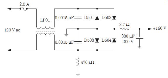
FIG. 4 The raw ac bridge power supply found in a TV chassis without a transformer.
The ripple in the dc voltage source is equal to twice the supply frequency, and the resulting hum is much easier to filter out in the full-wave circuits. You will find smaller filter capacitors in full-wave versus half-wave circuits (Fig. 3).
The damaged bridge
A bridge rectifier is found in many electronic products and contains four silicon diodes. Bridge rectifiers may be made up of separate diodes, two diodes in one part, or all four diodes in one rectifier component. Bridge rectifier circuits may be found in a TV transformer-less power supply or in a TV with a power transformer. The negative ends (anodes) of the two diodes are grounded, whereas the two positive ends (cathodes) provide a positive dc supply voltage.
Usually the power transformer is not centered tapped with a bridge circuit, such as that found in a full-wave circuit with only two silicon diodes. The cathode end of the diode is connected to the positive output supply voltage source. You can replace a defective bridge circuit with a single silicon diode when four diodes are found in one electronic component (Fig. 4).
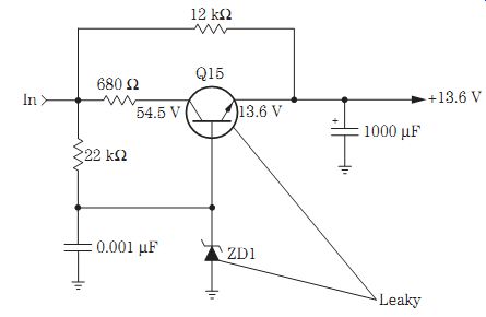
FIG. 5 Check the regulator transistor (Q15) and zener diode (ZD1) with the
diode tester of the digital multimeter (DMM).
Transistor regulators
Transistor and zener diode regulators are found in clock radios, cassette players, CD players, and auto radios. You also will find several transistor regulators within TV chassis, DVD players, and VCRs. Low-voltage transistor and zener diode regulators are found in AM/FM/MPX receivers, cassette decks, FM circuits, and audio preamp and output circuits. Usually the collector terminal of the regulator transistor is tied to the highest dc voltage, and the output regulated voltage is taken from the emitter terminal. A zener diode may be found within the transistor base terminal.
Suspect an open regulator transistor when there is no or very low output voltage.
An intermittent transistor can cause intermittent operation in transistor regulator circuits. Check for a leaky regulator transistor when the voltage output is lower than normal. Suspect a shorted or leaky diode within the base circuit of the transistor regulator when there is a shorted regulator transistor. Double-check the suspected transistor regulator, zener diode, and small-ohm resistors within transistor regulator circuits when there is no or low output voltage (Fig. 5).
Intermittent sound and a constant clicking of the protection relay in a Pioneer SX880 CD player was caused by a defective transistor regulator circuit in the power supply. At first, the regulator transistor was suspected of being intermittent. When the voltage probes were placed on the transistor regulator terminals, the CD player began to act up. Resoldering all connections on the regulator transistor terminals solved the intermittent CD player sound problem.
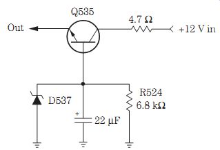
FIG. 6 The regulator transistor (Q535) found in an auto stereo cassette player.
IC voltage regulators
Integrated circuit (IC) voltage regulators are found in CD player, VCR, DVD player, and TV power supplies. The IC voltage regulator also may contain several transistors and zener diodes within the same voltage sources. Often the simple IC voltage regulator consists of an input and output terminal with a common ground terminal. A leaky or shorted IC regulator may have no or very low output voltage, whereas an open IC regulator shows very little voltage on the output terminal (Fig. 6).
The power line voltage regulator found in a TV chassis is fairly large and has several terminal connections. Double-check the power line voltage regulator when there is a damaged or shorted horizontal output transistor. A leaky or shorted flyback can destroy the line voltage regulator in a TV chassis.
Simply measure the output voltage at the input and output terminals. If no or very low output voltage is found, suspect a defective IC regulator or a leaky component causing the reduced output voltage. You will find several transistor and zener diode voltage regulators within the secondary voltage sources of the flyback or horizontal output transformer.
Critical voltage tests
An electronics technician should check the dc voltage across the largest filter capacitor first. If the voltage is low or too high, the defective component is within the power supply circuits. Check each voltage source with an accurate digital multimeter (DMM). Critical and very low voltages are found throughout electronic products. A dead power supply may have an open fuse with shorted or leaky silicon diodes, an open primary winding of the power transformer, or shorted or leaky voltage regulators. Leaky or shorted filter capacitors can blow the main power fuse. An open filter capacitor can cause a low-output dc voltage source and hum in the speakers.
A leaky transistor or IC regulator may have low output dc voltage. An open transistor or IC regulator has no output voltage. A leaky zener diode regulator can have lower output dc voltage. A transistor regulator becomes leaky or open, whereas the zener diode regulator becomes leaky and overheated with burned marks. You can easily spot a leaky or overheated zener diode in low-voltage sources. Take voltage measurements in and out of the suspected transistor or IC regulator to determine if it is open or leaky (Fig. 7).
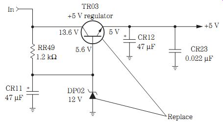
FIG. 7 Intermittent TV startup was caused by a defective TR03 and TR05 in
an RCA TX825TC power supply.
Storm damage
Critical storm damage or a power line outage can destroy components within an electronic product. An open fuse, shorted or leaky diodes, and power transformer damage can be caused by a heavy lightning hit. Sometimes only a fuse is blown with no power cord damage when a lightning strike occurs nearby. A heavy lightning strike can destroy many components in electronic products found in the home, as well as any unit connected to the power line.
A direct hit on a TV antenna and power line can cause extensive damage to the power cord, on/off switch, and low-voltage diodes and can result in open foil in the tuner and several black spots on the printed circuit (PC) board wiring of a TV chassis.
Besides damaged silicon diodes, large-wattage resistors may be blown open, and the line voltage IC regulator may be damaged. Sometimes a TV chassis can operate at 90 to 100 V ac with a damaged voltage regulator. Besides blown low-voltage diodes, check for damaged zener diode and transistor voltage regulators in the power supply. Low-ohm resistors within the standby circuits of a TV chassis can be damaged by lightning or other power line outage conditions.
A high-voltage power line surge can destroy the same components in the power supply as a lightning strike. Besides diodes and regulators, a power surge may destroy ICs and transistors in and out of power supply sources. You may find open traces of wiring caused by a power line surge. Blackened and blown-apart surge components within the power line circuits can be caused by high power line voltage surges. A clicking relay with a dead chassis may result from a high power line surge that can destroy the main filter capacitor (470 to 680 uF, 200 V) within a TV chassis. A power line surge on a Magnavox 27C9 chassis caused extensive damage to D404, D405, D407, F400, Q400, R422, R430, D425, and Q402.
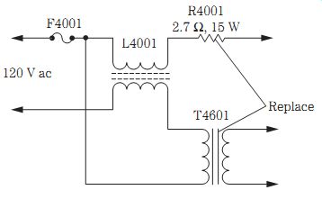
FIG. 8 The standby transformer (TR4601), resistor R4001 (2.7 ohms, 15 W),
SCR4101, and main filter capacitor (C4007) were replaced in an RCA CTC159
chassis as a result of storm damage.
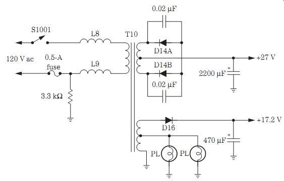
FIG. 9 The power supply circuits located in an AM/FM cassette player.
STORM DAMAGE, RCA CTC159
An RCA CTC159 chassis was dead and had several damaged components in its power supply circuits. No voltage was measured across the main filter capacitor (C4007). After replacing an open (2.7-ohm, 15-W) resistor (R4001), the chassis was still dead. All diodes were suspected, but they tested normal with the diode tester of the DMM. SCR4101 was tested and replaced. The CTC159 chassis still would not operate until the standby transformer (T4601) and the main filter capacitor (C4007) were replaced (Fig. 8).
Repairing radio power supply circuits
Most radio power supplies consist of batteries, ac power circuits, or ac adapters (Fig. 9). When the adapter is inserted, the batteries are disconnected from the circuit.
Likewise, in large battery and ac power supply circuits, the batteries are switched in and out of the circuit.
In some models, an external battery source can be plugged into the radio, disconnecting the batteries within the radio. The ac power supply is not in use when the batteries are switched into the circuit. Poor switch and dirty jack contacts can prevent the radio from operating. Check the switch contacts and plug with the low-ohm scale of a DMM. Clean the switch and jack contacts with cleaning fluid.
Check the batteries. Weak batteries can cause weak and noisy reception or slow tape motor movement. Poor battery contact can be caused by leaky batteries and corroded terminals.
CLOCK RADIO AC POWER SUPPLIES
Most clock radio power supply circuits consist of a simple full-wave rectifier and an electrolytic filter circuit. Often a step-down transformer reduces the line voltage from 10 to 25 V ac. You may find two silicon diodes or a bridge circuit in the full-wave circuit. A low-ohm resistor and main filter capacitor are found in the dc voltage out put circuits.
In larger models, diode and transistor/IC voltage regulators are found. If the radio is also battery operated (9 V), the highest supply voltage will be around 9 to 10.5 V. A 10.5-V source feeds the power IC and transistors, whereas a 6.1-V source is tied to the cassette preamp tape circuits. The lower voltage is tied to the AM/FM radio circuits.
Large table model radios with a light-emitting diode (LED) clock display have several secondary windings on the power transformer. High ac voltage (25 to 50 V) is rectified with two silicon diodes, and the resulting voltage is applied to the clock display.
Another ac winding ( 3 to 5 V ac) goes directly to the clock display. A bridge rectifier circuit attached to another winding provides dc voltage to the tape motor and audio circuits.
Check the clock radio power transformer circuits by checking the resistance across the ac line cord plug. The resistance measurement should show the resistance of the primary winding of the step-down transformer with the power switch on. Suspect an open primary winding or power switch when there is no reading. Usually, one or two sil icon diodes become leaky or shorted and place a load across the secondary winding.
Since the primary winding is wound with small wire, the winding opens up.
DEAD CLOCK TIMER CIRCUIT
In a General Electric 7-4665B clock radio, no time could be seen on the electronic tube display panel, and the radio was dead. No output voltage was found on voltage regulator Q103. No ac voltage was measured on the secondary winding of T101. The primary winding of T101 was found to have no resistance and thus was open (Fig. 10).
TROUBLESHOOTING CLOCK POWER SUPPLIES
Check the primary winding and ac plug with the low-ohm scale of a DMM (50 to 150 ohms) if a clock is found to be dead. Often, shorted diodes and leaky filter capacitors will open the primary winding of the transformer. The transformer produces voltage when plugged into the wall outlet. The dc voltage is switched to the radio or tape player.
Check the different voltage sources by measuring the voltage across the large filter capacitor. If a voltage is not found at this point, check each silicon diode in the circuit.
Measure the ac voltage across the different transformer wire leads. Check for dc voltage at the emitter terminal of the suspected voltage regulator.
In today's table, clock, and portable radios, only one power transformer is found.
The transformer can be mounted on or off the large PC board. A large filter capacitor is found close to the silicon diodes. Look for larger decoupling capacitors in lower-voltage sources (220 to 470 uF). You may find the power supply circuits close to the audio out put transistors.
Weak or no audio can be caused by leaky voltage regulator diodes and transistors.
Open regulator transistors and burned isolation resistors can result in no sound. Don't overlook a dried-up decoupling capacitor if there is weak or distorted audio.
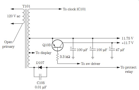
FIG. 10 An open primary winding in a clock radio power supply circuit resulted
in no radio reception.
REPAIRING THE AC ADAPTER
Check the low-voltage source of the ac adapter power supply at the metal plug. This voltage will measure a few volts higher than that marked on the adapter body. The ac adapter consists of a small power transformer, diodes, an electrolytic capacitor, a flat lead, and a male plug. If there is no voltage, measure the resistance across the male plug to determine if the primary winding is open or normal. Remove the adapter from the wall outlet when taking resistance measurements. Replace the en tire adapter if the transformer winding is open (Fig. 11).
Often the flat rubber cord will break at the male plug or where it enters the adapter case. Lightly pull on the cord at the male end. Cut off the male plug and install a new one if the wire stretches or appears broken where it enters the plastic plug.
To check the dc cord continuity, stick a safety pin where the cord enters the ac adapter and check the resistance or continuity on the low-ohm scale of a DMM. Like wise, check both sides of the wire from the adapter to the male plug in the same manner. If there is no continuity measurement at the male plug, stick another safety pin into the insulation in the same manner as the first pin. You can check each cord for possible breakage with this method. If a break in the cord is found, cut out the broken area, solder up the two broken ends, and tape over the damaged area.
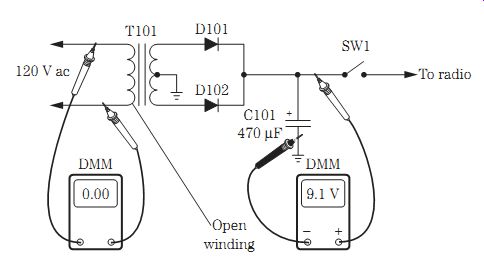
FIG. 11 Check the primary for an open winding with an ohmmeter and the output
voltage with a DMM in a dead adapter power supply.
HUM IN THE SPEAKERS
Go directly to the large filter capacitor or voltage regulator for a low or excessive hum in the audio. Pull the ac plug, and discharge the large filter capacitor (1000 to 3300 uF) with a test clip or screwdriver. Solder or tack in a good electrolytic capacitor of the same capacity or higher. Observe the correct polarity. If the hum disappears, replace the dried-up filter capacitor.
Hum can be caused by a leaky voltage regulator transistor or diode. Defective de coupling capacitors in the voltage-dropping circuits can cause a low hum in the sound.
Check both the regulator transistors and the diodes in the circuit for leakage. Shunt a suspected decoupling electrolytic capacitor with one of a known value.
Motor boating or a put-put noise in the speakers can result from defective filter capacitors and diodes. A bad filter capacitor can cause a high-pitched squealing noise. A hissing sound from the power supply can be caused by small electrolytic capacitors (22 to 47 uF, 25 to 63 V). An open or dried-up electrolytic filter capacitor can cause hum bars in the sound. Check all electrolytic capacitors with an equivalent series resistance (ESR) meter.
Battery power circuits
Small electronic products may operate directly from batteries, both ac and batteries, or a battery-charging system. The batteries are switched into the power supply circuits with a power or function switch. A portable CD player may have an external jack to accept a dc adapter plug into the player and then can be operated from the ac power line (Fig. 12).
A weak battery can cause low or weak volume within the radio circuits and a loss of speed in a portable cassette or CD player. Batteries should be checked under load in either a separate battery tester or with a DMM. Turn on the electronic device and mea sure the voltage across each battery with the low-voltage scale of a DMM. Remember, only a volt or two can cause the electronic product to fail.
Clean the battery contacts with cleaning fluid, if handy. Double-check the battery and tabs for correct polarity. One battery inserted backward can make an electronic product fail to operate.
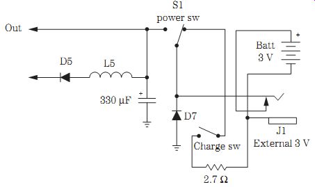
FIG. 12 The battery and ac power supply circuits found in a portable CD player.
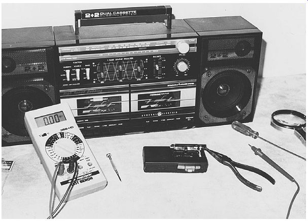
FIG. 13 Locate the power transformer within an AM/FM/MPX cassette player to
find the power supply components.

FIG. 14 Early auto radio and cassette player power supply components.
Locating low-voltage components
Cassette players, CD players, and ac adapters use very small power transformers.
Locate the power transformer and electrolytic capacitor with the silicon diodes nearby. The transformer may be mounted off to the side or off the main PC board in cassette and CD players (Fig. 13). When the power transformer is mounted to one side or off the main PC board, trace the secondary leads to the power supply circuits.
Check for a transistor voltage regulator and zener diode nearby in a voltage regulator circuit. The power supply circuits are found next to the power transformer and the largest electrolytic capacitor on the PC board chassis.
Servicing car radios
Some of the early car radio power supply circuits were quite simple and were fed from a 12-V car battery to a choke coil, low-ohm resistor, and the main filter capacitor. The on/off switch applied power to the radio circuits with a 5- to 10-A fuse in series with the A cable. In larger auto radios, a decoupling resistor and electrolytic filter capacitor network were found to separate the radiofrequency (RF) and inter mediate frequency (IF) stages from the audio circuits. The AM and FM front-end circuits were operated at a lower dc voltage (Fig. 14).
In deluxe auto receivers, you may find transistor and zener diode regulator circuits.
A deluxe auto receiver may operate on a 2- to 5-A fuse, on/off switch, inductance filter, and several electrolytic capacitors and low-ohm resistors to provide the different voltage sources. A function switch applies the required voltage to the AM and FM radio circuits. Another switch may turn on a cassette or CD player when a cassette or CD is inserted into the auto receiver. Several zener diodes and one or two transistor voltage regulators can provide critical regulated voltage to the front-end (AM/FM) and audio preamp circuits.
Check the input dc voltage at the switch and at the largest filter capacitor on the chassis (Fig. 15). Usually the bottom cover must be removed to get at the main filter capacitor terminals. You also can check the highest dc voltage fed to the audio power output transistors or IC component. Go directly to the RF AM section power supply voltage source when the AM section is weak or dead. Likewise, check the voltage fed to the FM section when only a weak or no FM radio can be tuned in. Suspect a defective transistor or IC voltage regulator when there is no output voltage at the emitter terminal of the regulator transistor or the output terminal of the regulator IC.
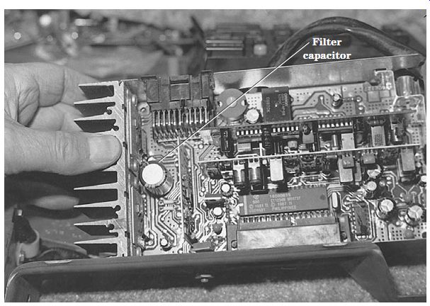
FIG. 15 Locate the largest filter capacitor within a car radio and take critical
voltage tests.
DIODE TESTS
Silicon and zener diodes can be checked within the circuit if a coil or low-ohm resistor does not shunt across the suspected diode. You should have a low measurement with the positive probe of the DMM at the anode terminal and the black probe at the collector terminal with the diode tester of the DMM. No measurement with reversed test lead probes indicates a normal diode. The positive probe of a volt-ohm-milliameter (VOM) is just the reverse of the DMM. A low-ohm measurement on the VOM with the positive probe at the collector (+) terminal of the diode indicates that the diode is normal (Fig. 16). Replace a defective diode with a low-ohm measurement in both directions. Remove one terminal of the diode from the PC board for a correct resistance measurement when in doubt.
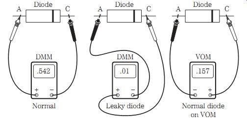
FIG. 16 A normal or leaky diode test with the DMM and a normal diode test
with the VOM.
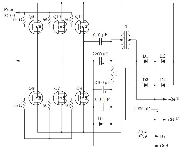
FIG. 17 A MOSFET power supply circuit located in a 170-W auto stereo amplifier.
MOSFET POWER SUPPLY
Metal-oxide semiconductor field-effect transistor (MOSFET) power supply circuits are found in the latest high-wattage power amplifiers to provide a higher dc voltage than the 13.8-V dc battery voltage in the automobile. Several high-powered MOSFETs operate in a parallel push-pull transformer circuit. A bridge silicon rectifier circuit is found in the secondary side of power transformer T1. Very large filter capacitors provide a smooth positive and negative output voltage to the high-powered output transistors within the amplifier circuits (Fig. 17).
KEEPS BLOWING THE FUSE
Suspect a defective power output transistor or IC when the fuse will not hold after re placement. Sometimes a low-amp fuse will open for no reason at all. Simply replace the blown fuse. Do not replace the blown fuse with a larger-amp fuse. Check the output circuits for defective components. Test each output transistor with the diode tester of a DMM. Check the resistance across the largest electrolytic capacitor for a low reading.
Large filter capacitors and a grounded A lead can keep blowing the main fuse. If the radio harness is melted down, go directly to the transistor output stages. Test and re place the leaky or shorted transistors. Always check the fuse holder or auto fuse container for the correct size fuse.
Servicing high-powered amp circuits
Large stereo amps, from 10 to 50 W, are found in AM/FM receivers, auto radios, cassette decks, CD players, CD changers, and TV chassis. Locate the large filter capacitors, and check the voltage across their terminals. Most of these high-powered amps have a power transformer with full-wave and bridge rectifier circuits. Large power transformers are found in higher dc voltage sources that operate high-powered transistors and IC components. Check for defective transistor, IC, and zener diode regulator circuits supplying several different voltage sources (Fig. 18). Do not overlook an open or leaky decoupling electrolytic in a dead receiver.
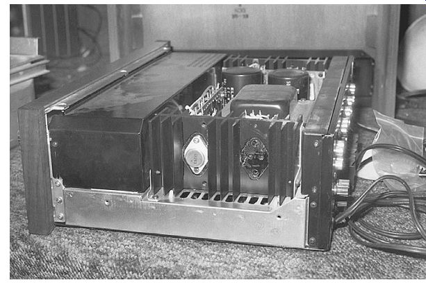
FIG. 18 You will find several different voltage circuits with transistor and
zener diode regulators within a large stereo amp receiver.
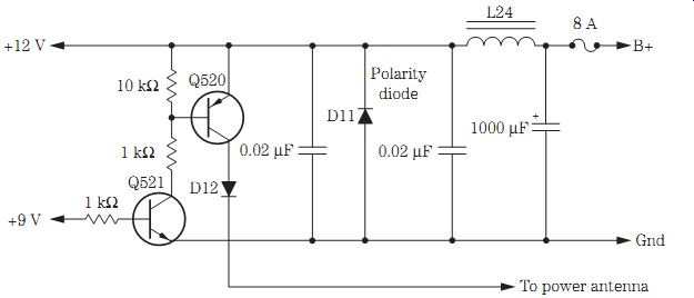
FIG. 19 Check for leaky transistor regulators within the stereo circuits of
an auto AM/FM/MPX cassette receiver.
Some of these large stereo units are fused, and some are not. Check for an open fuse when there is a dead chassis. Measure the dc voltage across the large electrolytic capacitors because they filter out the various voltage sources. Take a quick ESR test of each electrolytic in the power supply. Always discharge each electrolytic before taking any ESR tests. While in the same circuits, measure the resistance across the large filter capacitor terminals, which may indicate a shorted or leaky capacitor or a defective component in the power source. Test each silicon diode with the diode tester of a DMM.
Now check each transistor voltage regulator with the diode tester of the DMM.
Sometimes an overloaded circuit can cause extensive damage to the power supply.
Check the resistance across each electrolytic in the power supply for a measurement under 50 ohms. Cut into the output voltage PC trace or wiring that may be overloaded and then take another measurement. Overloaded circuits connected to the power sup ply are caused by high-powered output transistors and ICs and leaky transistor regulators and zener diodes (Fig. 19).
THERE SHE GOES AGAIN
Electrolytic capacitors have a tendency to blow their top, so to speak, with higher than normal voltage applied and gas buildup inside them (Fig. 20). The electrolytic can become warm and blow its top off if the polarity is reversed or it is installed back ward. Small electrolytic capacitors can run too warm when a lower voltage capacitor replaces one of higher working voltage.
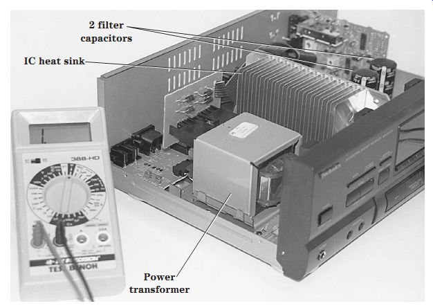
FIG. 20 Visually inspect the electrolytic capacitors for blown or bulging
sides in large stereo amp power supplies.
When replacing electrolytic capacitors, make sure that the working voltage is the same or higher. Likewise, replace defective electrolytics with ones of the same capacity or higher. Check for correct polarity before soldering. These electrolytic capacitors can blow up in your face. Excess tinfoil and insulating material may be found over the en tire chassis when the top blows off.
Power transformer problems
Suspect leaky diodes, bridge rectifiers, filter capacitors, power output transistors, or ICs when a fuse blows. Go directly to the large filter capacitor and take a resistance measurement across it. The meter hand should charge up and discharge with a very high measurement. Low-ohm readings below 1 kilohm can indicate a leaky or shorted capacitor. Here the electrolytic capacitor measures no voltage across the terminals.
Check each diode within a bridge rectifier or full-wave rectifier circuit. A low-ohm measurement is noted in one direction. If the reading is low with reversed test leads, re move the suspected diode and test it out of the circuit. Replace the whole bridge unit when one diode is found to be leaky or open.
Sometimes the power transformer can be damaged, can run warm, or can blow the main ac line fuse. If the transformer is overheating or extremely warm, disconnect all leads going to the diode circuits. Mark each color-coded wire so that it can be replaced correctly. Then power up the transformer. If it runs warm or hot without a load, replace it. Remember, these transformers are quite expensive and sometimes difficult to obtain (Fig. 21).
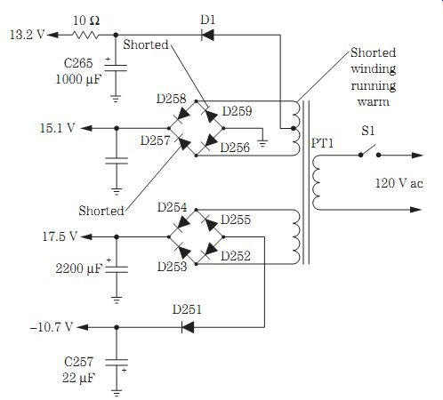
FIG. 21 Shorted D257 and D259 caused damage to the secondary winding of a
transformer (PT1) in a Sanyo GXT-300 stereo system.
EXCESSIVE HUM
Shunt all electrolytic capacitors with a known electrolytic across the suspected filter capacitor in the power supply circuits. Clip the new electrolytic in the circuit before firing up the AM/FM receiver so as not to destroy other electronic components. Excessive hum was heard in the speakers of a Sharp SC700CR receiver with no tuner action. Replacing a 470- uF filter capacitor near the heat shield solved the hum problem.
HIGH- AND LOW-VOLTAGE SOURCES
A very loud hum usually is caused by one or two filter capacitors. Check the electrolytic capacitor with the ESR meter, or shunt another capacitor across the suspected one. In both cases, discharge each electrolytic. Maintain correct polarity when installing or shunting another capacitor. The negative terminal ties to the common ground side and at ground potential. Replace all electrolytic capacitors in the power supply that have changed values, have ESR problems, and may be leaky or shorted.
A low hum can be caused by defective electrolytic capacitors and burned resistors in the decoupling stages. Locate these capacitors on a separate board with the bridge rectifiers. Weak and distorted audio can result from improper positive and/or negative voltage applied to the power output ICs or transistors. In large amps, a high positive (+40 V) and negative (-40 V) voltage may be applied to the power output semiconductors (Fig. 22).
Leaky zener diodes and transistor voltage regulators can cause weak and distorted sound.
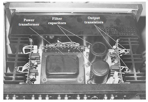
FIG. 22 Check all electrolytics within large stereo amp power supplies with
an ESR meter.
BAD POWER SWITCHES
Dirty or worn switch contacts within an electronic product can cause intermittence or a dead chassis. Suspect a bad off/on switch when the unit intermittently shuts off.
A badly soldered joint on one of the wires connected to the switch can produce intermittent operation. Sometimes the receiver turns on okay, and the next time it is dead. A dirty on/off switch also can make the relay kick off and on. Check for open foil or traces where the power switch ties into the power line. Resolder all switch terminals. Suspect a bad power switch when the product cannot be turned off and operates all the time (Fig. 23).
Replace an on/off switch when the switch contacts began to arc over and a loud buzzing noise is heard in the speakers. A chattering relay may be caused by a dirty or worn power switch. A dead receiver may result from an arcing power switch. Replace the on/off switch if a noisy sound is heard when the unit is first turned on.
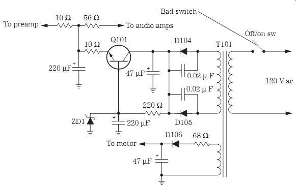
FIG. 23 A dirty or worn power switch can cause intermittent operation and
a noisy sound when turned off and on.
NO POWER SHUTOFF
The power could not be turned off with the regular switch (S504) in a Soundesign 5959 cassette stereo amplifier. The switch tested normal. In this model, the power turnoff circuits are found in the low-voltage power supply. The same voltage was found on all three terminals of Q604. Replacing transistor Q604 with an ECG374 universal replacement solved this unusual power turnoff problem.
Repairing CD player power supplies
Small portable CD players can be operated from batteries or an ac adapter, whereas larger players have a power transformer. Some power transformers are quite small in size with several different ac windings. A power transformer is mounted on the chassis, whereas other power supply components are mounted on the main PC board (Fig. 24).
You may find three or more secondary ac windings on the transformer with full wave, half-wave, diode, and bridge rectification. Often, only one diode is used as a half wave rectifier to furnish higher voltage to the control and display circuits. Different voltage sources may be needed for servo, decoder, control, and display circuits. Positive and negative voltages are found with each bridge rectifier circuit.
In larger CD players, the power supply may contain several transistors and IC regulators. Dc-dc power supply circuits are found in larger CD player power supplies. Usually the dc-dc power supply provides higher separate positive and negative voltages to the CD circuits.
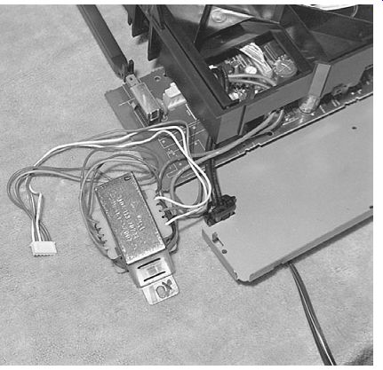
FIG. 24 The shorted ac power transformer within a Magnavox CD changer.
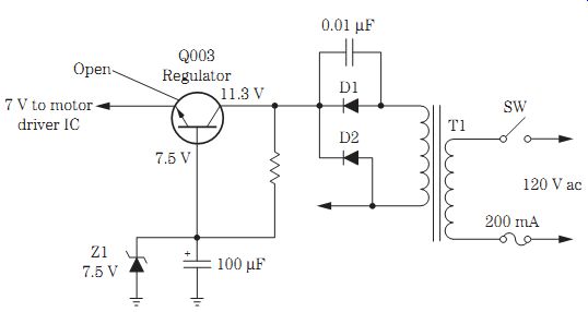
FIG. 25 The loading motor in a Goldstar GCD-616 CD player was dead as a result
of an open 7-V regulator transistor.
NO LOADING, GOLDSTAR CD PLAYER
The loading motor would not load a CD in a Goldstar GCD-616 CD player. Since no schematic was available and a voltage check across the motor terminals was zero, the motor terminals were traced back to a motor driver IC. No voltage was found on any terminal of the driver IC.
Since there were several different power sources within the transformer circuit, all diodes were quickly checked with the diode tester of a DMM. All diodes tested okay in circuit, and a dc voltage was found on each diode. Next, all transistor voltage regulators were tested in the circuit with the diode tester of a DMM. Q003 did not add up. No voltage was found on the output terminal of Q003. Replacing Q003 restored the 7-V supply source to the loading motor IC (Fig. 25).
IC voltage regulators
Some units use a combination of transistors, zener diodes, and ICs for the different voltage sources. Look for the transistor, IC, and zener diode regulators next to the large filter and decoupling capacitors. Usually all power supply components are found in one corner bunched together, including separate diodes and bridge rectifiers.
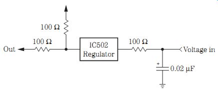
FIG. 26 A simple IC voltage regulator circuit.
An IC regulator can become leaky and produce a lower or higher output voltage. If it is leaky, an IC regulator may run warm. If it is open, no voltage will be found at the out put terminal. Check for a higher voltage at the input terminal and a lower voltage at the output terminal. If the output voltage is low after replacing the IC or transistor regulator, suspect a leaky component tied to the voltage source. When one of the positive or negative voltages is low or missing, suspect a defective IC regulator (Fig. 26).
Servicing color TV power supplies
Before attempting to service a TV chassis, plug it into a variable-isolation power transformer. Early TV chassis operated from a transformer, whereas the latest TVs operate directly from the power line with a power line voltage regulator circuit. Of course, today's color TV chassis may have a switch-mode power supply (SMPS) or a switching power supply that operates from a switching transformer. A variable isolation power transformer prevents TV or test equipment damage. Besides, for a chassis that is intermittent or dead, you can raise or lower the ac line voltage to make the TV chassis act up at a lower or higher line voltage than normal (Fig. 27).
The typical ac power supply consists of a bridge rectifier, a filter capacitor, voltage regulators, and a fuse (Fig. 28). Some chassis have one diode with half-wave rectification. Look for the ac and dc line fuse and bridge rectifier circuit on the PC board main chassis. A large high-voltage electrolytic capacitor (330 to 870 uF) is found nearby.
Voltage regulator transistors and zener diodes can be found around the electrolytic de coupling capacitors. In the latest TV chassis, look for a large voltage regulator IC sup plying high dc voltage to the horizontal output transistor.
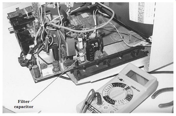
FIG. 27 Check for a line voltage regulator and a large filter capacitor in
a TV chassis to locate the power supply components.
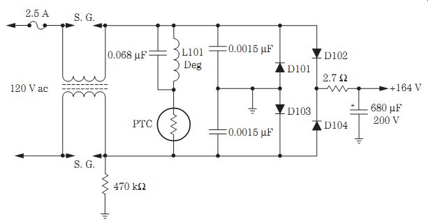
FIG. 28 The typical ac power supply circuit in a present-day TV chassis.
POWER LINE IC VOLTAGE REGULATOR PROBLEMS
Intermittent chassis shutdown can be caused by a defective line voltage regulator.
Foldover at the top of the picture and a raster that is shrunk on all sides can result from a bad STR30110 IC regulator. A dead chassis and okay fuse symptom can be caused by a defective regulator. A leaky line voltage regulator may not allow the TV to turn off, or the TV may shut off at once with a leaky line voltage regulator.
A color TV may come on with a loud hum and then shut down when it has a defective high-voltage line regulator IC. The TV may shut down intermittently at turn on or may operate for several minutes or an hour and then shut down as a result of a defective IC regulator. Suspect a defective line voltage regulator when the TV shuts down with the power line voltage above 110 to 115 V ac (Fig. 29).
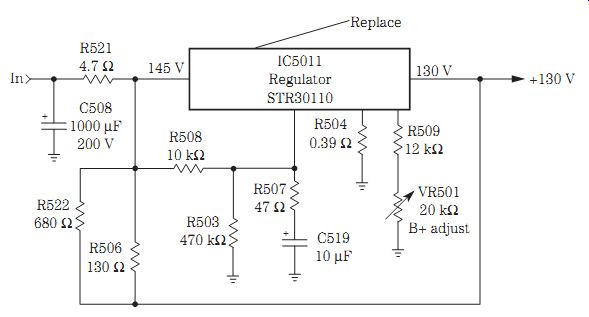
FIG. 29 Replace a defective line voltage regulator in an Emerson TS2555SD
color TV when it is dead, goes dead after a few minutes, or comes on in
10 minutes before shutdown.
The line voltage regulator and main filter capacitor can cause the picture to shrink on all four sides of the screen and may cause the set to operate intermittently. Suspect a line voltage regulator when the horizontal output transistor runs warm with poor regulation and intermittent startup. Check the line voltage regulator when the TV shuts down at a normal power line voltage. Replace the line voltage regulator (STR30110) when the set comes on intermittently, the power relay clicks, and the set goes into chassis shutdown.
A dead chassis can result from a defective line voltage regulator. A pulsating picture with poor voltage regulation also can be caused by a bad line voltage regulator.
Badly soldered joints on the line voltage regulator terminals (STR30125) can intermittently shut the TV off. An STR30135 line voltage regulator IC can pull the sides in and cause the vertical sweep to change. A dead TV with a blown line ac fuse can be caused by a shorted line voltage regulator IC.
Shadow-like lines floating upward through the picture can result from a defective STR30130 IC regulator. Wavy lines and poor voltage regulation can be caused by a bad STR30130 regulator. A pulsating picture, intermittent with the sides pulled in, can be caused by a defective line voltage regulator.
Hum in the audio and shutdown at high ac power line voltages can result from a bad IC regulator. Two horizontal lines floating up the picture can be caused by a defective 130-V line regulator IC. Suspect a defective line voltage regulator when the brightness is increased and the picture begins to pulsate.
TROUBLESHOOTING TYPICAL POWER SUPPLY CIRCUITS
Look at both the ac and dc fuses. Check for B+ voltage at the collector terminal (metal body) of the horizontal output transistor or across the large filter capacitor terminals. Low or no voltage at the output transistor can indicate an open dc fuse or a defective voltage regulator. If dc voltage is not found at the large filter capacitor, check for an open or leaky diode, a high-wattage isolation resistor, or poor ac wiring connections. Measure the ac voltage at the large resistor and common ground. One or more leaky diodes in the bridge circuit can cause the power line fuse to open. Be careful, this is power line voltage you are measuring.
If the main line fuse keeps blowing, suspect a leaky or shorted diode in the bridge rectifier circuit. When both fuses open, suspect a defective horizontal output transistor or voltage regulator IC. Don't overlook a burned isolation resistor in the flyback primary winding.
Heavy dark lines across the raster can indicate a defective main filter capacitor or regulator. Clip another electrolytic capacitor across the suspected one with the power off. Watch for correct voltage, capacity, and polarity before clipping in the capacitor. Re place a defective regulator when lower dc voltage and hum bars appear in the raster.
These IC regulators have a tendency to open or appear leaky.
Lower output voltage from the voltage regulator may be caused by overloading in the horizontal output and flyback circuits. Remove the horizontal output transistor, and test the voltage regulator source. If it is normal, this voltage will be a little higher with the horizontal load removed. Replace the voltage regulator if the voltage is still low after removing the horizontal output transistor and the input voltage to the regulator is fairly normal.
Today, the new line voltage regulator consists of a transistor with five terminals. You can spot a line IC regulator because it has numbers stamped on the body. The last three numbers are the output voltage. The dc input voltage may vary from 145 to 175 V, de pending on the filter capacitor and surrounding components. An STR30125 fixed line regulator has an output voltage of 125 V. Test the dc voltage going into the regulator and the fixed output voltage. If the right voltage is going in and improper voltage is coming out, suspect a defective regulator. Check all components that are tied to the regulator terminals.
RELAY SWITCHING PROBLEMS
Some TV chassis employ a power relay to turn on the chassis, whereas others use a relay to start the degaussing process. A defective relay can cause a dead TV chassis. An intermittent relay can cause the TV to start up and then shut down. Replace the ac relay when the set comes on okay and then shuts off after 5 minutes. When the TV shuts off intermittently and then sometimes comes back on by itself, suspect badly soldered joints of the relay on the ac power line side (Fig. 30).
The chassis goes dead and the relay clicks when there are bad switching points on the power relay. Badly soldered joints on the relay coil can produce a dead-chassis, okay-fuse symptom. Suspect an open relay coil with a dead TV chassis and no click of the relay. In a Zenith SMS1935 chassis, the relay did not click, and this was caused by an open relay winding.
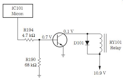
FIG. 30 TVs with a switching relay can have many startup and shutdown service
problems.
Do not overlook a shorted diode across the relay solenoid when the relay will not even click. Bad relay contacts can cause intermittent shutoff, not shutdown, and the set may play 30 minutes or so. Check the relay driver transistor when the TV is dead and there is no click from the relay. Suspect a bad relay when the TV cannot be turned off and the set must be unplugged from the power line. The relay points may be stuck in one position. Check for a bad relay when the TV comes on when first plugged in. A Magnavox 19F1 chassis could not be turned off and had to be unplugged to turn the set off; this was caused by a defective relay.
The audio went out and the raster stayed on when a TV with a bad relay was turned off. Bad contacts on the relay caused a dead TV with a relay click and the LED channel display still on. Suspect a relay driver transistor when a TV shuts off and not a shutdown symptom. A dead TV chassis with a clocklike ticking sound that was heard if the set was left on was caused by a bad filter capacitor (33 uF, 160 V) in the relay driver circuit. Suspect a bad driver relay transistor when the TV cannot be turned off in remote operation.
Replace relay driver transistor (Q108) when an Emerson TS2761 TV is dead, the fuse is okay, and there is no relay click.
Suspect a relay driver transistor or memory IC when the relay chatters constantly.
A chattering relay may be caused by a defective electrolytic in the voltage supply circuit. Check all electrolytics in the relay circuits with an ESR meter. The clocklike clicking noise can be caused by large filter capacitors in the relay driver circuits.
Double-check all silicon and zener diodes when the relay begins to chatter after the TV operates for 5 or 10 minutes.
Check for a badly soldered joint on a low-ohm resistor in the power supply when a TV is dead and the relay begins to make a chattering sound. Suspect electrolytic capacitors in the power supply when the picture shrinks on both sides and the relay chatters.
A dead Sanyo DS13530 TV was damaged by lightning, and D002, the relay driver transistor (Q023), and an open trace on the power line to D002 were replaced and repaired.
TROUBLESHOOTING SCR SWITCHING REGULATOR CIRCUITS
In early ac chassis, the silicon-controlled rectifier (SCR) regulator was used to control the dc voltage applied to the horizontal driver and output transistor. The ac input circuits are the same as the typical low-voltage circuits, except an SCR with driver, phase detector, and error amp provide adjustable B+ voltage. In other SCR circuits, the IC regulator with B+ adjust can be found in the derived voltage circuits of the horizontal output transformer.
Often the horizontal circuits must perform before B+ regulation at the B+ voltage source. A primary winding of the flyback is connected after the main filter capacitor and bridge rectifier in series with the SCR switching regulator. B+ can be regulated with the B+ adjust control to set the correct voltage to the horizontal output circuits. Suspect a defective voltage regulator circuit or horizontal output component when the B+ control has no effect in changing the B+ voltage.
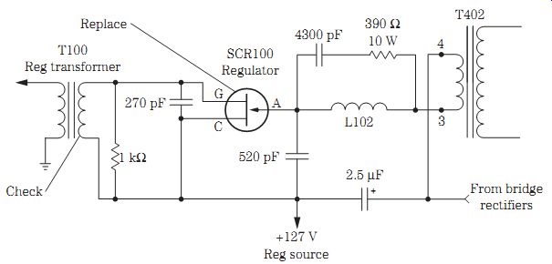
FIG. 31 Early SCR regulator circuits found in the power supply of an RCA CTC121
chassis.
SERVICING SCR REGULATOR CIRCUITS
Check for an open ac fuse (F501). If it is open, check the diodes in the bridge rectifier circuits. Measure the dc voltage across the main filter capacitor (C505). Suspect SCR100, T100, and associated components if there is no voltage at the output source (Fig. 31). Measure the dc voltage at the anode terminal of SCR100. No voltage can indicate an open winding of the flyback or bad connections at the PC board. Measure the resistance of the flyback winding. An open winding or poor connections can pre vent 165 V from reaching the anode terminal.
If 165 V is found at the anode terminal of SCR100 and there is no or low gate voltage (119 V), check the IC regulator, zener diode, and associated circuits. Check waveforms and voltages on the SCR driver, phase detector, and error amp when attached to the SCR regulator circuits. Check voltage sources from the horizontal out put transformer and horizontal circuits when B+ cannot be found at the cathode terminal of the SCR regulator. Don't overlook the IC power regulator in the horizontal flyback circuits.
DEAD CHASSIS, SCR4101
The chassis was dead in an RCA CTC159 TV, and the voltage on the horizontal out put transistor was around 155 V. This meant that the raw dc voltage from the bridge rectifiers was normal. A voltage check on SCR4101 indicated +167 V at the anode terminal and no voltage on the collector terminal. The output voltage across C4120 (33 uF) should be around 125 V (Fig. 32).
A continuity test was made across the primary winding of T4101 and was normal.
CR4102 and R4115 tested good. On checking SCR4101 in the circuit, no diode test was found across any two different terminals. SCR4101 was replaced with an ECG5424 universal replacement, and the chassis came alive. Do not overlook CR4104 in the 33-V source for a dead-TV symptom.
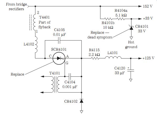
FIG. 32 A defective SCR4101 in an RCA CTC159 chassis caused a dead TV symptom.
TV STANDBY CIRCUITS
TV standby circuits provide a voltage source at all times so that the remote control will operate. Go directly to the remote infrared (IR) circuits when the remote can not operate or turn the TV chassis on. In some TV chassis, the remote IR pickup system and system control IC provide a standby switch with on/off switching transistors to operate the remote features (Fig. 33).
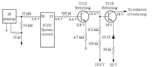
FIG. 33 The IR standby circuit originates within the system control IC101
that controls a standby switch and on/off switch transistors.
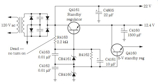
FIG. 34 R4163 had increased from 1200 to 1720 ohms and caused a dead symptom
in an RCA CTC167 chassis.
The dead TV chassis with an okay fuse may be the result of bad silicon diodes in the standby power supply. When a TV is turned off and the sound goes off but the picture turns black and white, this may be caused by a zener diode in the standby circuits. Check for open low-ohm resistors within the standby circuits when a TV is dead and the line fuse is open.
The standby power supply is on all the time and provides voltage to the control circuits so that the remote control can turn the TV on. Usually a small standby power sup ply and bridge circuits provide the required standby voltage. The small power transformer may be fused but is wired directly to the ac power line. The standby voltage provides 5 to 20 V dc to the control circuits.
Suspect the standby circuits when a TV can be turned on manually but not with the remote. Locate the standby transformer and the corresponding parts nearby (Fig. 34). Locate the standby transformer fuse and bridge rectifiers. Visually trace the trans former leads to the bridge rectifiers. You may find a combination transistor and zener diode regulation circuit in the output voltage source. Sometimes this transformer and fuse are located on a separate metal chassis. The protection fuse may be in the primary or secondary winding of the transformer.
INTERMITTENT STARTUP AND SHUTDOWN SYMPTOMS
Intermittent startup and shutdown symptoms found in a TV chassis are very difficult to resolve. By monitoring the power supply voltage sources and horizontal wave- forms, you can sneak up on the defective component. Monitor the raw dc power line voltage from the line voltage regulator IC.
Suspect a fusible resistor (47 ohms) at one of the pin terminals on an STR30125 regulator for a narrow picture when the TV changes channels or when the TV goes off and on intermittently. A bad flyback can cause the TV to play for days, then intermittently shut off, and maybe not come on again. Check the line voltage regulator for shut down when the power line voltage is greater than 110 V ac. Do not overlook an intermittent transistor voltage regulator for shutdown symptoms. Check for a bad relay when the TV intermittently shuts off.
Check all electrolytic capacitors within the power supply with an ESR meter for intermittent startup. A bad IC regulator can cause a momentary startup and then shut down. Suspect an STR30130 IC regulator when the TV shuts down after warmup and the relay clicks off and on. Check for a defective line voltage regulator IC when there is a shaky picture and the TV sometimes turns on with loud volume and intermittently shuts down. Suspect a bad system control IC or microprocessor when the TV starts up intermittently, the channels do not lock in (or sometimes do with the wrong channel number), and the sound is normal.
Small 4.7-uF, 50-V electrolytics with bad ESR problems caused a TV chassis to shut down at once. Check all electrolytics in the power supply with an ESR meter when a TV that is left on begins to chug-chug and sometimes starts up or pulses off and on. When a TV shuts down around 95 V and operates at 90 V ac, suspect a defective STR30130 IC regulator. Check for a badly soldered joint when a TV tries to start up and shuts off.
Replace the voltage transistor regulator and diode in the secondary voltage sources of a TV when the power switch is pushed and the TV appears dead and sometimes comes on later or at once. Do not overlook a defective startup transistor when a TV intermittently starts up or there is no startup. A defective EEPROM IC can cause a TV to come on momentarily, the high voltage to go dead, and then the unit not to start up.
When a TV shuts off intermittently, suspect a defective hold-down or safety capacitor in the horizontal output circuits. Check for a leaky zener diode in the power supply regulator circuits when a TV shuts off and does not shut down. Badly soldered joints on pins 1, 2, 3, and 10 of the flyback can cause a TV chassis to be intermittently dead, not turn on, and after 2 or 3 hours to start up again. A badly soldered joint on R404 and R405 (20 kilohm, 3 W) connected to T400 on the SMPS circuits caused a Ward's 26B1 TV to turn off (not shut down) intermittently and the LED to blink and then slowly fade away.
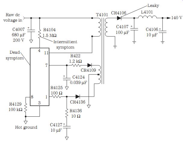
FIG. 35 Always take critical voltage measurements from the capacitor's (C4007)
common hot ground in an RCA CTC187 chassis on the hot ground side.
SWITCH-MODE POWER SUPPLIES
Several different types of SMPSs are found in various TV chassis. In the RCA CTC130 chassis, a variable-frequency switching power supply (VIPUR) is found, and a switch-mode power supply is found in the Sylvania C9 chassis. The ac input transformer circuits are above ground and sometimes are called a hot ground connection. A diamond-shaped form represents a common hot ground. The components found on the secondary winding of the transformer use a regular negative ground symbol.
The raw dc voltage from the bridge rectifiers is fed to the primary winding of the power switching transformer (T4101) in the latest RCA CTC187 chassis. In other TV chassis, a heavy duty transistor works in a regulator circuit, whereas the IC component (U4101) serves as the dc regulator. All primary components on the transformer input circuits operate on the hot ground side.
The components found in the secondary of the power transformer (T4101) work in a common ground circuit (Fig. 35). Always use the negative terminal of an electrolytic capacitor (C4007) when taking voltage measurements in the primary winding. Likewise, use the common negative ground on the secondary side for correct output voltage sources.
A badly soldered joint on the silicon diode in an SMPS caused intermittent startup with a squealing noise at turn-on. A pulsating noise was heard in the sound and was caused by a defective silicon diode in the SMPS. The TV chassis was dead, and the power light came on and stayed on even when the TV was turned off. This was caused by a shorted zener diode in the SMPS.
Check all electrolytics in the power supply circuits and flyback secondary voltage sources when the TV will operate for days, shuts off, and will not come on again. Check the electrolytic filter capacitor with an ESR meter when a TV does not start up or may start up with a thumping noise in the speaker, the sides of the picture are pulled in, and there is very low B+voltage. Check for leaky diodes, open resistors, bad electrolytic capacitors (47 uF), and a defective output transistor in the SMPS circuits when the chassis is dead.
Check the switch-mode regulator transistor, resistors, and horizontal output transistor for a dead chassis symptom. Test the switch-mode output transistor, and look for a change in resistors or a leaky horizontal output transistor when a TV chassis is dead and the LED display goes on and then goes off after 10 seconds or so. Intermittent startup in a Zenith SE2505 TV was caused by badly soldered joints on Q3410 and C3413 (100 uF, 25 V).
SMPS, RCA CTC140 CHASSIS PROBLEMS
A dead RCA CTC140 chassis can result from a defective regulator (U4100) and Q4100 output transistor. A leaky Q4100 transistor can burn or open resistor R4111.
An intermittent turn-on and turnoff symptom can be caused by a defective CR4101.
A shorted CR4701 can cause an intermittently dead symptom. Resolder all secondary diode terminals for dead or intermittent operation (Fig. 36).
TV switching circuits
The latest switching power supply circuits are found in the latest color TVs and TV/VCR combos. A raw dc voltage is fed from a bridge rectifier circuit in the primary winding of transformer T801. Filter capacitor C805 (470 uF, 200 V) filters out the ripple within the dc power supply. IC801 provides the switching action in the primary winding of T801. A hot ground is found on the components that are connected within the primary winding of T801. Use the negative terminal of C805 for all common hot ground voltage measurements (Fig. 37).
Separate secondary windings of transformer T801 provide several different voltages to the various TV circuits. A fixed silicon diode with electrolytic filter capacitors rectifies and filters the ac voltage in the secondary sources. Always use the common ground found at any filter electrolytic in the secondary voltage sources when taking critical output voltage measurements. If not, the voltages measured will not be accurate.
DEAD TV, PANASONIC TV/VCR COMBO
A Panasonic PV-M1327 TV/VCR combo came in with a dead chassis. No voltage was found on the silicon diode in the transformer (T1001) secondary circuits. A higher than normal dc voltage ( +139.5 V) was found on the collector terminal of the switching transistor (Q1001). Q1001 was found to be open with a quick diode test with a DMM. At the same time, Q1002 tested okay. Replacing switching transistor Q1001 solved the dead TV/VCR chassis (Fig. 38).
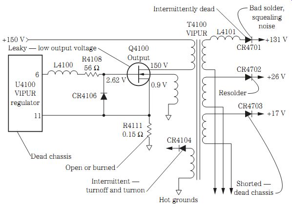
FIG. 36 The various service problems found in an RCA CTC140 chassis SMPS.
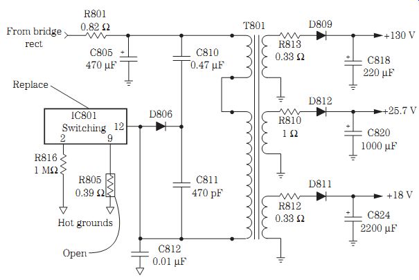
FIG. 37 A dead symptom in a Panasonic CT-31S185/CS TV was caused by an open
R805 (0.39 ohm) resistor and a defective IC801.
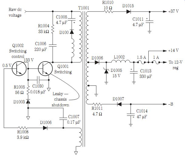
FIG. 38 Leaky switching transistor Q1001 in a Panasonic TV/VCR caused a TV
shutdown symptom.
TV/VCR switching circuits
The TV/VCR switching power supply circuits may contain all the TV and VCR voltage sources or just the TV circuits. A raw dc voltage from the ac bridge circuits is applied to the primary winding of the switching power transformer. Usually a switching transistor and control transistor are found in the bottom leg of the primary winding.
All voltages taken from the primary side should be taken from the negative terminal of the main filter capacitor as the common hot ground (Fig. 39).
All secondary voltages are taken from the common ground in the secondary winding of the switching transformer. The various voltage sources are rectified by silicon diodes and electrolytic capacitors. You will find zener diodes and transistor voltage regulators in the various circuits. Some TV/VCR chassis have a fuse that protects the various circuits.
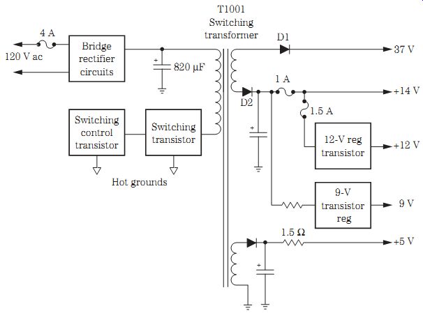
FIG. 39 Take all the primary voltages of T1001 from a common hot ground on
the main filter capacitor (820 uF, 200 V).
TV/VCR SWITCHING PROBLEM, QUASAR
In a Quasar VV1317W model TV/VCR combo, a 1-A fuse was found blown in the secondary winding of the switching transformer (T1001). After replacement, the fuse was blown again. All silicon diodes were quickly checked with the diode tester of a DMM and appeared normal. A quick diode-transistor test on the regulator transistor (Q1051) showed a low reading of 0.17 ohm between the emitter and collector terminals (Fig. 40). Replacing the regulator transistor (2SC3852) with an ECG560 universal replacement solved the blown-fuse problem.
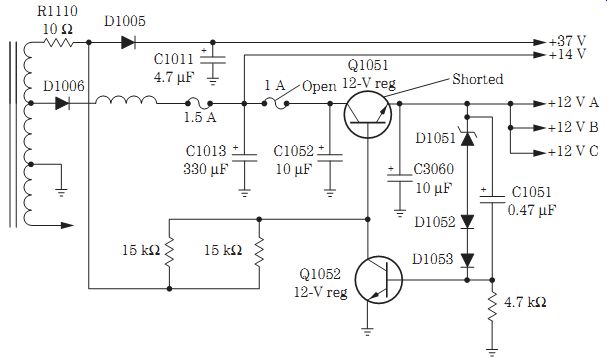
FIG. 40 An open 1-A fuse in the secondary 12-V source was caused by a shorted
12-V regulator transistor (Q1051).
Table 1. Low-voltage troubleshooting.
Check Table 1 on p. 276 for additional power supply problems and solutions.
============