High-powered stereo sound is now found in large AM/FM/MPX receivers, auto radios, and deluxe TVs. A tabletop high-powered receiver may be joined with a CD player to provide 100 to 500 W of entertainment. A five-shelf system may produce 50 to 100 W of power, whereas the auto receiver might have a high-powered amplifier attached with over 1000 W (Fig. 1). Of course, color and projection TVs do not have high-powered sound compared with other consumer electronic products. Many different stereo circuits can be connected to a high-powered surround amplifier and several speakers.
Most high-powered stereo components are laid out in a line to their respective audio channels and are fairly easy to service. When a weak or dead audio channel is found, the defective component can be located with the external amp and scope. Critical voltage measurements in the bad channel can be compared with those in the normal audio channel. The same applies to resistance and semiconductor tests. A quick test of silicon diodes and transistors can be done with the diode tests of a digital multimeter (DMM).
Simply take critical signal in and out tests of the suspected integrated circuit (IC) with the external audio amp or oscilloscope. Defective components can be located and re placed without a schematic or manufacturer's diagram.
High-powered receiver circuits
Although some of the early home tabletop receivers may have 5 to 50 W of power, a deluxe home theater AM/FM/MPX stereo receiver has a 100, 300, or 500 W of power.
A high-powered AM/FM/MPX receiver may have radio circuits plus CD, DVD, CD changer, cassette, or karaoke circuits. Often, lower-wattage receivers employ a higher-powered IC mounted on a heat sink, whereas high-powered units have many high-powered transistors. The AM/FM/MPX circuits are divided at the FM/MPX circuits into right and left audio channels.
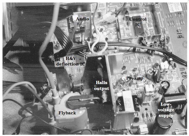
FIG. 1 Try to locate the TV sound circuits on the latest sound IC output components.
When one stereo channel is dead, weak, or distorted, locate the power output ICs or transistors. The stereo signal may be switched manually or electronically by diodes and separate IC components to the two output stereo channels. If the stereo indicator light is not on, you may assume the FM/MPX circuits are not functioning. Check to see if all functions operate, indicating that the trouble lies in the stereo audio circuits.
Locate the defective channel by tracing the speaker connections back to the transistor output or IC component (Fig. 2). Most high-powered ICs and transistors are found mounted on metal heat sinks. Take critical voltage and semiconductor tests to isolate the defective component. Excessive distortion was found after warmup in a Sony STRVX22 receiver and was caused by a defective voltage regulator (STR3091).
DISTORTED RIGHT CHANNEL
The right channel in a 200-W Radio Shack 12-1967 stereo amplifier had hum and distorted audio. The right channel was traced back from the speaker terminal board to a coil that shunted a low-ohm resistor. The coil was tied to two very low ohm resistors (0.15 ohm). The bias resistors were connected to Q209 and Q212. Both transistors were checked with the diode tester of a DMM, and Q212 was shorted. Q211, which is coupled directly to the Q2 driver transistor, also was leaky. The rest of the transistors tested normal. All bias resistors were good. Replacing Q211 and Q212 cleared the distorted right channel.
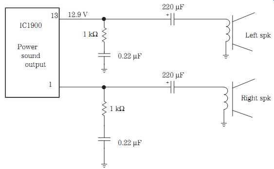
FIG. 2 To locate the power output IC, trace the circuit from the speaker terminals
or the outlet jacks to the suspected power output IC.
Auto stereo circuits
Today's auto stereo radios contain practically the same front-end AM/FM/MPX circuits as any other receiver with cassette and CD player circuits. Most of these audio circuits employ silent switching, with several silicon diodes switching in the receiver, cassette player, and CD player to the left and right audio output circuits. For higher output wattage, the auto radio might be connected to a separate 270- to 1000-W power amplifier (Fig. 3).
If the unit's stereo function is okay but no stereo bulb or light-emitting diode (LED) will light, suspect a defective bulb, improper bias adjustment, defective indicator light circuit, or improper voltage source. The audio signal can be signal traced right up to the stereo indicator circuits. Signal trace the audio to the input of the indicator IC. Take critical voltage tests on the IC and LEDs. Remember, FM/MPX stereo channels can function with a defective indicator circuit.
When indicator lights stay on all the time, the cause is either the indicator light circuitry or an improper threshold adjustment. Usually the indicator light or bank of LEDs is powered by a transistor or IC. Suspect a defective transistor or IC or an improper voltage source when the stereo light stays on very bright (Fig. 4).
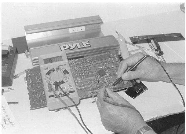
FIG. 3 Remove the printed circuit (PC) board from one end of the metal heat
sink to get at the defective output transistor within a Pyle 750-W amplifier.
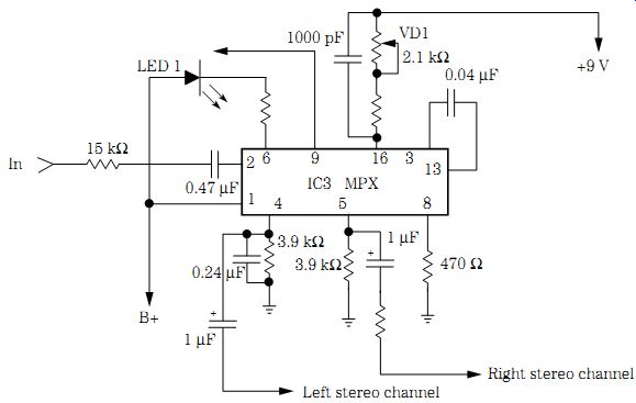
FIG. 4 Suspect the MPX stereo IC when the stereo light does not come on or
is on all the time.
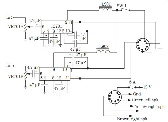
FIG. 5 Early auto receivers had separate power output ICs in each stereo channel.
EARLY AUTO STEREO CIRCUITS
Early auto radio stereo circuits consisted of two or three transistors as a driver and push-pull power output circuits. Early auto IC circuits may use separate power output ICs or a dual IC component. The stereo circuits from the cassette player and radio circuits are switched manually into the input circuits of the power output radio circuits.
A dual volume control applied audio through 4.7- to 10- uF electrolytic coupling capacitors to each input terminal. The audio stereo outputs were connected to a socket found at the rear of the metal chassis (Fig. 5). After a Chevy 21APB1 car radio was on 10 minutes, the radio would pop and go dead. Replacing the intermittent output transistor solved the problem.
AUTO CASSETTE INPUT CIRCUITS
Auto cassette player sound circuits may consist of a single IC that includes both tape head input signals. The audio signal is picked off the tape by the stereo tape heads and fed directly into a dual IC. This cassette audio is coupled to a function switch or has fixed diodes in the line to prevent radio audio from entering the tape circuits.
D101 and D102 isolate the tape head stereo sound from the other audio circuits.
When a cassette is played in an auto radio/cassette player, the sound is amplified and al lowed to pass through two small diodes to the input circuits of the stereo output amplifier. Likewise, when the audio stereo signal is played, the stereo sound cannot enter the tape circuits because D101 and D102 will not let it do so. Fixed diodes are used to switch the two signals, eliminating a radio/tape function switch (Fig. 6).
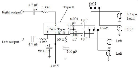
FIG. 6 Check SW-1 and SW-2 when one channel is intermittent in the tape input
circuits in an auto reverse cassette player.
High-powered amps
The power output of a high-powered cassette receiver may range from 16 to 25 x 4 W with a peak root-mean-square (RMS) power rating of 40 to 50 W. An auto CD player and receiver might run from 17 to 23 x 4 W with a peak RMS power output of 35 to 50 W. The auto receiver may be connected to an extremely high powered amp that has 50 x 2 to 500 x 2 W. A bridged-type amplifier may start at 300 x 1 to 1000 x 1 W or higher. The high-powered amp may drive 10- or 15-in woofers with several midrange speakers and up to seven different tweeter speakers (Fig. 7).
The high-powered amp may consist of high-voltage ICs or transistors. In a 250-W amplifier, five power output transistors are found in each stereo channel. All power out put transistors and IC components are mounted on a large heat sink, usually the metal fin body of the amplifier. Each power output transistor can be tested in or out of the circuit. Remove the suspected transistor for accurate leakage testing. Always replace each audio component with the exact replacement part.
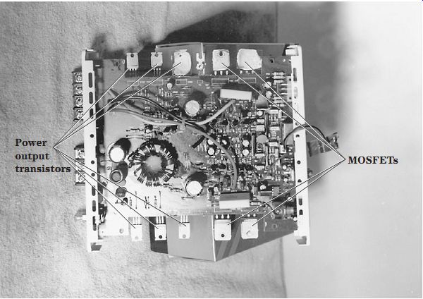
FIG. 7 The high-powered amp connected to an auto radio may contain many power
output transistors.
REPLACING HIGH-POWERED AMP TRANSISTORS
Always try to replace defective audio output transistors with the original part numbers. These parts are easy to obtain if you are a service warranty station for a certain brand of auto receivers. The original output transistors will fit in the same mounting as those that come with the auto receiver. You know that the originals will work in the output circuit every time. Sometimes the same high-powered output transistors can be obtained from electronics mail-order firms.
If universal power output transistors are used, make sure that the part number is correct. Check them out in a semiconductor manual. Make sure that the transistor leads are the same length and are cut before mounting. When removing a defective output transistor, make sure that a piece of insulation is placed between the new transistor and the metal mounting screws and framework. Apply silicon grease on both sides of the insulator, and mount it correctly before trying to install the new transistor. Align the insulator to the correct mounting holes. Make sure that the output transistor is of the correct length and will mount on the holes of the heat sink.
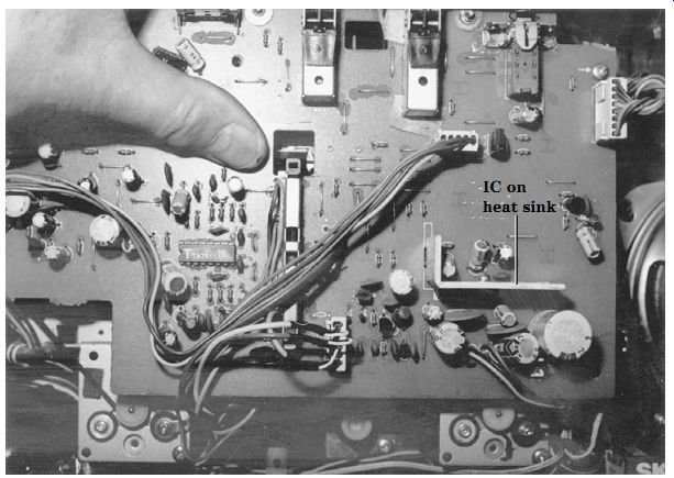
FIG. 8 Locate the output transistors or ICs mounted on a metal heat sink in
a boom-box radio/cassette player.
Portable cassette and radio circuits
Audio stereo circuits are found in boom boxes, cassette players, AM/FM/MPX receivers, and TVs. They are about the same, except that the higher-power-output units require more electronic components and speakers. Although a boom box may have more audio power and several speakers, the front-end circuits are similar to those of table model radios. Some large players can have up to three speakers in each channel. The function switch provides audio from the AM/FM/MPX radio, cassette player, and CD player.
The audio components are easiest to locate in boom-box stereo circuits (Fig. 8).
You will find power transistors and IC components bolted to a separate heat sink or the metal chassis. Locate the output components on separate heat sinks with the audio-frequency (AF) audio section nearby. Wherever you find large electrolytic capacitors and power output capacitors, the audio section is close by.
Portable audio stereo circuits may consist of transistors or ICs or both. Muting transistors can be found at the line output or audio output to the volume control. A right and left meter system may be amplified by one or two transistors from the muting system. The radio, tape, or line output signals are switched into the circuit and amplified by a driver transistor or ICs. Often, a dual audio IC is found for the driver of both audio channels.
In low-powered portable stereo units, a power IC component can be found between the volume control and the speakers. A tone and balance control may be found before the volume control. The dual volume control is found with separate balance controls.
Separate volume controls can be used in some audio circuits. Capacity coupling is found between the volume control and the power IC (Fig. 9).
The audio signal is amplified by IC3 in each channel and coupled through a 220- uF capacitor to the speakers. Most problems in the stereo channels results from a defective IC, a worn volume control, or open coupling capacitors. Weak, intermittent, or no sound can be caused by a defective electrolytic coupling capacitor. Suspect IC3 when either channel is distorted, weak, or dead. Both channels may be affected by a leaky output IC3.
Sometimes only one channel is defective and the other normal. The suspected IC must be replaced in either case. Do not overlook an improper voltage supply source. Low supply voltage can result from a leaky IC3. Replace IC3 if it is running red hot.
CD stereo circuits
CD audio circuits began at the digital-to-analog (D/A) converter IC, are fed to an IC amplifier, and then are fed into line output jacks that are capacity coupled to another power amp IC and into a stereo headphone jack. The audio output circuits are switched into the regular audio stereo circuits in a boom-box cassette player, an auto receiver, and a CD player, with or without headphone reception (Fig. 10). By rotating or pushing the function switch to CD, the audio portion is switched to the internal audio circuits.
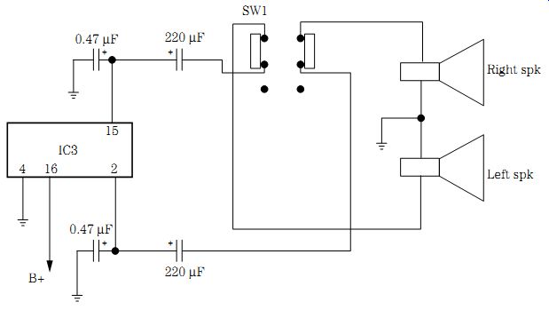
FIG. 9 A dual output IC may be found in the stereo circuits of a boom-box
cassette player.
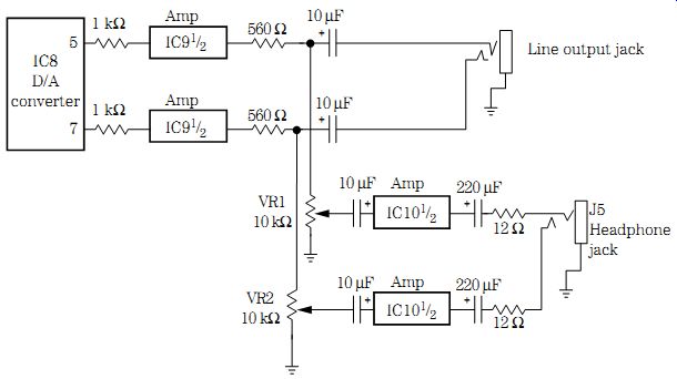
FIG. 10 A portable CD player may contain separate IC components within the
output jacks and headphone circuits.

FIG. 11 A block diagram showing how the signal flows in the right channel
of a CD player.
The audio signal can be traced from the D/A converter IC to the function switch or headphones. Use an external audio amp to signal trace each audio channel at the D/A converter. The audio signal can be traced with the scope with a CD playing. Rotate the function switch to the AM/FM/MPX radio or cassette player to determine if the CD circuits are defective and the audio circuits are normal.
Check the signal at the output of the D/A converter, input sample and hold (S/H) IC, and preamp stages through the low-pass filter network and preamp audio circuit (Fig. 11). When the music stops, check the IC voltage on each terminal.
Leaky audio ICs can run warm and have a low supply voltage. Remember, the CD signal is separated at the D/A converter into left and right audio channels. Muting is accomplished within the line output jacks and controlled by a control processor (Fig. 12).
No muting was found during the program mode in a Sony CDPC70 CD player. No control signal was found at the line output jacks. Replacing the mechanism micro processor IC (8-759-971-410) solved the muting control problem.
Stereo cassette decks
An auto reverse cassette player might have two pickup heads and two different fly wheels in a reverse-play audio system. When the cassette reaches the end of the tape, the player will automatically reverse and play the other track in reverse order. Often the tape head will be packed with excessive tape oxide, and sometimes one or two tape head wires are torn off during operation, with no sound from the channel in reverse order. Double-check the tape heads for packed tape oxide, and clean with alcohol and a cloth. Check each tape head for a broken wire right at the tape head terminal.
The stereo circuits found in cassette decks or players function around two tape heads with audio in the left and right channels. Two tape head windings are found in one tape head to pick up recorded audio to both channels. These magnetic tape heads are fed to identical preamp circuits that amplify the weak signal. This signal is then switched to high-power audio circuits (Fig. 13).
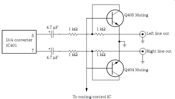
FIG. 12 Suspect muting transistor Q404 when no sound is heard in the right
line output jack.
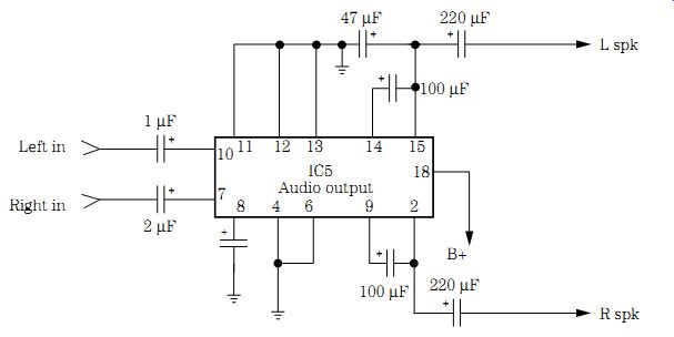
FIG. 13 Check IC5 when the left channel is dead and the right channel is distorted
in an AM/FM/MPX cassette deck.
A dirty tape head can cause weak or distorted sound or a dead channel. Sometimes the head gap becomes packed with excess tape oxide, creating poor pickup to the transistor or IC preamp circuits. Look for broken head wires when one channel is intermit tent or dead. Loss of high frequency can be caused by a worn tape head. Cross-talk is caused by poor adjustment of the tape head (Fig. 14).
Isolate the preamp circuits from the tape head to the function switch. Signal trace the audio with an external amp from the tape head winding to the base of the transistor or the input terminal of the IC. Remember, the signal directly off the tape head is very weak. The audio should be amplified after the preamp and AF circuits. With a 1-kHz test cassette, signal trace with a scope through the entire audio circuit.
A loud rushing noise in the right channel was heard in a Soundesign CD301A cassette player with the volume wide open. On examination, the red wire was found to be broken off the tape head. Resoldering the red wire to the tape head solved the loud rushing noise.

FIG. 14 Clean the tape heads when one channel is noisy and the other distorted.
Hot output transistors
Too-hot-to-touch transistors or IC components can point to a defective audio output circuit. Transistors and ICs that run red hot should be replaced. These power output components can run warm but not red hot. Sometimes a hot IC power output will turn a gray color and may have a piece of plastic popped out of the outside case area.
When a hot output transistor is found, test the driver transistor for a leaky or open condition. Make sure that the power output emitter resistors are of the same value and not burned or open. Take critical resistance and voltage measurements, and compare them with the normal channel.
A 25 x 4-W audio amplifier may have a high-powered IC with four different sound output channels to four different speakers. Usually the amplifier feeds both the left and right front speakers and the left and right rear speakers. Here, two 1000- uF electrolytic capacitors couple the ground speaker returns to each set of speakers. A defective IC10 may result in front left channel intermittence and right front channel distortion (Fig. 15).
It is possible in balanced audio output circuits that no electrolytic coupling capacitors are found between the speakers and the amplifier. When one of the audio output transistors becomes red hot or appears leaky, this also will damage the speakers. The normal balanced audio output circuit has zero voltage at the speaker terminals. If a speaker is found to be mushy with a frozen cone, suspect that some type of voltage has been applied to the speaker or that too much high powered volume has destroyed the speaker voice coil. Quickly measure the dc voltage on the speaker terminals. Do not connect another speaker until the audio amp has been repaired.

FIG. 15 The front left speaker was distorted and the rear right speaker was
weak in a stereo CD and cassette player and receiver.
Dead right channel
When either the left or the right channel appears dead and the other channel is nor mal, signal trace the dead channel with the external audio amp and compare the same signal with the normal channel. If the dead right channel is in a cassette player, insert a cassette and trace the signal with the external amp or scope as an indicator.
Slip a 1-kHz test cassette into the player, and take stage-by-stage signal checks.
Often the dead channel is caused by a leaky or open transistor or IC, bad electrolytic coupling capacitors or power resistors, or low voltage from the power supply.
On large amplifiers, insert a 1-kHz audio generator signal at the input, and trace the signal with the scope. Always keep a speaker connected as a load or a 10-ohm, 10-W resistor on the speaker terminals while servicing the defective amplifier.
In high-powered audio circuits, five or more high-powered transistors are found in each stereo output channel. When a transistor goes open or becomes leaky in directly coupled circuits, the power output transistors may be damaged. A change in resistance can upset the bias on a driver transistor. The leaky bias diode can cause transistors to overheat and be destroyed. Check for burned or leaky zener diodes in the circuit that will upset the whole output amplifier. Suspect a change in resistance, a leaky diode, or an open or shorted driver transistor when the output transistors run red hot and repeatedly become damaged.
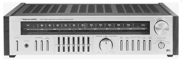
FIG. 16 The right channel was dead in a Radio Shack AM/FM stereo receiver.
When the signal quits, take critical voltage measurements and inspect the parts found around the high-power transistors and ICs. Test the components in-circuit, and when one is found to be leaky or open, remove it and test it again. Look for shorted or open capacitors in the IC power output circuits. Leaky or open electrolytic capacitors in power output circuits can produce a dead channel.
Look for open fuses and burned or open bias resistors in the audio circuits (Fig. 9 16). Check all the transistors in-circuit when burned resistors are found. Remove the suspected transistors, and check the bias resistors while they are out of the circuit. Re place resistors with the exact resistor found in the good channel. Look for power out put transistors on heavy heat sinks.
The right channel was dead in a Sharp RT3388A cassette player; no volume units (VU) meter movement was noted. Signal tracing the right channel with a cassette inserted and then signal tracing each stage located the problem after IC4 was removed.
HOT OUTPUT IC, MEDALLION 63-030
The 3-A fuse was blown in a Medallion 63-030 deluxe auto receiver. The fuse kept blowing after replacement. A resistance measurement across main filter capacitor C321 (1000 uF) showed a leakage of 0.015 ohm. This 13.6 V dc is fed directly to the power output ICs. IC4 showed signs of overheating. Cutting loose the voltage trace to pin 1 of the IC4 (TA7205P) AF amp cleared up the shorted power supply. IC4 was replaced with an ECG1155 universal replacement, and this solved the hot output IC symptom (Fig. 17).
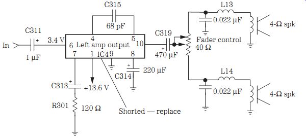
FIG. 17 The hot power output IC4 in the right channel was shorted (0.015 ohm)
at pin 1 and kept blowing the fuse.
Weak left channel
Sometimes the defective component that may be causing a weak symptom is much more difficult to locate. Weak reception can be caused by dried-up coupling capacitors, open emitter bypass capacitors, bad AF and driver transistors, and a dirty tape head. One side of the tape head in a cassette player can cause a weak sound and a low hum. Leaky 4.7- to 10-uF coupling electrolytics or a low-voltage source can cause a weak audio stage. A weak left channel can result from a defective dual power output IC (Fig. 18).
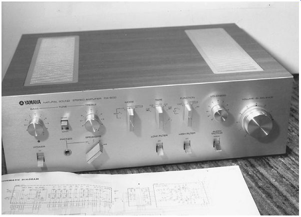
FIG. 18 Check all electrolytic capacitors within the high-powered transistor
stereo amplifier with an ESR meter.
A low rushing noise in the left channel with weak audio can be caused by a power output IC. Check all output transistors for weak sound when they are too warm to touch. Suspect a change in emitter resistors for weak audio. Compare the normal voltage source with that feeding the weak left channel. A bad earphone jack can cause weak and intermittent sound. The weak channel can be caused by a grounded tone or volume control in the left channel. Low volume was noticed in an Onkyo TA2028 model and was caused by bad transistors Q203 and Q203 (2SC1384).
Intermittent stereo channel
Are both channels intermittent? Monitor the audio at the volume control with the external audio amp, and use a speaker tied to the output terminals of the intermittent channel. If the audio is intermittent with the external power amplifier, you know that the defective component is in the audio input circuits. If the audio is normal at the volume control and intermittent at the speaker, you know that the intermittent component is in the audio output circuits. If the sound is intermittent at the volume control, the defective part is in the audio input circuit. You can use the radio circuits or the cassette signals to troubleshoot an intermittent channel (Fig. 19).
If the intermittent component is in the output circuits, use a regular speaker or an external amp as a monitor. Sometimes when a test instrument is touched on one element of a transistor, the sound will return. Check the voltages on the transistors and ICs when there is intermittent sound. Applying coolant and heat to transistors and capacitors can make the part act up. Probe around small components with an insulated tool to find poorly soldered terminals or parts. Pushing up and down on sections of the PC board can cause the chassis to become intermittent. Resolder the intermittent PC board wiring section to locate a badly soldered joint. Don't overlook large blobs of solder on wiring junctions. Check for a worn or broken volume control.
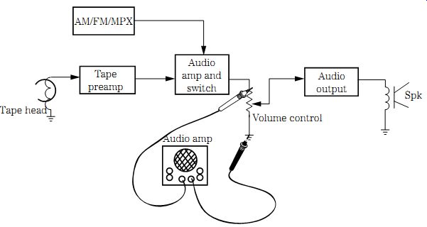
FIG. 19 Start at the volume control with the external audio amp to isolate
half the audio channel in cassette and receiver circuits.
Check low-value coupling capacitors (1 to 10 uF) for intermittent audio. Poor PC board connections and cracked traces can cause intermittent sound. Check for broken traces and PC wiring with an equivalent series resistance (ESR) meter. Do not overlook preset volume or bias controls for intermittent audio. A dirty function switch can cause intermittent sound. A bad voice coil with broken connections to the speaker can cause intermittent audio. Double-check heat sink screws for intermittence and a crackling noise in the speakers. Replace a bad volume control when the audio cuts up and down as the control is rotated. A badly soldered connection on the volume control can result in intermittent sound. Check the speaker relay when one channel is intermittent.
Most intermittence problems within audio output circuits are the result of bad coupling capacitors, AF or driver transistors, and power output transistors or IC components.
Check the driver transistors and soldered terminal connections for an intermittent audio channel. Power output transistors can become overheated and cut the sound in and out.
Double-check all power output terminals for properly soldered joints.
Intermittent audio can result from a defective power output IC. Check the power output IC if it appears quite warm after operating 10 to 25 minutes. Resolder all the IC terminals. Check the sound at the input and output terminals before removing the suspected IC. Double-check the IC mounting screws for a loose mounting, which can cause intermittence and a noisy sound in the speakers. Sometimes the entire audio PC board must be re-soldered for intermittent sound.
Intermittent audio can be caused by an intermittent voltage source feeding the audio circuits. When a certain stage is found to be intermittent, monitor the voltage source to that stage with a DMM. Notice when the sound cuts up and down if the voltage changes at the same time. A change in the voltage source can be caused by a defective voltage or IC regulator. Resolder all the regulator terminals. An intermittent diode or a poorly soldered diode connection in the regulator circuit can cause intermittent audio.
Do not overlook the possibility of a bad protection relay, which can cause intermittent sound applied to the speaker.
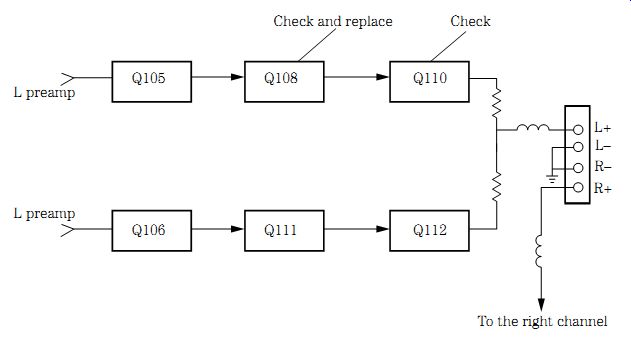
FIG. 20 Do not overlook a leaky driver transistor when there is intermittent
audio and a shorted Q110 and open Q112 output transistor.
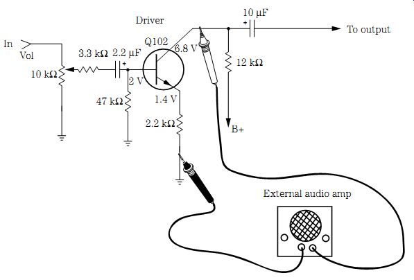
FIG. 21 Go from base to collector terminal with the external audio amp to
locate the noisy channel.
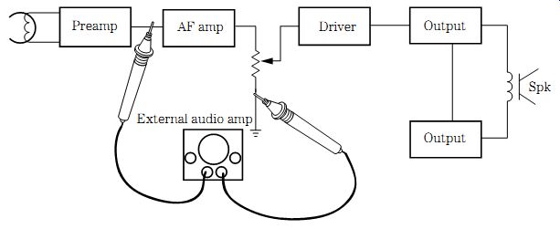
FIG. 22 Keep the volume low on the external audio amp as you try to isolate
the distorted audio stage.
INTERMITTENT LEFT CHANNEL
The left channel in a Radio Shack 200-W amplifier was intermittent after operating for an hour or so. The right channel was normal. An external audio amp was connected to each output transistor, and when the amplifier acted up, the external amp was connected to the base of the next directly coupled transistor. When the external amp was connected to the base terminal of Q110, the audio cut out. Right away the external amp was connected to the base terminal of Q108 and appeared normal.
Replacing power amp Q108 cured the intermittent left channel (Fig. 20).
Noisy left channel
Try to locate the noisy channel by signal tracing with the external amp or scope.
Start at the volume control. If the noise is heard at the volume control, proceed through the input and preamp circuits until the noisy stage is located. If you can eliminate the noise by turning down the volume control, the noise is in the input circuits. Go from base to base of each preamp or AF transistor until the noise can be heard no longer. If the noise is heard on the base terminal and not the collector terminal of a suspected transistor, you have located the noisy stage (Fig. 21).
Most noisy problems are caused by defective transistors, ICs, diodes, or capacitors.
Replace the audio output transistors for a crackling sound after warmup. A popping noise heard in the speaker can be caused by a defective output transistor or IC. No audio and a popping noise can be caused by a hot power IC. A squealing noise may result from a defective electrolytic in the audio circuits. Tighten the heat sink screws when there is intermittent audio and a cracking sound. Static in the sound can be caused by a defective power output IC. Audio buzzing can be caused by a bad zener diode in the power source that feeds the audio channels. Resolder all connections on the power out put IC for a noisy stage. Replace the defective output transistor when there is a low mo tor-boating noise with the volume turned down (Fig. 22).
Replace a 1000- uF electrolytic when there are motoring-boating and chirping noises. A motor-boating sound in the speakers can result from electrolytic coupling capacitors (1 to 10 uF) or larger filter capacitors (470 uF). Open decoupling filter capacitors can cause a chirping noise with a motor-boating sound. You may have to replace more than one filter capacitor when there is a motor-boating sound. Check all filter capacitors with an ESR meter.
An open filter capacitor can cause a squeaking noise in the speaker. A loud whistling noise can result from a bad filter capacitor. Suspect a defective filter capacitor when a loud popping noise is heard with the volume turned down. A bad filter capacitor can cause a high-pitched noise that disappears when the volume is turned up. Check the PC board for loose screws or solder, which can cause excessive hum and a buzzing noise. A bad PC board ground can result in a static-type noise in the speaker. A Yamaha R2000 receiver gave out a noisy and cracking sound. Replace a 4.7-ohm, 1/4-W resistor near the 4700- uF filter capacitor causing the noisy symptom.
NOISY SOUND, ONKYO
After an Onkyo TX-V940 receiver operated for a few hours, a noisy left channel developed. Rotating the volume control clear down had no effect on the noisy audio.
The noisy component was located by signal tracing the audio output circuits with an external audio amp. A noisy driver transistor (Q501) was found in the input circuits.
A bad function switch can cause a hissing sound in one channel. Replace the dual output IC when the left channel is noisy and the right channel has a firing noise after 5 minutes of operation. Replace a defective power switch when there is a constant arcing sound after the unit has been turned on. Sometimes you may find more than one defective component that can cause a noisy sound with the volume turned down, such as a defective 4.7- uF, 25-V electrolytic, silicon diode, or driver transistor.
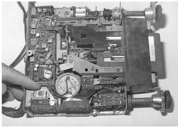
FIG. 23 Look for a small heat sink and defective power stereo IC within an
auto receiver that has distorted sound.
Distorted sound
Although most distorted audio is found within the output circuits, audio distortion can occur in any audio stage. Signal trace the distortion within the stereo amplifier with an external audio amp or with a cassette and scope within the cassette deck. A low distorted channel can be caused by bad audio output transistors, burned bias resistors, and leaky bias diodes. Replace the defective driver transistor for low volume and distortion in the speaker. Always check each bias resistor for correct resistance after finding a leaky or shorted transistor. Check all low-ohm resistors in the audio circuits for a change in resistance. Suspect open or dirty variable bias controls for low distorted sound (Fig. 23).
Replace the audio driver transistor or IC if distortion occurs after warmup. Some times the driver and both output transistors must be replaced to solve a distorted audio problem. Spray coolant on the suspected AF or driver transistor to clear up or make the channel more distorted. Replace both audio output transistors for weak and distorted sound. Suspect a driver transistor when the volume cuts out or becomes weak or distorted. You may find one output transistor open and the other leaky. Quickly check all transistors in the audio circuits with the diode tester of a DMM.
Check for leaky coupling capacitors for a distorted AF or driver stage. Try to adjust the bias control when the left channel becomes distorted at high volume. Check for a change in or open large-load resistors within the driver or AF audio circuits. Remove one end of the suspected resistor, and take an accurate measurement. Do not overlook a dirty or worn function switch for distorted or garbled sound. A distorted left channel might be caused by a defective audio output transformer.
Excessive distortion always occurs in the audio output circuits. Test each power output transistor and IC for extreme distortion. An open coupling capacitor tied to the volume control can cause weak and distorted audio. Go directly to the high-powered output ICs for extreme distortion. Replace the suspected output IC when distortion occurs after warmup. A defective power output IC can cause extreme distortion. Replace the power output IC when extreme distortion is found along with a popping sound.
Replace both output ICs when extreme distortion is found in both channels. Look for something in common with both channels when distortion is found in the left and right output speakers, such as a dual power output IC, improper voltage source, or defective power supply. In high-powered amplifiers, if a positive or negative voltage is missing, extreme distortion results. Replace the defective regulator transistor when distortion occurs after several hours of operation. A weak and distorted channel can be caused by defective IC outputs and a missing negative voltage. A bad voltage regulator can cause garbled audio in the audio stages. Suspect a defective driver IC and voltage regulator when there is distorted audio after warmup.
Check for leaky diodes and dried-up or open electrolytic capacitors within the voltage sources that feed the high-powered transistors. An open 470- uF electrolytic on the 14-V line can cause distortion. Check all electrolytic capacitors within the power supply for distortion with an ESR meter (Fig. 24). When the audio output IC keeps shorting out with extreme distortion, replace all electrolytics in that voltage source. Replace R1904, IC1900, and U1001 for extreme distortion in an RCA CTC159 TV chassis.
High-powered signal path
Often, power output transistors within the power output circuits are directly coupled to one another or with a resistor in between. Notice that the signal path is found at the base of Q101 and that one-half of the Darlington transistor amplifies the audio signal and directly couples to the base terminal of Q103 (Fig. 25). The output audio from the collector of Q103 is fed through a resistor to the base of Q105. Also, the audio signal is fed to the emitter of Q107, with the collector fed through a resistor to the base of Q106.
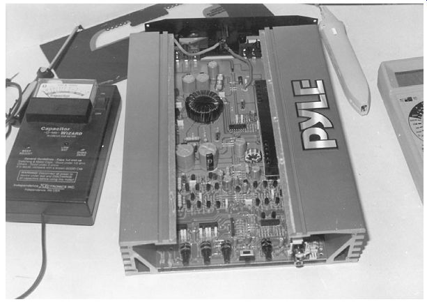
FIG. 24 Check all electrolytics in the output audio circuits with an ESR meter.
Q105, Q106, Q108, and Q109 are in a series push-pull amplifier circuit. Q105 and Q106 operate in a push-pull audio circuit and feed the output signal from the emitter terminals to the base of Q108 and Q109. Again, Q108 and Q109 are in push-pull operation. The high-powered audio output signal is taken from the emitter resistors of both Q108 and Q109 through a coil-resistor network and speaker relay switch.
Check the audio signal at the base of each transistor for audio gain with an external audio amp or scope probe. Notice the gain or loss of each stage. The signal at each base can be compared with the same circuit of the normal channel. A loss of signal or distortion can be signal traced to a defective transistor circuit. When signal or distortion is noted on the base of a transistor, check the preceding circuits. You may find an open driver or leaky AF transistor producing weak and distorted sound.
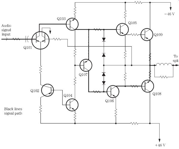
FIG. 25 Follow the audio output signal from base to base of each transistor
through the high powered audio stereo channel.
Checking defective stereo circuits with an external amp
An external audio amp is a very useful test instrument when monitoring audio intermittent, weak sound, noisy circuits, or a dead stereo channel. Always keep the volume on the external amp as low as possible. Plug the defective amplifier into a variable-isolation power transformer. You can go from stage to stage to find the defective component. Then compare the signal at the defective stage with the normal stereo channel. Clip the amplifier ground lead to the common ground on the defective amplifier, and start signal tracing at the volume control. If the noise or distortion can be controlled with the volume control of the defective amplifier, signal trace the audio amp output circuits with the external audio amp.
Hum in the sound
A loud hum in both speakers can be caused by open filter capacitors or broken foil around PC board leads. Check the large filter capacitors if they appear leaky. Suspect a decoupling capacitor when a hum appears after a few minutes of operation.
Shunt these capacitors with the power off so as not to destroy solid-state components. Turn the power on, and listen for a hum in either channel.
Hum in one channel can be caused by a leaky audio output IC. Open electrolytics in the voltage source of the power output IC can cause extreme hum in the audio. Suspect a defective power output IC when there is hum in the speaker when the power switch is turned off.
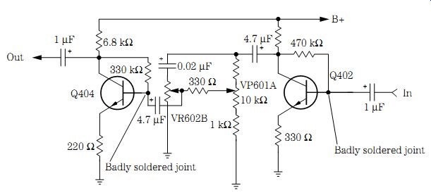
FIG. 26 Resolder all terminals on the driver transistor for a dead channel
and hum in the speaker.
An open volume control can cause intermittent audio and a low hum in the speakers. Low hum can be caused by poorly soldered PC boards. Check for open low-ohm resistors and leaky diodes when there is hum in the speakers. Check for an open resistor tied to the volume control when there is a variable hum noise. Low-level hum can be caused by a leaky diode. A bad relay can cause hum and an intermittent clicking noise in the audio. Red hot resistors in the power output circuits can cause hum in the sound.
Replace resistors R501, R502, R503, and R317 on pins 10 and 12 of IC301 for hum in the sound of a Fisher CA226 receiver amplifier.
Replace a 220- uF, 10-V and a 10- uF, 160-V electrolytic in the voltage source for hum in the sound. Low hum can be caused by a defective electrolytic in the voltage sources. A slight hum can occur with a lower voltage source caused by a large filter capacitor (6800 uF). Replace large filter capacitors when there is hum and a buzzing noise in the sound.
A dead channel with hum in the speaker can result from a badly soldered joint on a driver transistor (Fig. 26). A leaky driver transistor can cause a loud hum in the audio. Replace both output transistors when there is low hum in the left channel. Suspect defective bias resistors in the emitter circuit of the output transistor when hum occurs after the amplifier is on for 5 or 10 minutes.
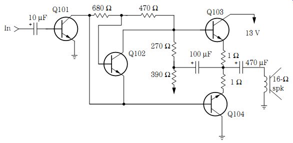
FIG. 27 Early low-priced TVs used small transistors within the stereo output
circuits.
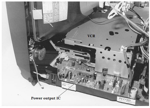
FIG. 28 The audio circuits within a low-priced TV/VCR combo have a dual output
IC.
TV sound circuits
In early stereo and low-priced TV audio circuits, output transistors were found in each stereo channel. The AF driver transistor (Q101) is directly coupled to Q104 and through a low-ohm resistor (680 ohms) to the base of Q102. The sound is directly coupled from the collector of Q102 to the base terminal of Q103. Q103 and Q104 operate in a simple push-pull audio circuit. A low 13-V source feeds the driver and output circuits of Q103 and Q104 (Fig. 27).
A simple power output IC may contain a dual audio output stage. The whole audio circuit may be found in one large IC component. Check the dual output IC when both stages are affected with distortion, intermittent audio, noise, or a dead stereo channel and the other channel is okay. Often, when a dual audio output IC becomes defective, both channels are distorted, weak, or intermittent. Stereo sound within smaller TV screens can employ a dual or single output IC for each channel. Replacing the dual out put IC can solve problems within both output circuits (Fig. 28).
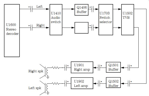
FIG. 29 Block diagram of present-day deluxe TV stereo audio output circuits.
Deluxe TV stereo channels may include a stereo decoder IC, an audio switch, a buffer transistor, a mode switch selector IC, a TVB, audio preamps, and separate high powered output ICs. The stereo audio is developed within the stereo decoder IC and is capacity coupled to an IC audio switch (U1410). A separate buffer transistor is found between the audio switch IC and is capacity coupled to the mode selector switch (U1903). Again, two buffer transistors are capacity coupled to the separate power out put ICs from U1502. An 8- or 16-ohm permanent magnet (PM) speaker is capacity coupled to the left (U1902) and right (U1901) power IC amplifiers (Fig. 29).
A defective stereo decoder (U1710) can cause a dead channel or dead audio in both channels. Check the supply voltage (11.5 V) at pin 1 of U1710 in an RCA CTC167 stereo decoder circuit. Low voltages may indicate that U1710 has become leaky, reducing the supply voltage. The supply voltage may be low from the power source, causing weak and distorted sound. Simply remove terminal 1 from the PC wiring trace with a solder wick and iron. Flick terminal 1 with a small screwdriver or pencil to make sure that the pin terminal is loose. Now measure the supply voltage at the removed pin trace terminal. Suspect a leaky U1710 when the normal voltage returns or the voltage is a volt or two higher.
Go directly to the voltage source in the power supply if the voltage is still extremely low (Fig. 30). A defective U1710 has been known to cause a dead right channel, whereas a defective left Summer channel transistor (Q1703) has resulted in a weak channel. Do not overlook a surface-mounted solid component that has a poorly soldered end connection that ties the voltage circuits together at the IC component.
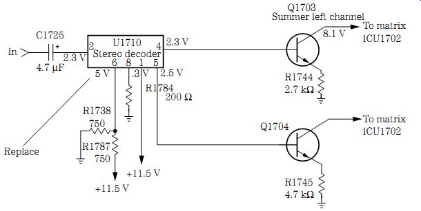
FIG. 30 Leaky stereo decoder (U1710) in an RCA CTC167 chassis caused a weak
stereo out put signal.
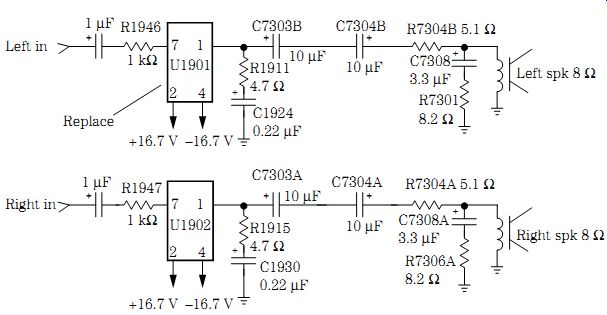
FIG. 31 Notice that a positive and negative voltage are applied to the output
U1901 and U1902 ICs in the latest stereo channels.
TV IC power output components
The latest stereo power output circuits in TV chassis are usually found with IC parts.
A dual-purpose power output IC is found in lower-priced models, whereas more powerful and separate ICs are found in the latest TV sound circuits. The audio input signal is capacity coupled to the input terminal of each separate power output IC.
Likewise, the output terminal is capacity coupled to an 8- or 16-ohm PM speaker. In some high-powered IC circuits, separate positive and negative supply voltages are found (Fig. 31).
Signal trace the weak, intermittent, or distorted signal into and out of the power IC to locate the defective channel. Then signal trace the audio signal into each input terminal. When no schematic is available, apply the signal tracer indicator probe to each terminal until the right one is found. The output terminals can be located by tracing from the defective speaker connection. Now compare the same terminals with the normal audio output IC. Another method is to inject the audio signal into the normal audio output IC to find the input and output terminals and then to check for the same amount of audio at the defective IC.
A defective power output IC can run warm. A defective output IC might cause a noisy and crackling sound. No audio may result from a badly soldered connection or a broken trace wiring. Both audio speakers can be dead when there is a bad dual output IC. Sometimes prodding around on the noisy output IC can make the IC act up or quit.
Replace the defective IC when a frying noise occurs after 5 or 10 minutes of operation.
Suspect poorly soldered joints on the power output IC terminals when the audio cuts out in both channels. The defective power IC can be okay for several minutes, and then shuts off; then only a hum is heard. A popping left channel with distorted sound can be caused by a bad output IC. You may have to replace both power output ICs when distortion is found in both channels.
The dead or distorted audio channel can be caused by missing a positive or negative voltage on the power IC. Check for a defective voltage regulator IC when the audio becomes distorted after warmup. Check for a leaky voltage regulator transistor when improper voltage is fed to the power output IC. An open large filter capacitor can cause distortion in the voltage source and in the power IC circuits.
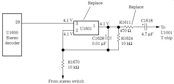
FIG. 32 Distorted sound in an RCA CTC187 TV stereo chassis was caused by a
defective U1601 and R1611 (470 ohms).
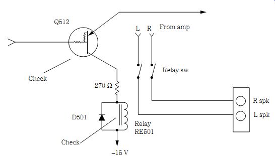
FIG. 33 Check the solenoid driver transistor and solenoid switch for intermittent
sound in the speaker.
NO SOUND, RCA CTC187 CHASSIS
A dead and distorted audio section within an RCA CTC187 TV chassis can be caused by several different audio components. The normal audio was traced, and a defective U1601 IC and R1601 (470-ohm) resistor and an open R1618 (33-kilohm) resistor were found in the 12-V source of the power supply. In another RCA CTC187 chassis, U1601 and Q1001 were found shorted with an open R1627 (200-ohm) resistor in the audio out put circuits. Also check for a leaky C1617 (4.7 uF) within the same chassis (Fig. 32).
Speaker relay problems
A bad relay can cause the sound to cut in and out at low volume. Suspect a bad speaker relay when the volume cuts in and out at any level of audio. A static noise in the speaker with one channel cutting out can be caused by a bad speaker relay.
Check the speaker relay when intermittent audio is found in both speakers. Replace the speaker relay when only one channel is intermittent. Check for bad connections on the relay when the sound cuts in and out. The speaker relay may not energize with a bad voltage regulator IC or transistor (Fig. 33).
Audio protection circuits
When the protection relay will not click on, check for a defective protection IC. A bad zener diode in the voltage source can cause the protection relay to not turn on the speakers. Check for a badly soldered joint on the protection IC when the protection circuit comes on after a few minutes of operation. The speaker may not be activated with a shorted protection IC. Suspect a bad protection IC when the relay will not click on or off. A no-sound symptom can result from a leaky protection IC.
Resolder all connections of a voltage regulator transistor or IC with a clicking protection relay with intermittent audio. Suspect a bad protection IC when there is no audio in either speaker. A bad protection IC will not let the relay click on (Fig. 34 on p. 306).
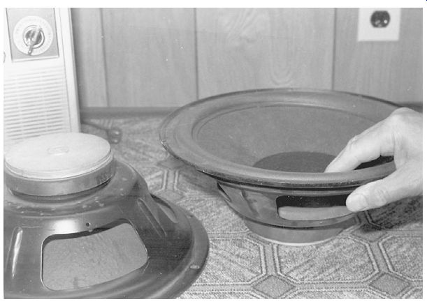
FIG. 35 Push up and down on the large speaker cone to see if the voice coil
is dragging or frozen.
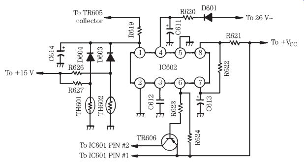
FIG. 34 A bad speaker protection IC (IC602) in the protection circuits can
cause no or intermittent audio.
Large speaker problems
Large audio speakers can become defective as a result of a warped or loose cone. A blatting sound from the speaker may result from a loose voice coil diaphragm. Sharp objects poked into a speaker cone can make a vibrating sound. A frozen speaker cone can be damaged by too much applied volume. A blown speaker voice coil can be caused by too much volume applied to the speakers. Check the speaker by pushing up and down with your fingers to see if the cone rides against the magnet or is frozen and will not move (Fig. 35).
For more amplifier problems and solutions, check Table 1.
==========
Table 1. Servicing stereo sound circuits.
----
Symptom Dead--no sound, Intermittent sound, Weak sound, Distorted sound, Hum in sound, Motor boating in sound, Output transistors a run red hot
-------
Location:
Volume control
Output circuits
Input or output
Input or output
Output stage
Filter capacitor
Low-level hum
Audio output
Low-voltage power supply
Output stage
-------------
Repair:
Signal trace the audio at the volume control to determine if the problem is in the output circuits.
Measure the voltage across the main filter capacitor. Check the voltage on the output transistor or IC. If the fuse is blown, suspect a leaky output transistor or IC. Signal trace the volume control to the base of each transistor with a scope or external amp.
Monitor intermittent audio at the volume control to determine if the problem is in the input or output stage. Monitor at the speakers and on the base of the second AF or driver transistor. Monitor at the input and output of the suspected stereo output IC. Look for an intermittent coupling capacitor and burned bias resistors, diodes, and transistors.
If the cassette player sound is weak, check the tape heads. Clean with alcohol and a cloth. Check the weak channel against the normal stereo channel to see what stage the problem is in. Go from one side of the coupling electrolytic capacitor to the other for weak audio. Check the signal from base to base of each transistor. Check the input signal and output of the suspected IC. Weak sound is caused by open coupling capacitors, bias resistors, diodes, and transistors.
Clean the tape heads. Check the input and output of the power IC for
distortion with an external amp. Check each transistor for openness or leakage with in-circuit tests. Remove the transistors and diodes, and check them out of circuit. Check the audio output bias resistors for correct values. Check the bias diodes for leakage. Make sure the voltage source is proper and both the positive and negative sources are equal.
Check the distortion at a given point in the circuit and compare it to the normal channel. If both channels are distorted, suspect a common IC or improper supply voltage. Distortion is caused by open transistors, ICs, bias resistors, and bias diodes, and improper voltage. Remember, in directly coupled circuits, an open or leaky transistor down the line can affect all transistors in the stereo lineup.
Shunt each filter capacitor with a good one. Shut down the chassis to shunt the capacitor. Discharge each capacitor after shunting each one in circuit.
Check and shunt each decoupling capacitor.
Check for an increase in resistance at the base terminal.
Check the input cables and wires.
Replace the audio output or ICs.
Shunt all electrolytic capacitors in the power supply.
Check for open or leaky driver transistors.
Check the bias diodes and resistors.
Check for excessively high voltage source.
Check for either a positive or negative voltage source that is missing.
============