|
|
Introduction
The purpose of this booklet is to introduce the reader to the fundamentals of vacuum tubes and their use in audio preamplifiers and power amplifiers. Interest in vacuum tube audio equipment by both audio manufacturers and audiophiles has greatly increased during the last several years. This increased interest has had two effects. Many new tube amplifiers have been introduced by both existing and new companies. In addition, much has been written to explain the resurgence of the “obsolete” technology of vacuum tubes. The merits of tube versus transistor sound have been heatedly debated. Sadly, many of these discussions have contributed little to an understanding of vacuum tube audio and the unique benefits that vacuum tube amplifiers offer the listener, and instead have only made the issues more confusing. This booklet, and the brief, factual discussions of vacuum tubes and vacuum tube audio that it contains, is intended as a first step in overcoming this confusion.
Vacuum Tubes: Diodes, Triodes, and Pentodes
The simplest type of vacuum tube is the diode (Fig. 5). Although vacuum tube diodes are rarely used in modern audio amplifiers, an understanding of how they work will make it easier to explain how triodes and pentodes function.
The name “vacuum tube” is not very revealing of how these devices operate. True, the inside of all triodes and pentodes, and most diodes, is (or should be) a vacuum. A much more instructive name is the British “thermionic valve.” In the diode of Fig. 5, the inner electrode, called the cathode, is heated to a temperature of about 10000 Kelvin (about 13000 Fahrenheit) by a tungsten alloy wire situated along the inside wall of the cathode. When a current is passed through this wire, called the heater, the cathode (which is electrically insulated from the heater) heats up. The surface of the cathode is treated with a material which freely emits electrons when heated. The emission of electrons from a heated metal or metal oxide (thermionic emission) is called the Edison effect. The number of electrons emitted from a given area of the cathode’s surface depends on the temperature of the cathode: the hotter the cathode, the more electrons are emitted. Of course, the thermal stresses on the heater and cathode also increase as their temperatures are increased. Many years of research have gone into developing coatings for the heater to increase its ability to heat up the cathode, and coatings for the cathode to increase its ability to emit electrons at reduced temperatures which will prolong the life of the tube.
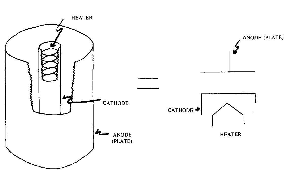
Fig. 5. Vacuum tube diode. Nore its parts: ANODE (PLATE); CATHODE; HEATER
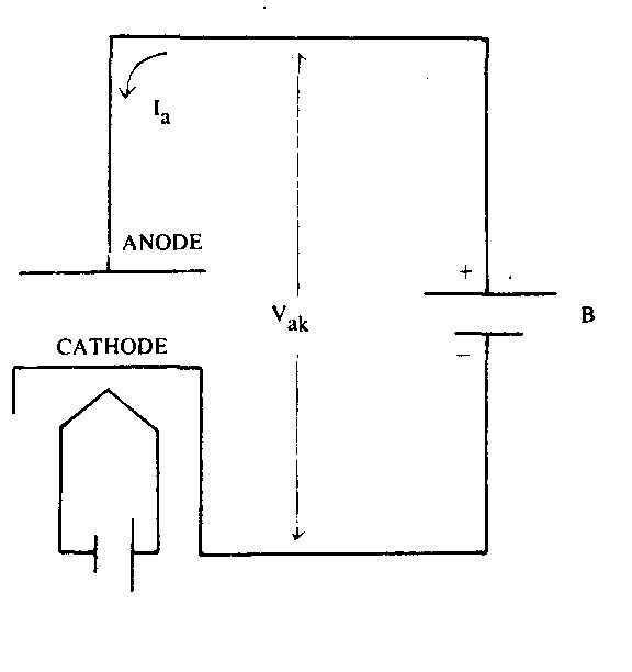
Fig. 6. A simple diode circuit.
Now let’s consider what happens inside the diode when the heater is first turned on, but the cathode and the outer electrode, the anode (also called the plate), are not connected to any electrical circuit. The cathode begins to emit electrons, negatively charged particles. The first electrons to be emitted from the cathode encounter only the vacuum of empty space around the cathode, and some reach the anode. This is not the case for electrons emitted later. The early electrons form a cloud of negatively charged particles around the cathode, called the space charge. This cloud grows and begins to repel the electrons which the hot cathode is still trying to emit. After a while an equilibrium condition is reached, and no further electrons can be emitted from the cathode.
So far, this isn’t very useful behavior from a circuit designer’s viewpoint. Power is being expended to heat the cathode, but the electrons emitted by the cathode are repelled by each other in the cloud of charged particles which forms around the cathode, and only a few electrons reach the anode.
Now suppose that the cathode and anode are placed in the circuit shown in Fig. 6. The battery B maintains a voltage V_ak between the anode and the cathode. This in turn produces an electric field between the diode’s anode and cathode which will affect the motion of the electrons emitted by the cathode. When the anode is at a positive voltage with respect to the cathode, the electric field causes the electrons to accelerate towards the anode. In this state the diode can conduct a current. No longer do all the electrons emitted by the cathode remain in the space charge region, the electric field removes some electrons by accelerating them towards the anode. This allows additional electrons to be emitted from the cathode. An equilibrium condition will be reached in which the number of electrons removed by the electric field will be equal to the number of additional electrons the cathode can emit into the electron cloud. In Fig. 6 a complete electrical circuit exists: electrons emitted by the cathode and accelerated by the electric field to the anode proceed from there back to the cathode via the battery B. These electrons constitute the circuit’s electrical current I_a Because of a convention introduced by Benjamin Franklin (who believed that it was positive charges which circulated in an electric circuit, whereas in fact it is the negatively charged electrons which are responsible for electric currents), the direction of the current I_a is taken to be the reverse of the direction of the electrons’ motion.
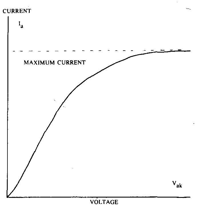
Fig. 7. Diode saturation anode current versus anode to cathode voltage.
Note: CURRENT; MAXIMUM CURRENT; HEATER
The number of electrons which are accelerated to the anode (and therefore the magnitude of the electric current I_a) in a given time interval depends on the strength of the electric field within the diode. For a given spacing between the anode and cathode, the electric field strength in turn depends on the voltage V_ak between the anode and cathode. As this voltage is made greater, the strength of the electric field increases. This increases the acceleration of the electrons, so that more of them can reach the anode in a given time interval. More electrons per second circulate from cathode to anode and back to cathode, so the current I_a is increased. As the voltage V_ak is made very great, a maximum current is finally reached (see Fig. 7). At this point all the electrons emitted by the cathode are accelerated towards the anode, and there is no space charge. The maximum current which the diode can conduct is limited by the number of electrons which the cathode can emit. As was mentioned above, the electron emission characteristics of the cathode are determined by its composition and temperature.
Now suppose that the battery B is connected the other way around in Fig. 6, so that the anode is at a negative voltage with respect to the cathode. In this case the electric field points the other way, causing the electrons to be accelerated back towards the cathode, and not towards the anode. The result is that once again no electrons pass from the cathode to the anode, so the current I_a is zero: the diode is non-conducting in this state. Thus we have shown how a vacuum tube diode can function as a rectifier (a device which conducts a current only in one direction).
The vacuum tube diode is not useful as an amplifying device. The current T conducted by the diode depends only on the anode to cathode voltage V_ak and the cathode temperature. There is no way to make a small external voltage or current control the current I_a and therefore allow the diode to function as an amplifier.
This is corrected in the triode (Fig. 8). The triode is basically a vacuum tube diode with one additional electrode, called the control grid, or sometimes just the grid. As illustrated in Fig. 8, the control grid is a spiral of wire, located between the cathode and plate, and electrically insulated from these other two electrodes. The addition of the control grid makes the triode a much more versatile device than the diode, and allows it to function as an amplifier.
First let us consider how the circuit of Fig. 9 works. This circuit is exactly like the one in Fig. 6, except the diode has been replaced with a triode, and there is a variable voltage source connected between the control grid and cathode of the triode. With the voltage source temporarily disconnected from the control grid, the tube will act like a diode. For a fixed cathode temperature and plate to cathode voltage V_ak, the current through the triode is also fixed.
Now suppose that the variable voltage source is reconnected to the control grid, and the control grid to cathode voltage V_gk is set to some moderate positive value (say, a few volts). The control grid is not a solid metal electrode, but is instead an open wire spiral, so that it does not physically interfere with the motion of the electrons from the cathode to the plate. When the control grid is connected to a voltage source, however, it creates an additional electric field within the triode which can affect the motion of the electrons. When V_gk is positive, the control grid does nothing to inhibit the stream of electrons emitted by the cathode. Some in fact are intercepted by the control grid, so in this case there is a current through the control grid circuit ‘g (cathode to control grid and back to the cathode via the variable voltage source) in addition to the plate current I_a
Now suppose that the grid to cathode voltage V_gk is slowly reduced. The control grid then begins to have a greater effect on the electric field in the vicinity of the cathode. When V_gk is made negative, the control grid begins to inhibit the flow of electrons from cathode to plate. The electric field due to the control grid opposes the greater electric field due to the plate to cathode voltage V_ak. The more negative V_gk is made, the greater is the effect of the control grid on the flow of the electrons from the cathode to the plate, and the less the plate current I_a becomes. In addition, the grid circuit current 1 is greatly reduced, just as I_a dropped to zero for the diode when the plate to cathode voltage was made negative.
This behavior explains why the triode’s additional electrode is called the control grid. The control grid to cathode voltage V_gk controls the plate current I_a. When V_gk is negative, a small change in its value can produce a large change in the plate current. As V_gk is made more and more positive, the control grid has less effect on I_a. If V_gk is made sufficiently positive, the control grid ceases to control the plate current, and the tube then functions exactly like a diode. In most triode amplifier circuits, the grid to cathode voltage is always negative.
The circuit of Fig. 9 may be used to make a series of measurements of the triode’s electrical behavior, and from this a graph could be generated showing the relationship between the plate current 1 plate to cathode voltage V_ak , and control grid to cathode voltage V_gk. This graph would display the characteristic curves of the particular triode. There are several different but equivalent ways in which the information could be graphed to form a set of characteristic curves. The most common is the plate characteristics curves, shown in Fig. 10. These curves show the relationship between V_ak and I_a for a number of different values of V_gk. The plate characteristics curves are very useful in explaining how a triode amplifier stage works.

Fig. 8. Vacuum tube diode.

Fig. 9. A simple triode circuit.

Fig. 10. Triode characteristic curves.
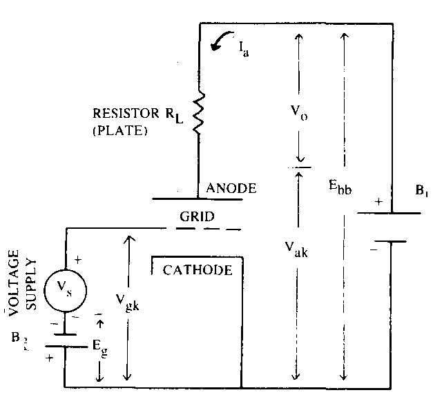
Fig. 11 Triode amplifier circuit.
Fig. 11 illustrates a simple triode amplifier stage. Instead of being connected directly to the main power supply (battery B of voltage Ebb), the plate is now connected to a resistor RL. For simplicity the heater is no longer illustrated. It is assumed that the heater is connected to an appropriate power supply. The variable control grid voltage supply of Fig. 9 has been replaced by a second battery B of voltage Eg in series with a signal generator with output voltage V
First let us consider the state of the triode when the signal generator’s output voltage V is zero. In this case the net control grid to cathode voltage V_gk is determined solely by battery BV_gk o = — Eg (the voltage is negative because the positive end of B is connected to the cathode). This biases the triode to a convenient (and unique, for a given value of Ebb and RjJ quiescent operating point, marked Q in Fig. 12. The plate to cathode voltage V_ak o is not equal to the plate supply voltage Ebb because there is a current I_ao through the triode, and this current produces a voltage drop of magnitude IaoRL. The sum of the voltages dropped across the triode and the load resistor RL must equal the supply voltage, so V_ak o = Ebb — IaoRL.
Now suppose that the signal generator is turned on, and set to deliver a very low frequency triangular voltage V At first the voltage V slowly increases, which has the effect of slowly decreasing the control grid to cathode voltage: V_gk = V - Eb. From the description above the affect of V_gk on the plate current I_a we remember that as V_gk is made less negative, the plate current I_a increases. This in turn increases the voltage drop across the load resistor RL, which means that V_ak must decrease. As V slowly increases to its maximum positive value, the voltage across RL slowly increases, while V_ak slowly decreases, such that the sum of these two voltages remains equal to Ebb. As V decreases from its maximum value back to zero, the process is reversed, until when V = 0 again, I_a = I_ao and V_ak = V_ak o. As V becomes increasingly negative, I_a continues to decrease to values less than the quiescent value I_ao This means that less and less voltage is dropped across RL, 50 V_ak increases to greater than its quiescent value V_ak o. Finally, as V again returns to zero at the end of one cycle of the triangle wave, the values of V_ak , V_gk and I_a revert back to their quiescent values.
The instantaneous values of V_ak , V_gk and I_a can be plotted on the plate characteristics curves of Fig. 12. When this is done, a straight line is formed. This line is called the loadline, and its slope depends on the value of the load resistor RL. When the value of RL is very large, the loadline is nearly horizontal. When the input signal is applied to such an amplifier stage, the changing value of V (and therefore the changing voltage dropped across RL) will produce only a small change in the plate current 1 If the value of RL were made in finitely large, the loadline would be horizontal. A horizontal loadline is illustrated in Fig. 13. In this case, a given small change in the grid to cathode voltage A V_gk produces the greatest possible change in the plate to cathode voltage AV_ak . I_a does not change. The ratio A V_ak / A V_gk is called the amplification factor j of the tube. A simple tube amplifier stage can not have a voltage amplification (voltage gain) of greater than i. Usually the value of the load resistor RL is not great enough to produce a nearly horizontal loadline, and the voltage gain will be less than the amplification factor u.
When RL is made equal to zero, the loadline becomes vertical. A vertical loadline is also illustrated in Fig. 13. Now a given small change in the grid to cathode voltage A V_gk produces the maximum possible change A I_a in the plate current. In this case V_ak does not change. The ration delta_I_a/delta_V_gk is called the mutual conductance (or transconductance) gm of the tube. The ratio /g, is called the plate resistance rp of the tube, and is equal to the slope of the plate characteristics curves.
The quantities , u, gm, and rp are often misleadingly referred to as tube (or valve) constants. The term is misleading because they are not constant. This is most evident for rp. The characteristic curves in Fig. 13 are obviously not straight lines, so the slope of the line (and therefore rp) depends on the values of V_gk, V_ak and I_a The values of both u and g also depend on he instantaneous operating point of the tube. It is this variation in tube constants which produces amplifier distortion. It is the task of the circuit designer to properly choose the tube type, quiescent operating point, load resistor, and so forth to make the amplifier as distortion-free as possible. The amplification factor t depends primarily on the physical construction of the tube: the spacing between the grid and cathode, and the spacing between the helical wound wires of the grid. The value of the plate resistance rp depends more on the instantaneous value of the plate current I_a than on the instantaneous value of the plate to cathode voltage V_ak . This means that the linearity of the amplifier can be maximized by minimizing delta_I_a for a given output voltage. This can be achieved by making RL large, which has the added benefit of increasing the voltage gain. However, RL should not be made too large for a given plate supply voltage Ebb, or the loadline will fall in the shaded region shown in Fig. 13. The characteristic curves are most strongly curved in this region of very low plate current, so the value of rp becomes very sensitive to the instantaneous value of I_a voltage which would appear if there were no local feedback. The net distortion in the amplifier stage ‘s output voltage is thereby reduced. The local feedback produced by the signal current through the cathode resistor Rk lowers the amplifier’s distortion.
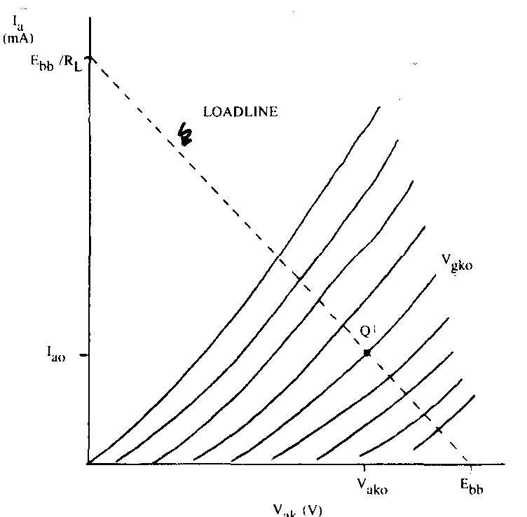
Fig. 12. The loadline.
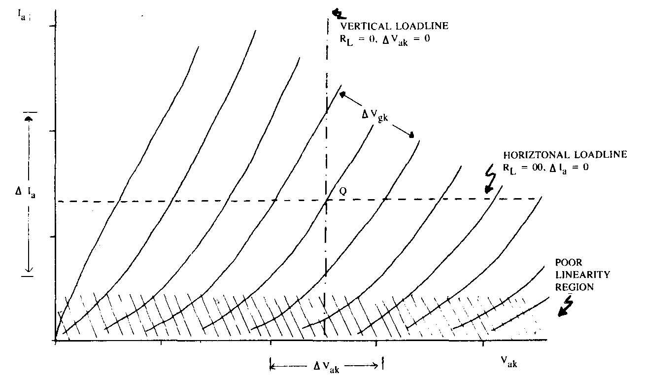
Fig. 13. Tube constants and triode plate characteristics curves.
Another common and useful type of amplifier stage is the cathode follower (also called a common plate amplifier stage). A simplified schematic of a cathode follower stage is shown in Figure 15. In a cathode follower there is no plate load resistor. Instead, the output voltage is developed across the cathode resistor Rk. The value of this resistor is usually much greater than would be used in a common cathode amplifier stage. This provides a great deal of negative feedback (the cathode follower is sometimes said to have 100% negative feedback), but the voltage gain of the cathode follower is always less than one. Although the cathode follower is not useful as a voltage amplifier, it finds wide application as a buffer amplifier. The circuit’s large amount of local negative feedback has three beneficial effects: it makes the amplifier more linear, it increases its input impedance, and it lowers its output impedance.
At DC and low audio frequencies, the intrinsic input impedance of most vacuum tube amplifier stages is very high. When the grid is biased sufficiently negative to the cathode, almost no grid current is drawn by the tube, so very little signal current is drawn from the previous amplifier stage. This is not always true at higher frequencies, however. The plate, cathode, and the various grids of a vacuum tube are basically air spaced metal plates, and as such form capacitors which affect the performance of vacuum tube amplifier stages. The impedance of a capacitor drops with increasing frequency. To maintain a given signal voltage across a capacitor, twice as much current must be forced through the capacitor at 2 kHz as at 1 kHz. The interelectrode capacitances of the vacuum tube will combine with other circuit elements to form low pass filters, which will cause the frequency response of the amplifier to roll off a high frequencies.
The input capacitance of a common cathode amplifier stage can be as high as 150 picofarads or more. The input impedance of such a stage would be quite low at high frequencies, and the frequency response of the complete amplifier containing this stage would probably begin to roll off at 20 kHz or below. If the complete amplifier contained two stages with similar, comparatively low roll-off frequencies, its performance at high frequencies would probably be quite poor. If the complete amplifier did not use overall negative feedback, then the response of the complete amplifier would be noticeably rolled-off at high audio frequencies. If the amplifier did use overall negative feedback, the frequency response of the amplifier with feed back might be acceptable, but there are still several problems with the design. The amount of negative feedback around the amplifier decreases at high audio frequencies when the frequency response of the individual stages begins to roll off, so the amplifier’s linearity at high audio frequencies is poorer than at lower frequencies. The amplifier may also be unstable, causing it to overshoot or ring on fast changing signal waveforms, or perhaps even oscillate. To ensure the stability of a feedback amplifier, the frequency response of the individual amplifier stages must be carefully tailored so that the amplifier’s overall frequency response (before feedback is applied) does not fall off too abruptly at high frequencies. The high input impedance of the cathode follower allows such tailoring.
The input capacitance of a cathode follower can be as low as a few picofarads. Its input impedance therefore remains high at high frequencies. It does not load down the preceding amplifier stage, so its frequency response can remain flat to a higher frequency. In addition, the output impedance of a cathode follower will be much lower than the output impedance of a common cathode amplifier using the same type of tube. This means that the gain of the stage is little affected by changes in its output loading. In the discussion of the common cathode amplifier stage, it was noted that when the load resistance RL was made much greater than the plate resistance rp that the amplifier’s gain became constant (approximately equal to the amplification factor u (Greek mu)). The cathode follower circuit exhibits this same behavior. When the effective load impedance (consisting of the cathode resistor Rk in parallel with the input impedance of any following amplifier stages or networks) is much greater than the effective plate resistance rp’, the voltage gain reaches a constant value equal to the effective amplification factor u (mu). Because rp’ is so much lower than rp the gain of the cathode follower is much less influenced by changes in the load it must drive than is a common cathode amplifier stage. Therefore the cathode follower is a very effective buffer amplifier: its low effective plate resistance allows it to drive relatively low impedance loads with good linearity without a loss of voltage gain, while its high input impedance prevents the frequency response of the previous stage from prematurely rolling off.
Fig. 16 shows a typical complete low level amplifier for a preamplifier, such as would be used for a moving magnet cartridge. The amplifier consists of three stages: two cascaded common cathode amplifier stages followed by a cathode follower stage. The first two stages provide the necessary voltage gain, while the cathode follower drives the overall negative feedback network and any other external load (volume controls, tape recorders, etc.) The feedback network consists of R0, R1, C1 and C2 which controls the voltage gain of the complete amplifier to provide the necessary RIAA equalization. This is discussed in more detail in a later section. The capacitor Cc couples the first stage to the second for audio frequencies.
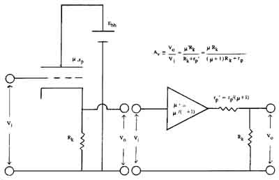
Fig. 15. Cathode follower amplifier stage and circuit model.

Fig. 16. Complete low level amplifier.
Another variety of vacuum tube is the pentode. Its internal construction is similar to that of the triode, but an additional two wire helix grids are introduced between the control grid and the plate. The additional grid nearest the control grid is called the screen grid, and is usually connected to a power supply of some sort. The grid nearest the plate is called the suppressor grid, and is usually connected to the cathode of the tube, either in the external circuit or within the envelope of the vacuum tube.
These additional grids affect the electric fields within the tube in a rather complicated manner, but their effect is to produce a tube with a much higher amplification factor ,u , and often a proportionally higher plate resistance rp. This means that although an amplifier stage employing a pentode with an amplification factor of 1000 is capable of giving a voltage gain of nearly 1000, in practice the gain is likely to be much less. The voltage gain of an amplifier stage approaches the amplification factor p of the tube when the load resistance RL is made much larger than the tube’s plate resistance rp. Because the value of rp is very large for most pentodes, the value of RL is not likely to be large compared with rp, so the gain will be considerably less then p. A typical amplifier stage using a triode with an amplification factor of 100 might have a voltage gain of 70, while a typical amplifier stage employing a pentode with an amplification factor of 1000 might have a voltage gain of 200 or less. In some circuits this extra factor of three in gain may be useful, but the vast majority of voltage gain stages (not power output stages) in tube amplifiers use triodes.
Pentodes offer improved performance over triodes for voltage amplifier applications in one other area: input capacitance. The pentode’s screen grid acts as a shield between the tube’s output (at the plate) and its input (at the grid). The increased isolation between the plate and grid lowers the tube’s effective input capacitance. For a given gain, the input capacitance of a pentode amplifier can be much lower than for an equivalent triode amplifier. While this can be extremely important in amplifiers designed to operated at radio frequencies, it usually is not significant at audio frequencies. More important is that a pentode amplifier will usually exhibit more tube induced noise than an equivalent triode amplifier. For this reason, and because of the additional power supply circuitry necessitated by the pentode‘s screen grid, pentodes are little used in audio amplifiers except in output stages. Pentodes or beam power tetrodes (a similar type of tube) are very commonly used in the output stage of power amplifiers because they offer much greater efficiency than triodes.
== ==
This article is part of Understanding Tube Electronics (adapted from New York Audio Labs 1984 booklet, by Harvey Rosenberg)
ALSO SEE: The State of Audio Technology; Tubes Versus Transistors -- Is There an Audible Difference?
== == ==