MANY OF THE PARAMETERS of the specifications so far investigated are applicable also to ancillary items of hi-fi equipment . For example, the input sensitivity of a preamplifier, matrix or CD4 decoder is measured and expressed in exactly the same way at the input sensitivity of a complete amplifier though, of course, the output reference is different. The same applies to the S/N ratio.
For the correct interfacing of one item to another the output and input parameters generally need to be known. We have already seen something of this with respect to the pickup/amplifier and amplifier/loudspeaker. Interface problems can also arise with respect to the connection of a preamplifier to a power amplifier, to a decoder or graphic tone control unit between a pre-amplifier and a power amplifier, tuner to main amplifier or preamplifier, headphones to main amplifier, tape machine or tuner, etc. These sort of things will also be looked at in this section.
Hi-Fi Receiver (Tuner-Amplifier)
So far we have not referred specifically to the parameters of a hi-fi receiver or tuner-amplifier as it is sometimes called. The reason is that the parameters of the tuner section are precisely the same as those for a separate tuner and, similarly, the parameters of the amplifier section are precisely the same as those for a separate amplifier. Thus, if you are contemplating the purchase of a hi-fi receiver you can safely use as comparisons the parameters given under tuners and amplifiers.
Some hi-fi amplifiers and receivers, although being of 'integrated design' are arranged so that the preamplifier and power amplifier sections can be operated independently. Sometimes there are a couple of links connecting the two sections or a switch.
With the links removed or the switch set to 'off' , the preamplifier section is disconnected from the power amplifier section. It then becomes possible to take the output of the preamplifier control section to the input of, say, a matrix decoder or graphic tone control unit (equalizer) and the output of the decoder or equalizer back to the input of the power amplifier.
In the case of the decoder, the other two outputs would be connected to a second stereo power amplifier for driving the two rear loudspeakers, as shown at (a) in Fig. 7. 1. Fig. 7.1. (b) shows how a graphic equalizer would be connected.
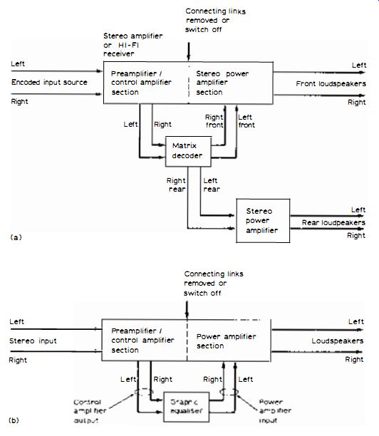
Fig. 7.1: Method of connecting matrix decoder (a) and graphic equalizer
(b) to amplifier or receiver where the preamplifier/ control amplifier
section can be disconnected from the power amplifier section by a switch
or removing a couple of links. Such an amplifier or receiver is equipped
with preamplifier/ control amplifier output sockets and power amplifier
input sockets for the left and right channels. The diagram also reveals
the connecting interfaces (see text) .
Output/Input Matching
For those interconnections to work correctly, the output and input parameters must have a reasonable match. The input sensitivity of the power amplifier section is commonly around 1 V r.m.s. at a fairly high impedance.
Thus for full drive the decoder or equalizer must be capable of delivering, at least, this sort of output voltage.
Similarly, the input sensitivity of the decoder or equalizer must be capable of accepting the output signal level of the preamplifier/control amplifier section without running into input overload.
Input and output impedances are generally less of a problem. However, for the best results and the least likelihood of early treble roll-off due to the capacitance of the interconnecting screened leads, it is desirable for the output impedance to be lower than the input impedance.
For example, a tuner with 100-ohm or so output impedance feeding into a 50 k-ohm amplifier input impedance is a good arrangement. To some extent the same applies to the output impedance of, say, a matrix decoder and the input impedance of a power amplifier. It is not a good thing for the input impedance to be less than the output impedance.
Matrix Decoder
It is also possible to interface a matrix decoder or graphic equalizer across the record/replay tape circuits of a hi-fi amplifier or receiver. When the tape monitor switch lies in the 'on' position a disconnection occurs between the preamplifier and power amplifier sections . Thus by using the recording outputs to feed the ancillary equipment and the output of the ancillary equipment to feed back into tape monitor similar conditions to those shown in Fig. 7.1 are obtained. The scheme is illustrated in Fig. 7.2.
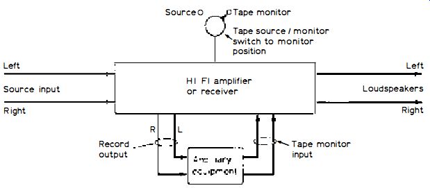
Fig. 7.2: Showing how the tape circuits can be used to interface ancillary
equipment.
With this arrangement the tone controlling, filtering, etc. usually occurs after the ancillary equipment. With the scheme shown in Fig . 7.1 it occurs before the ancillary equipment.
This arrangement is sometimes better than the former one, but it does, of course, tie up the tape circuit. Some amplifiers and receivers, however, are now equipped with two tape circuits and switched monitoring on each, so you could use one circuit for a tape machine and the other for ancillary equipment interfacing.
It will be appreciated, of course, that when the switch is back in the source position the ancillary equipment is bypassed. When the former arrangement is used the tone controlling, filtering, etc. occurs in front of the ancillary equipment; but when the tape circuits are used it usually occurs (on replay) after the ancillary equipment.
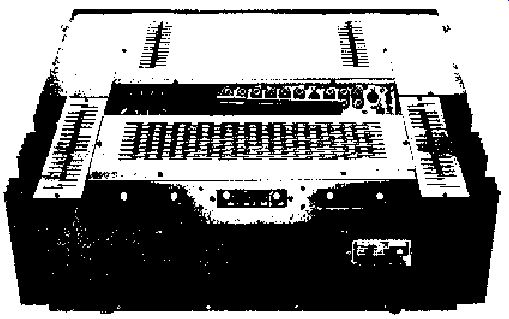
Fig. 7.3: Showing the socketry at the rear of a Rotel receiver, Model
RX-1603.
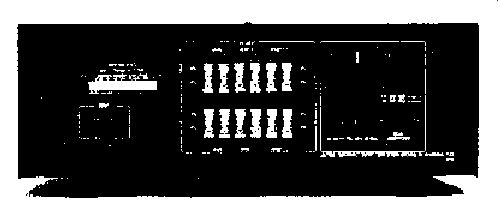
Fig. 7.4: The sockets ( 'phono' type' ) at the rear of a power amplifier
- also showing the loudspeaker terminals.
Tape Circuit Interface
An advantage of using the tape circuits is that the nominal level of signal at the ancillary equipment interfaces is generally less than that when the equipment is introduced between the preamplifier/control amplifier and main power amplifier sections. For example, the tape recording signal may be round 200mV and the tape monitor input sensitivity of a similar value at the 'phono' type sockets. This lower level can be more compatible with the input and output parameters of the ancillary equipment.
You should be aware of DIN socket problems, though; the recording output from the DIN socket is commonly fed through · a high resistance to provide a so-called constant current characteristic to the DIN recording input of the tape machine, the signal voltage thus being dependent on the machine's input impedance.
By using the DIN socket , therefore, you may find that there is insufficient signal fully to drive the ancillary equipment. It is unlikely that you will encounter problems at the monitor input because the DIN socket input sensitivity is the same as, or close to, that of the 'phono' type socket input sensitivity.
Separate Control and Power Amplifier Units
Although most hi-fi amplifiers combine the control and power amplifier sections in a common housing (as , of course, receivers), these being known as integrated amplifiers, amplifiers are still available with separate control and power amplifier units.
The parameters of these are measured and expressed in the same way as integrated amplifiers, but each unit is measured and expressed separately. For example, input sensitivities, overload margins and S/N ratios of the control amplifier are referred to the rated output voltage, while the input sensitivity, overload margin and S/N ratio of the power amplifier are referred to the rated power.
Interfacing of these units raises no problems because they are designed specifically to partner each other. Problems may arise, however, when one make and design of control amplifier is connected to a different make of power amplifier. In this case the output voltage of the control amplifier may be too little or too much for the power amplifier.
Less well known is the fact that the impulse characteristics of the system overall can suffer due to an imprudent partnership even though the interfacing voltage and impedance are compatible.
Transient Intermodulation Distortion
One aspect of this is that for the least possibility of transient intermodulation distortion (TID) - see Section 8 - the designer needs to ensure that the impulse nature of the signal delivered by the control amplifier can be adequately 'digested' by the power amplifier.
This means that he has to arrange for the upper-frequency roll-off of the control amplifier to suit the slewing rate and negative feedback characteristics of the power amplifier. Clearly, then, if a control amplifier with a non-optimized treble-roll-off is used with a power amplifier there is the possibility that TID may occur on certain types of input signal . Conversely, of course, there is also the possibility that the transient (music 'attack') performance of the combination will suffer unduly as the result of a too early treble roll-off. The upper-frequency bandlimiting may be applied at the input of the power amplifier or at the output of the control amplifier.
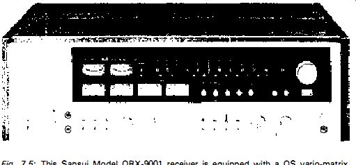
Fig. 7-5: This Sansui Model QRX-901 receiver is equipped with a QS vario-matrix
decoder in addition to decoding facilities for SQ matrix and CD-4 carrier
decoding. It also has a Dolby full processor which can be used as an independent
unit. Four 60W power amplifiers, each channel having logarithmically-calibrated
meters for power monitoring, al low quadraphonic reproduction from virtually
any source, including 'surround sound' from ordinary two-channel stereo
sources.
It is certainly an invalid test to evaluate subjectively the relative performances of control amplifiers by way of a common power amplifier unless one can be assured that the impulse characteristics are fully compatible in all combinations . The same applies , of course, to the subjective evaluation of power amplifiers fed from a common control amplifier . It will now be instructive to look at the parameters of some of the other ancillary items associated with the hi-fi system, starting with the f. m. aerial . Aerials for FM The FM aerial should really be regarded as a part of the front-end of the FM tuner section. It is in fact a tuned circuit which is coupled to the front-end through a feeder cable.
Most FM aerials destined for the UK are designed with a terminal impedance round 75-ohm. Those manufactured for the Continent of Europe have an impedance round 240 ohm, while most of those used in American countries have a terminal impedance more closely related to 300 ohm.
The terminal impedance is established by the overall design of the aerial, including folding the dipole when a reflector and a director or directors are employed, because these tend to reduce the impedance of a dipole, while folding it steps up the terminal impedance again.
Impedance of Feeder
For optimum signal transfer from the aerial to the FM tuner the feeder cable or 'downlead' should have an impedance which matches the terminal impedance of the aerial. This is called the cable's characteristic impedance.
Feeder for 75-ohm aerials is called coaxial cable, while that for 240- and 300 ohm aerials is called twin feeder.
It is also necessary for the aerial input impedance of the tuner to match the characteristic impedance of the feeder. Most FM tuners and receivers are nowadays equipped with inputs for both 75-ohm coaxial cable and 240/300 ohm twin feeder. However, if you are unlucky and your tuner has an input only for 240/300 ohm feeder, you can still connect coaxial cable to it by joining the inner conductor of the cable to one terminal (leaving the other vacant) and the outer braid to an earth terminal or chassis point, as shown at (a) in Fig. 7.6.
The alternative, and sometimes better way, is to interpose a low-loss matching transformer (called a 'balun') between the 75-ohm coaxial cable and the 240/300-ohm aerial input , as shown at (b) . Attenuation of Feeder Assuming a correct impedance match, the amount of signal lost during its travel from the aerial to the tuner depends essentially on the attenuation of the feeder. This is expressed as so many dB per given length and frequency--the longer the cable and the higher the signal frequency the ·greater the attenuation.
Poor quality cable may introduce as much as 6dB attenuation over a fairly long run at 95MHz. This means that if the aerial voltage (p.d.) of the wanted signal is, say, 500 uV, the tuner will receive only 250 u (p.d.). Half the signal is lost in the cable.
Good quality, low-loss cable, on the other hand, may introduce no more than 2dB over the same length, in which case from the same aerial signal the tuner will receive 397 uV. In general, the losses are less than this on an average feeder run.
Nevertheless , there is not much sense in spending a lot of money on a high gain aerial if a fair amount of signal is going to be lost in the feeder. If you are interested in long-distance reception trials on FM, or if you live in a fringe area or at a location where the signal is not all that strong (particularly from stereo transmitters) then, to partner the high gain aerial (see below) you will probably be using, you should certainly invest in low-loss feeder.
Aerial Gain
On a diminishing scale, the gain of an FM aerial is dependent on the number of elements in its design. Gain is commonly expressed in dB relative to a dipole (single-element aerial) . Thus , if the gain of an aerial is , say, 6dB over a dipole, it will 'capture' twice as much signal as a dipole in the same signal field.
Earth terminal or chassis point
Coaxial cable from aerial
Low-loss balun 3000 twin feeder to tuner
Fig. 7. 6: Methods of connecting 75-ohm coaxial cable from the aerial to the 240/30-ohm aerial terminals of an FM tuner with the least coupling loss, (a) by connecting the braid to an earth terminal or point on the tuner chassis and the inner conductor to one terminal, leaving the other vacant, and (b) by the use of a 'balun' (standing for balance-to-unbalance) transformer. Method (b) is to be preferred.
Directionality
However, when additional elements are employed, an aerial becomes directional and it is only when such an aerial is 'beamed' to the required station that the extra gain is achieved. When the aerial is pointing away from the station then it may pick up less signal than a dipole (a vertical dipole has an omnidirectional characteristic while a horizontal dipole has a figure-of-eight characteristic) . In other words , the gain is achieved only in the forward direction.
Beam Width
The beam width is expressed as so many degrees either side of the forward direction where the effective gain falls by 3dB. A multi-element aerial may have a beam width of ±30 degrees.
Front-to-Back Ratio
A well designed directional aerial will hardly respond at all to signal arriving at its rear . If we refer a dipole to 0-dB, then the forward response of a directional aerial may be +6dB and the back response -30dB. The 36dB ratio between the two is called the front -to-back ratio of the aerial.
Polar Diagram
All the factors of directionality are expressed by the aerial 's polar diagram, an elementary example of which is given in Fig. 7.7. Here the broken-line circle represents the response of a dipole, which is referred to 0-dB, while the full-line plot is the response of a well designed six-element aerial. Relative to a dipole, therefore, this is seen to have a forward gain of 7 dB. At 30° either side of the forward direction the gain is down to 4dB (i .e. 3dB less than the forward gain) , so the beam width of the aerial is ±30dB. The response at the rear is approximately -30dB, which is difficult to define ...
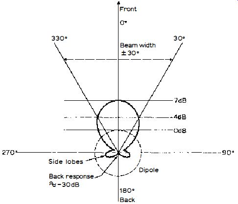
Fig. 7.7· Illustrating the primary aspects of a polar diagram (see text
for details).
... accurately because the curves are plotted on a linear scale. The front-to-back ratio is thus around 37dB. It will also be seen that the response to signals arriving at the sides of the aerial is well down - apart from the small side lobes which not uncommonly appear in the polar diagrams of high gain Yagi aerials of the kind used for FM and TV. The high directionality makes it possible to discriminate against strong, unwanted signals arriving from directions away from the wanted signal . For example, it may sometimes be desirable to orientate the aerial for the least response of an interfering station, even if this means losing some of the strength of the wanted station, if the tuner's front-end is being overloaded by the interfering station.
Directionality is also useful for discriminating against multipath interference (reflected signals) and thus for reducing multipath distortion (see Section 3 under Capture Ratio). A directional aerial on a rotator makes it possible to 'beam' on to distant stations , a technique used by DX buffs . Bandwidth This expresses the frequency range over which the aerial usefully operates. An FM aerial should have a bandwidth from about 88MHz to 100-MHz at least-- to a higher frequency if you are interested in receiving European stations. The polar diagram and the terminal impedance should not vary much over the bandwidth, which is the hallmark of good aerial design.
Headphones
Most headphones are of the moving-coil type, adopting the same principle as moving-coil loudspeakers but with a significantly reduced power input requirement. The type indicates the operating principle while also signifying other features. The two principles which predominate are moving-coil (sometimes termed dynamic) and electrostatic.
The moving-coil type can be plugged directly into a hi-fi amplifier, tape machine, etc. for monitoring, but the electrostatic type require the use of an additional unit which provides the polarizing potential. This is generally also plugged into the mains supply, although in some cases the polarizing potential is derived from signal rectification. Also, a fairly high drive voltage is needed for electrostatics, which is derived from a transformer in the unit.
Electrostatic headphones are not usually very suitable for connecting to a tape machine or preamplifier, and when used with a power amplifier connection cannot usually be made to the headphone jack socket . The signal for the add-on unit is commonly fed from the loudspeaker terminals of the amplifier.
Headphone Weight
This parameter can be important if protracted use of the headphone set is contemplated; you should also take account of the weight of the connecting cable! Weight including the cable averages about 350g, though there are some lighter (and heavier) ones.
Headphone Impedance
Headphones have quite a wide range of impedance. Some models are quoted at 4-8 ohm, others at 16, 200, 60 and 100 ohm or more. With most of them, however, direct connection to the headphone jack socket on the amplifier, etc. is possible, except for the relatively insensitive, low impedance designs , which sometimes work better connected to the loudspeaker terminals.
Some cassette tape recorders are critical of head phone impedance and if the impedance is not just right the recording level may reduce when the headphone set is plugged in while recording. This is indicated by a fall in VU meter indication.
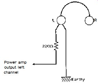
Fig. 7.8: Each unit of a headphone set is connected to the appropriate
channel of the amplifier via a 'hold off' resistor as shown . This limits
the current and hence the signal voltage across the unit.
------ Power amp output left channel
Headphone Sensitivity
This parameter is expressed as the input voltage required for a stated SPL. For example, a parameter of '96dB SPL/ 100 mV' indicates that each unit requires 100m V of signal voltage across it to yield 96dB of SPL. Maximum Input This states the maximum voltage that each headphone unit can withstand before failing. Some models can accommodate 5V r.m.s. or more with provision for 14dB transients above this . Used normally, it is unlikely that a head-phone set would suffer damage as the result of over-drive. This is because each unit is connected to the power amplifier via a resistor of 100 ohm or more (usually more like 220 ohm), as shown in Fig. 7.8.
You could, of course, damage a headphone set by connecting it across the loudspeaker terminals. A 50W amplifier, for example, could produce up to 20V r.m.s. of signal when driven hard. When connected to the headphone socket, however, the series resistor limits the current and hence the voltage developed across each unit . Frequency Response Hi-fi headphones are capable of extremely high quality of reproduction when correctly fitted. The low bass notes require intimate acoustical coupling to the ears , while the high treble notes require a diaphragm of low effective mass . Good quality headphones have a frequency response from, at least, 20Hz to 20kHz.
Distortion
Measurements of headphones are made with a dummy ear, including SPL output relative to input voltage (e.g., sensitivity) , frequency response and distortion. As with loudspeakers , the distortion tends to rise with increasing input and hence SPL; but good designs should not produce much more than 0.5 total harmonic distortion at 100dB SPL.
Cord-less Headphones
In recent times, headphones have been made which operate from a mini-infrared receiver . This eliminates the connecting cable from amplifier to headphone set. At the amplifier is connected a mains-powered transmitter which incorporates light-emitting diodes (LEDs) operating in the infrared spectrum.
The diodes are modulated with the audio signal at the amplifier and the signal is thus propagated within the room as 'invisible light' . The receiver, which uses 'photo cells' responsive to the infrared emission, effectively demodulates the signal and changes it back to audio signal again. The audio is then amplified and fed to the headphone set.
= = = =