Dial Belt Replacement--Managing on a Shoestring
Many radio receivers still use belts instead of cables to operate the dial movement mechanism. Sizes of these belts vary. There is no standard, and keeping many sizes in stock is a problem. However, the ordinary shoestring is a near approach to a "universal" belt.
To make the substitute belt, wrap the string twice around the pulleys, as shown at A. Pull the two ends tight and knot them as shown at B. With needle and very strong thread, sew the string at the two points as shown; after which snip the strings beyond the sewn places (sketch C). Put a dab of cement under each clipped end, applying a clamping pressure with long-nose pliers until the cement has set; then let dry. Thus prepared, the belt will glide smoothly over the pulleys, especially after a liberal coat of dial cord dressing. I've used one such shoestring--belt for over two years.
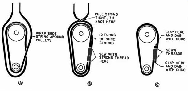
--- Step-by-step procedure for custom-fabricating dial belt substitutes
with ordinary shoestring.
Odd Buzz Cause
As the saying goes, there is always a first time. Recently we found ourselves face-to-face with a case of "intercarrier buzz" that wouldn't lend itself to the customary cures.
After a while, the condition was traced to an open screen bypass condenser in the sound I-F amplifier or ratio-detector driver tube. This was the first failure of its type m the writer's experience. The information is worth keeping in mind for future reference. It can save the technician considerable time in finding out the hard way that the condition is not caused by vertical circuit radiation or undesirable coupling from the sync circuits, before he investigates the simpler possibility.
Wiring Replacement Yokes
When a defective deflection yoke is replaced with another that is entirely acceptable, but that is of another brand, it often turns out that the picture is upside down or reversed from left to right or both, because of differences in the color coding of wires. With a picture on the air, it is not difficult to get the raster right side up, but there is often no way to identify the hook-up of the horizontal section unless one wants to spend time waiting for some writing or lettering to show up in the picture.
Delay can be avoided, I have found, by using the vertical retrace lines as an indicating device. The retrace lines always slant down to the left and, when a picture is on, have a break in their structure on the left side of the screen. See part A of the illustration. By reducing contrast and increasing brightness, these lines can be made visible on most sets.
When no picture is on the air or no antenna is handy, the vertical linearity and height controls can be used to determine whether the raster is right side up. Manipulation of the linearity control will compress or expand the top half of the screen, while the height control will show similar action on the bottom half.( See part B.) In some receivers, the reverse effect is shown by the vertical controls.
(As far as left-to-right deflection is concerned, you're still not cooked if you have no picture or if an effective blanking circuit kills off all re-trace lines. You can temporarily misadjust the horizontal drive control to produce bright vertical lines. If the yoke is properly wired, these lines will appear at the left of the raster. When using this method, be sure to note the original position of the control, to which it should be restored after misadjustment has served its purpose. Ed.)
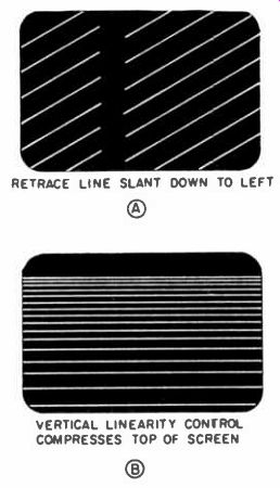
------- RETRACE LINE SLANT DOWN TO LEFT VERTICAL LINEARITY CONTROL COMPRESSES
TOP OF SCREEN
Antenna Helper
Did you ever stand on a ten foot ladder leaning against a guyed TV mast, on a peaked roof forty feet from the ground, removing a defective rotor and holding a stacked yagi in one hand-wondering whether to drop the yagi and then fall, or vice versa? If so, you may be interested in this time-and-life-saver. This gimmick will hold the antenna while you remove the rotor.
A piece of 1 1/2" tubing 18" long is bolted over a piece of 1 1/4" tubing about 3' long. Two pieces of 1 1/2" angle iron about 12" long are attached with antenna "U" clamps to the main body. At the opposite ends of the angle irons, drill 3/7" holes for a pair of 1 1/2" muffler clamps. See Fig. C.
Here is how it works. When the mast is telescoped down to a point where the rotor can be reached, the "little helper" is clamped to the mast, as shown in Fig. B. The antenna with stub mast is lifted out of the rotor and dropped into the big end of the helper, as illustrated. This procedure now frees both hands for removing the rotor and supports the antenna until the repaired rotor is returned. It has the added advantage of allowing the customer to use his antenna in one fixed direction while repairs are made.
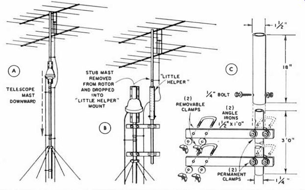
---------- Fig. (A)-The antenna helper is clamped to the mast after the
mast has been telescoped down to position. (B)-The short mast holding the antennas
is disconnected from the motor and then lowered into the helper's large end.
(C)-Component dimensions of the "little helper."
Buzzing Radio
An ac-dc set was brought in with the complaint of intermittent buzzing noises, which were finally traced to an unexpected source. On a similar complaint, you are advised to check the pilot bulb, if any, on the set. In this receiver, the bulb appeared to have a steady normal glow, but the guess is that it was arcing. In any case, replacing the light corrected the buzzing condition. I now make it a routine practice, on complaints of this nature, to make a quick test of the pilot bulb before anything else is attempted.
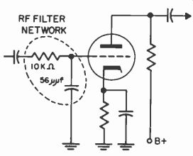
---------- RF filter inserted in the grid of the first audio amplifier
will bypass interference.
RF In Audio
In many high gain audio amplifiers, in P-A systems, tape recorders, radios, phono, etc., particularly those with a very high impedance first audio grid circuit, there is a possibility that very strong local R-F signals, regardless of frequency, may appear at the grid of the first audio stage. Under certain conditions, this R-F signal may drive the tube to the extent that it is caused to operate on a non-linear portion of its characteristic curve, and rectification (detection) could occur. If the R-F signal is amplitude modulated, the audio modulation could be detected, fed to succeeding audio stages, and be heard from the speaker. This could result in interference to the desired audio signal. If the volume control is located ahead of the first audio grid, it is possible that the control would have no effect on the volume of the interfering signal.
The interfering signal could cause all sorts of harmonic and other types of distortion in the audio amplifier, even though the R-F signal itself contained no audio or other amplitude modulation which could be heard, even after slope detection had taken place. The distortion would be due to the fact that the audio amplifier tube is no longer operating over the linear part of its characteristic curve.
The usual correction for this type of R-F interference is to install a simple R-F filter at the grid of the first audio amplifier tube. The diagram illustrates how a 56 uuf ceramic capacitor and a 10,000-ohm 1/2-watt resistor may be hooked up. Keep all leads as short as possible and get as close to the tube socket as possible.
A filter at the grid of the first audio stage is usually most effective because the R-F interference is eliminated regardless of its frequency or the means by which it entered the instrument.
Control Replacement
I recently had a popular 21" TV receiver in the shop with vertical chassis and printed circuit boards facing front. The vertical linearity control was burnt out. Normal replacement would have meant pulling the chassis and possibly the vertical horizontal sync board as well. These controls were the reversed type with the shafts through the control cover.
In an effort to avoid removing the chassis, I proceeded as follows: Remove the metal cover, the shaft and all the innards from the old control, leaving only the fiber base mounted on the board. Then, take the metal cover and sweat it back to back on a standard control, which in this instance was 5000 ohms at 1/2 watt.
Install the original control to the fiber base of the control still mounted to the printed board. Then, bend the tabs and, if necessary, solder on each side. Jump the lugs and a new control is installed without pulling the chassis from the cabinet or disturbing the printed circuit board. This procedure saves me immeasurable time.
----- Loose connections caused loss of raster.
Intermittent Fuse Clips
This could happen on any TV set equipped with a pigtail fuse which has been jumped by a fuse clip. This fuse is usually located in the horizontal damper stage. I have serviced many sets with intermittent rasters.
On quite a number of them I have found one or both of the rivets in the fuse clip to be either loose or corroded; causing intermittent operation. How many hours of work or waiting I could have saved if an article like this were written previously? The majority of the complaints were that the raster would operate at highly irregular periods of time, cutting in and out; thus making TV viewing a thing of chance rather than a certainty. Many times when the raster went out, it could be brought in again by flipping the on-off switch several times. The surge would cause the defective connections to arc together, momentarily effecting a cure. There are two things to watch for when the set is being serviced, assuming the tubes and fuses are all right. If the raster does not come in when the set is turned on, short out the original blown pigtail fuse using a jumper wire. If the clip is at fault the raster will come in. If the raster does come in when the set is turned on, grasp the insulated portion of the clip in your fingers and twist it. If the clip is at fault, the raster will go out with little effort. Soldering the fuse clip connections would eliminate this source of trouble. One hand on the cheater cord may save a flyback when jumping the fuse.
Supply Voltage Polarity
A customer brought in a dead transistorized auto radio that had been removed from his car. He returned a few days later and was told that the radio played perfectly on the bench for two days and all the usual routine checks had been made.
Suggesting that the speaker or antenna may be defective, the customer brought in the speaker. The speaker checked out good and with radio and speaker installed in the car, the antenna also proved to be good; however, the radio still didn't play. Again, one of our servicemen removed the set from the dashboard and connected it on the test bench.
To our amazement, the radio immediately played again. The next step was connecting it under the dash of the car where some measurements could be taken. The first voltage reading gave a clue to the dead auto radio. The minus lead of the meter was connected to the chassis and since the 12 volt battery supply voltage was being checked, the 50 volt range on the meter was switched on. The meter needle hit the peg in the opposite direction! The schematic indicated that the polarity of the supply voltage was negative ground. A further check was then made of the car battery.
The hot lead and post was plainly marked POS and the NEG post went to the frame. Here again, the voltmeter indicated opposite polarity.
Confronting the customer, I learned that he had recently serviced the car and battery, and shortly thereafter, his radio stopped playing. Evidently, one of the station attendants reverse-charged the battery. A dead battery can take a charge of reversed polarity and the car's electrical system will work properly, including the generator, since the field voltage will then be reversed and continue to maintain the battery's new polarity.
Fortunately, the transistors were not damaged and the customer was referred to a gas station to correct the wrong battery polarity.
Battery Eliminators For Transistor Car Radios
Hybrid and transistor car radios may be operated satisfactorily from the ordinary battery eliminator--by the addition of the filter network shown in the diagram. As these sets have a low drain, a 3 to 5 ampere choke will pass sufficient current.
The shorting switch by-passes the choke when regular sets are under test and when more current is needed. With this switching method, no extra terminals are needed to connect the transistor sets. The extra filter capacitor is always in the circuit and provides better filtering action even with the choke shorted out. The voltmeter connection should be attached to the output side of the choke, to allow for the voltage drop across the choke, and to indicate the actual voltage delivered to the unit under test. The two extra components may be mounted externally if there is insufficient room in the original power-supply cabinet.
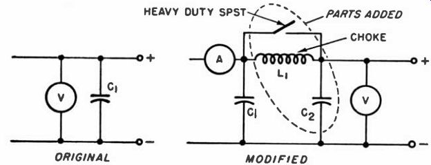
--------- Modified battery eliminator can be used to service transistor
and hybrid auto radios.
Improved Sensitivity
A fairly recent model TV receiver had a very annoying case of RF interference with its typical herringbone design superimposed on the picture. Since this interference persisted at all times it seemed likely to be coming from the set itself.
Quite by accident it was found that when a hand was placed on the shell of the 6AC7 video-output tube, the interference would be completely eliminated. Further investigation disclosed that pin 1 was grounded to the chassis by means of a lead about 11" long. By bending the lug of pin 1 and soldering it directly to the chassis, the RF radiation is eliminated.
It is interesting to note that in receivers cured of this or any other type of RF interference the sensitivity of the sets is also improved.
RF interference when picked up as a signal effects the AGC voltage and tends to reduce the sensitivity.
Alignment Jig
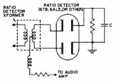
When aligning the ratio detector in the audio section of a television set using a 5T8, it is necessary to obtain zero output at the electrical center between pins 2 and 7. Normally it would be necessary to temporarily solder in a pair of matched resistors across these two points. The zero output indication would then be taken from the junction of these two resistors and test point V. The top of T301 (secondary) is the adjustment for this purpose. Tune for a dip between two peaks. Other adjustments call for a maximum from pin 2 to ground. Top of T154 (secondary) and bottom of T301 (primary) are used for these adjustments.
To avoid soldering and unsoldering to the printed wiring board, and to speed up alignment procedure, two matched 100,000 ohm resistors are tied together at one end and the other ends soldered to the external portion of pins 2 and 7 respectively of a q-pin miniature vector socket.
One alligator clip with a short lead may be soldered to pin 2 and another to the junction point of the two resistors. Insert socket between tube and chassis, tune in a station and hook up a VTVM.
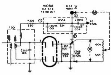
------- Typical ratio detector showing meter and resistor connections for
sound alignment.
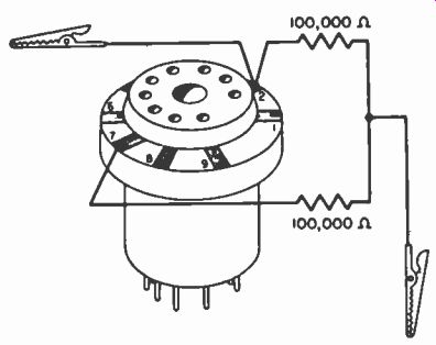
------ Vector Socket becomes handy alignment jig.
Watch Those Phony Symptoms
The design of the age system and the use of intercarrier sound in some receivers can often work too well, in the sense that they serve to mask some symptoms that would otherwise lead clearly to antenna faults, as this case history shows: The picture on the set would occasionally flicker, roll and pull to the right. The antenna appeared in order. The set worked perfectly in the shop, and was returned to the owner. When the symptoms recurred, since the owner did not want to be without his TV, arrangements were made to provide him with a loan-out set. Although the latter was in good working order, it did not have an agc system, being an older set. When this set was operated from the customer's antenna, there was sputtering evident in the sound and the picture flickered snow. Examination of the lead-in wire, which looked good externally, revealed several small breaks at different points in the separate strands once the plastic coating was stripped away. The agc network in the customer's own set had served to equalize the changes in signal level due to the break, and thus mask the condition.
Alignment Time "Shaver"
Like many useful tips, this was found by accident. I had some TV sets-in noisy locations and found that, by carrying my electric razor with me, putting it into operation beside the set, and adjusting the ratio detector secondary carefully for a definite and critical null in the noise, I could achieve very good noise rejection. But that isn't the end of the tip. There came a day when it didn't work. I eliminated the AM noise all right, but the FM sound was then garbled. Good sound and good AM rejection occurred at different settings of the secondary slug. Fortunately the primary adjustment is also accessible from the top of the chassis on this set if the correct hexagon alignment tool is used. I turned the primary a little clockwise, and then tried the secondary again. The two points (good sound and good noise rejection) had moved a little closer together. A touch more clockwise on the primary, and good sound and good rejection then coincided on the secondary. I later confirmed this procedure on the bench.
Now I can set up both the primary and secondary of the ratio detector transformer without using instruments--unless you call the razor a test instrument!
Damper Kills Sound
When some technicians confront a TV with no raster and no sound, they suspect, and rightly so, B+ trouble.
After checking the fuses, low voltage rectifiers, etc., and the trouble is not corrected, they frequently determine it's a shop job.
A set with these symptoms was brought into my shop recently and, once on the bench, the trouble was quickly traced to a defective damper tube. A glance at the schematic showed that the 6DT6, a gated-beam sound discriminator, received its B+ from the boost line (below). Sound was promptly killed when the boost voltage line became defective.
To avoid an embarrassing situation, the damper should therefore he checked when both sound and raster are missing.
When making voltage checks at the plate of this tube, a multiplier probe should be used on the VOM or a 1 meg resistor connected in series with the regular meter probe because of the high pulse from the boost line. It also follows: since the boost voltage is the sum of regular 8+ and d-c voltage developed from the flyback pulse, if a stage that contributes to the flyback's operation fails, the added d-c voltage in the boost circuit will be missing. Therefore, if the horizontal oscillator or output stages are defective, not only will the raster disappear, sound may also be reduced due to the lowered B+ to the sound section. -Ed.
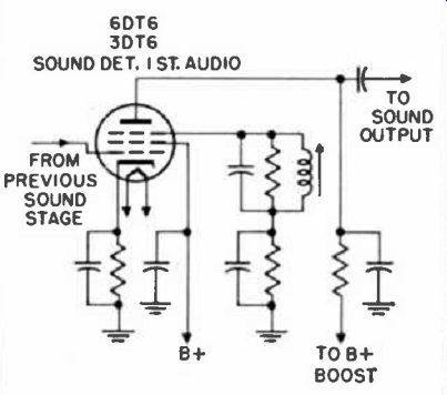
---- When a TV set's first audio stage is powered from B + boost, loss
of raster and sound occurs when damper tube ceases to conduct. Failure of preceding
horizontal stages results in lowered sound volume.
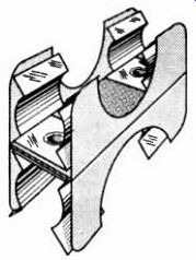
Weak Tuner Contacts
As turret-type tuners age, the contact springs, which are made out of brass, lose their springy quality. As this happens they become flatter, and the result is poor contact with the various r-f and oscillator slugs as the drum is revolved, with impaired or intermittent reception. This condition is illustrated to the right in the accompanying illustration.
The remedy described here for this flattening has proved its success for the writer. After the individual contact springs have been brought back to original shape as much as possible, a strip of spaghetti is used to retain that shape. The writer uses polystyrene spaghetti, about 1/9 in. in diameter, and pushes it through the openings in the contact springs. This spaghetti keeps the springs open, preventing flatness and thereby assuring continued good contact between the revolving drum and the stationary springs. A strip of foam rubber with an oval cross section would be just as practical for this function. The position of the strip is shown to the left in the accompanying illustration, which is an internal view of the tuner with the turret drum removed for the sake of clarity.
If any of the contact springs are found to be broken when this job is undertaken, the entire contact plate should be replaced. The spaghetti can be run through the new springs, as a preventive measure, before the plate is mounted in the tuner. Another good practice is to remove permanently the slugs for all channels not used in the area. This gives the springs a chance to "stretch" between channels as the drum is revolved, thus prolonging life of the contacts.
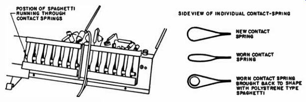
---- Spaghetti run through turret-tuner springs restores their shape and
maintains good contact.
Radio 1-F Xformer Checker
A common complaint in today's 5- and 6-tube AM radios is low volume, and quite often one or both of the I-F transformers are at fault. Because defective I-F transformers may often show the proper resistance and appear to tune normally even when they are bad, it is difficult to reach a decision concerning them without going to the trouble of unsoldering all leads, removing them, and trying out a replacement transformer. A simpler and less time-consuming test substitution can be made with the unit described here.
Procure a good I-F transformer tuned to 455 khz and solder four 3-in. leads to each terminal; then attach a narrow, insulated alligator clip to each lead. The leads should be coded by using wires of different colors.
Now when an I-F transformer is suspected of being defective, simply unsolder one lead from its primary and one lead from its secondary (it generally won't matter which) to remove the old transformer from the circuit, and clip the substitute unit in its place. Check alignment. If the original unit was defective, the clip-on substitute will restore normal gain and performance. Because of the long leads, an occasional set may squeal. If it does, try reversing one or both of the windings. Squeal or no squeal, positive results can be obtained.
Aligning Auto I-F's
In auto radio production, wax is normally dropped into the I-F core to prevent it from moving after alignment. The wax must be melted before attempting to turn the core, or damage to the transformer will occur.
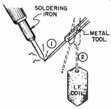
------- Heating an alignment tool unfreezes wax dropped into I-F cores
during production.
To prevent damage, simply heat the tip of a small metal alignment tool and insert it into the wax as shown above. Repeat this two or three times until the wax is melted and the core turns easily. Avoid forcing the core.
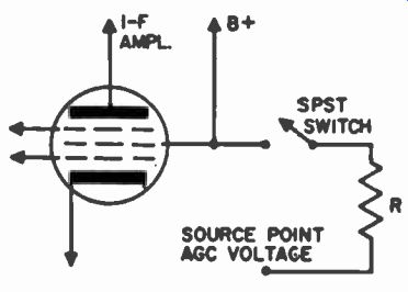
--- Circuit for simple "fringe-local" switch.
Fringe Improvement
In an attempt to boost sensitivity and gain in fringe areas, some technicians either ground the agc voltage entirely, or attempt to reduce the no-signal agc voltage by sometimes involved and devious circuit modifications. When such receivers are returned to normal signal areas or when increases in transmitter power eliminate the need for the change, extensive alteration is again required to restore the receivers to proper operation. Also, a permanent internal change creates difficulties where the same set is required to work on weak and strong signals on different channels.
A much better idea is to install a simple "local-fringe" switch, if the circuit doesn't have one. This gives the owner some external means for adapting the set to different conditions without having to rewire it. A study of many commercial variations in actual sets and some actual experimenting shows the circuit presented here to be simple, easy to install and effective.
B-plus is taken off at some such point as the screen grid of one of the I-F tubes and applied to the output of the agc circuit through a resistor of high ohmic value. The point to which this bucking voltage is applied is the one at which external bias would be connected during alignment. A typical value for resistor R would be 15 megohms, though experiment may indicate another value in individual cases. As illustrated, closing the switch will generally reduce the age voltage from about minus 2 volts to about minus 1 volt, as measured with a vtvm.
Reverse Coupling
I have found it practical in fringe area installations to reverse the hookup of a line splitter and use four different antennas with but a single lead-in to a TV set. On the line splitter 1 feed each separate antenna into the output and the single lead-in to the input. Instead of splitting the line this has the effect of mixing four different signals into the single lead-in.
In one case I have been using a commercial line splitter as a mixer for Channels 4, 8, 38 and an FM station. Results seem to be as good as using four separate lead-ins from each of the antennas stacked on the antenna mast.
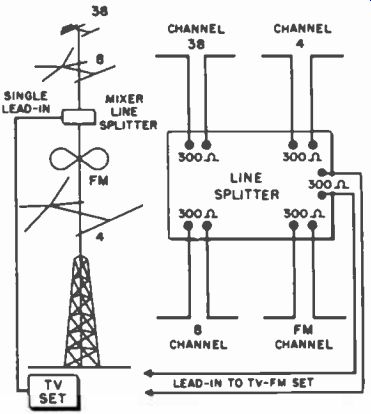
----- Coupler used to connect 4 antennas to 1 set.
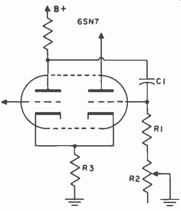
Horiz. Oscillator Blocking
When used as a horizontal multi-vibrator-type oscillator, the 6SN7 will sometimes show a tendency to block. The symptom is either a double image, which may be intermittent, or a sudden cutoff of a part of the horizontal scan for a number of lines.
The difficulty crops up if the value of the coupling condenser, C-1, going from one plate to the opposite grid (the one to which the hold control, R-2, is connected) is too high in value. If residual gas in the tube is high, a value for C-1 in excess of 2000 mmfd may cause blocking.
Remedial measures include lowering the value of C-1 and trying other tubes. Note that, as far as tube replacement is concerned, a seasoned tube is less likely to have excessive gas than a fresh one.
---------
In substituting a part with less capacitance for C-1, note that the value of resistance in the circuit (R-1, R-2) may have to be increased correspondingly to maintain the proper time constant. The percent by which circuit resistance is increased should be about the same as the percent by which capacitance is decreased. For example, if a 2500mmfd condenser is replaced with a 2000-mmfd unit, reduction is by about 20 percent; so resistance would be increased by about the same amount.
Loopstick Adjustment
Widely used as original AM receiver antennas as well as for replacement, the adjustable loop stick type aerials are often annoying and tedious to adjust. As the coils come from the manufacturer, they are provided with a tiny screwdriver slot at the end of the core's screw, often making them difficult to tune. Much time can be wasted in attempting this procedure with the small screwdriver.
By soldering an ordinary lug on the screw as shown in the accompanying illustration, you can easily speed up the process of tuning and adjusting. If space around the loop-stick coil is at a premium, the lug may be conveniently bent at right angles. Also, if it is desirable to do so, the lug can be snipped off shorter than is shown. It will still provide a convenient way of making the desired adjustments.
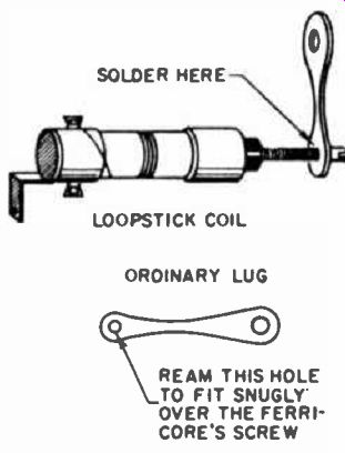
-------- Lug on loopstick coil facilitates adjustment.
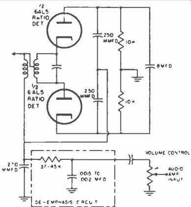
De-Emphasis Trouble
Shrill sound with ample volume and an apparent loss of low notes in TV or FM sets indicates possible trouble in the FM detector's de-emphasis circuit. This R-C network, located between the detector output and the volume control (or the grid of the 1st audio amplifier), consists of a series resistor-condenser combination (see sketch). It restores normal tone balance-a measure made necessary by pre-emphasis of high frequencies at the transmitter. New sets often develop the trouble cited, due to excessive heating of the resistor-condenser components during assembly. Sometimes weakness of the internal connections (usually of the condenser) escapes inspection, showing up after a few days service in the set owner's home.
The condenser may be tested for a partial or complete open circuit by shunting it with another unit. If this check restores the proper tone balance, replace the defective condenser--do not permanently shunt it with another one. If the resistor has changed value-usually the result of aging-the trouble can readily be located with an ohmmeter.
----
Tuner Substitution
The following gadget enables me to eliminate front-end trouble very rapidly; simply by substituting a tuner known to be good. Two TV front ends are mounted on a board together with an AC power supply, coaxial leads with alligator clips attached and an AGC control to avoid overload. Two tuners are used to accommodate sets with different I-F frequencies, one for about 20 mc and the other for approximately 40 mc. If a set has low gain or other trouble and the front-end is suspected the tuner of the TV set is switched to an unused channel to avoid oscillation, beat frequencies, etc. Connect the proper lead to the first I-F tube, set the AGC control on the gadget and a difference in picture quality will usually give a clue as to whether or not one has to dig into the tuner of the set or if the poor gain is caused in the I-F amplifier, demodulator, etc. The component values of the gadget are not critical and were found experimentally. The 1000-ohm control is wirewound, the 5000 and 1500-ohm resistors are 5-watt. The coaxial cable should be of the low-loss type and no longer than necessary.
It may be necessary to disconnect the lead from the set's tuner, going to the 1st I-F, even though the tuner has been set on an unused channel
-Ed.
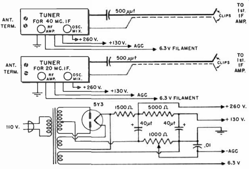
-------- Two tuners and power supply mounted on a board quickly substitutes
TV set's front end.
Auto Radio Noise
Before attempting to troubleshoot an auto radio afflicted with undue static, open up the drain hole in the bottom of the aerial (with which some antennae are equipped) and let the water out. The drain holes in some of these aerials become clogged, and allow water to accumulate in the tube, with noisy reception resulting in consequence.
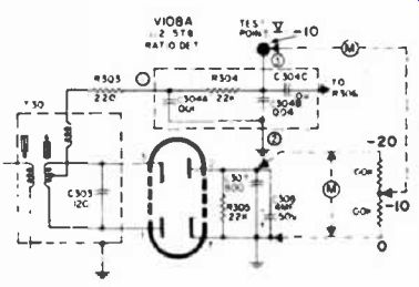
Buzz Correction
Leakage in an electrolytic condenser is a common component failure. When leakage occurs in an electrolytic condenser used in the ratio detector circuit of a TV receiver (condenser C in the figure), buzz results.
----------
Before starting a time-consuming search for other sources of buzz, an ultra-fast check of this capacitor can be performed without even removing the back of the receiver. Rotate the fine tuning control back and forth rapidly. This will vary the average voltage across C. If the condenser is leaking, the rise and fall of volume will be erratic, and may be accompanied by a clicking sound, whereas if the condenser is good, the rise and fall of volume will be smooth.
Hot Shot
Elusive and troublesome intermittents in sync and video sections, plus buzz and many other difficulties have been caused by poor ground connections on some of the GE dip-soldered chassis. Riveted ground connectors, in time, develop high resistance joints due to electrolytic or corrosive action. Spurious signals sometimes develop across these high resistance ground joints and inject themselves into TV circuits causing all sorts of weird effects. In some cases even the filament string will decide to dim a bit and really cause a few gray hairs. Soldering these eyelet ground connections is the simple solution, but it requires more heat than some of the soldering equipment is capable of producing.
One very effective way to eliminate these poor grounds is to build up a bank of 300 or 400-volt electrolytic capacitors to about 500 of or more, then charge them up on a 300-volt B+ power supply, and then discharge them between the eyelet and chassis. The heavy current surge will effectively spot weld the eyelet to the chassis. All the ground eyelets can be treated in this manner in a matter of minutes. To prevent accidental discharge to other parts, contact the eyelet first, with one lead, and then the chassis with the other lead. It is advisable to use a separate fused power supply to charge up the capacitors to avoid drawing excessive current and damaging the set's rectifiers. An alternative is to charge the capacitors through a resistor and thus limit the current surge. Safety first, discharge the capacitors before putting them away, and avoid contact with the hot wires.
Tracing H-V Arcing
Many times arcing or corona cannot be easily located by sight. A convenient way to run down these elusive cases is to work with a length of spaghetti tubing, using it as a stethoscope. Cut a piece of tubing about 18 in. long. Use the largest diameter that will fit inside the ear.
With one end of the tubing held to the ear, probe around the high-voltage supply until the one point is reached where the sound of arcing can be heard the loudest. Need it be suggested that the hand holding the tubing be kept away from dangerous points of contact?
Quick AGC Check
A shortcut that is frequently helpful in troubleshooting agc-related stages, such as the I-F strip or the tuner, involves a meter check on either side of the resistor in the agc line. Readings taken on either side of the resistor (usually 500k to 1 meg) shown in the sketch should be very close to each other. If the reading is noticeably higher (less negative) on the side of the resistor nearest the condenser than it is on the other side, a defective tube or a defect in the tube's circuit is permitting too much current to be drawn, and the age line is being loaded.
To localize the bad tube or stage, leave the vtvm connected to the point along the age line where the high reading is obtained and substitute or remove tubes in the video I-F and tuner sections. If substitution or removal of a tube restores the reading, so that it is the same on either side of the resistor, the fault is localized.
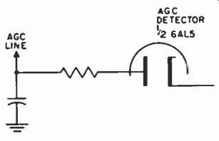
------ Check on each side of resistor shows fault.
TV Oscillator Alignment
When aligning the lower channels of some wafer type tuners using series-type inductors it is sometimes necessary to compress or expand the oscillator coils to obtain the correct frequency. It is quite easy to mutilate the coils after a few attempts of first expanding and then compressing. I have found the following method to be quick accurate and minimizes manipulation. Loosely couple a marker generator to the antenna or oscillator tube, center the set's fine tuning control and leave it there. Connect a wire from the grid of the mixer tube in the tuner, to the top of the set's volume control, and tune for zero beat. Start with the highest channel, and work down. It is important that the generator be properly set to the oscillator frequency of the channel being aligned. It is also desirable to disable the sound I-F section. This can be done by pulling one of the sound I-F tubes, or shorting the sound I-F signal to ground if the set is of the series string type.
Re-Mounting Pulled Chassis
Have you ever fumbled around trying to line up the mounting holes of a TV chassis with the holes drilled through the cabinet shelf? Or have you ever had the customer tell you that the picture tube was just a bit farther to one side than it should be after you had bolted down the set? You can reduce such occurrences if you (before pulling the set) simply outline the position of the chassis on the wooden shelf by running the point of a pencil along the bottom edges of the two sides and the rear. When you re-install the set, simply fit the chassis to these guide lines. Then see how the bolts go easily into place. The picture tube should be where it was before, unless you moved it on the chassis.
Perhaps the time when this hint will be most valuable is when you try to locate the position of a side-mounted chassis on the board which slides vertically into the grooves of the cabinet. Since the chassis must be bolted to the board before the board is slid into place, there is no way of compensating for errors in mounting. Marking the outline of the chassis on the board will enable you to fit the chassis in the same position it occupied before removal.
---------- FM discriminator can be aligned without the use of jigs or external
resistors.
No Alignment Jig
The following method permits alignment of an unbalanced ratio detector without a jig or other external resistors. When the jig or other pair of equal resistors are placed across the load resistor, the junction point or center of the two resistors is at a potential of half the voltage across the load resistor, as shown by the dotted lines in the diagram. The meter is then connected between this point and the center tap of the ratio detector transformer circuit, test point V. The transformer secondary is then adjusted for zero volts.
Since the potential difference between test point V and the center point of the two resistors is zero, and since this center point is half the peak voltage (in this example-10 volts with respect to ground) test point V would also be half the total voltage, with respect to ground.
Therefore, we can dispense with the jig, and make the alignment with the VTVM only. Attach the positive probe to the chassis and the negative probe to pin 2 of the tube. Adjust the primary and preceding stages for maximum voltage. Transfer the negative probe to test point V and tune the secondary for one half of the maximum voltage. Recheck the voltage on pin 2 for maximum and readjust if necessary.
Sometimes while adjusting the secondary of the detector transformer the primary becomes de-tuned. It is good practice to rock the adjustments to make sure that tuning is optimum.
To verify the meter reading for exactly half the maximum load voltage at test point V with respect to ground, alternate the position of the positive lead from ground to pin 2 of the 5T8, while the negative lead remains on test point V, the two readings obtained should be exactly equal. -Ed.
Inaccessible Adjustments
Sometimes the manufacturer of the TV set, showing little concern for the service technician, will mount I-F transformers and other tunable coils directly under the bell of the picture tube, where alignment or other adjustment is practically impossible without taking the set apart. With some of these adjustments, a little ingenuity will eliminate the need for dismantling.
For example, in the case of bifilar I-F transformers having cores with threaded brass spindles, the slotted spindle is generally brought through the top of the chassis and is often all but inaccessible, being under the pix tube bell or the yoke assembly.
If the core is screwed all the way out of the coil form and a slot is cut with a fine hack saw in the molded end, it is generally easy to align the set from the underside. Bifilar I-F transformers are mentioned because one end of these units is often open. The idea is equally applicable to tunable I-F chokes and other units.
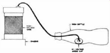
Safe "Cache" for HV Lead
In many of the older-model television sets, the picture tube is separate from the chassis. To eliminate danger of high-voltage shocks, when working on this type of chassis (without the picture tube), just slip the high-voltage anode cap into an empty soda pop bottle, and put the latter to a side (see sketch).
-------
Deodorizing Receivers
It may sound strange, but some receivers have to be deodorized.
This writer had to replace a burned-out power transformer. The job turned out quite well, except that the customer objected to the burnt odor that persisted despite a thorough clean-up attempt. Finally I hit on a very simple method that really worked. Reasoning that even a perfume does not smell when properly corked, I corked the burned areas by spraying two coats of plastic spray (Krylon) over the discolored areas. The smell disappeared. Do you have a customer allergic to odors of burned transformers, resistors, and selenium rectifiers? Try this method, it works!
Shaft Repair
I received a clock radio which had a broken "alarm-set" shaft. A gear assembly is attached to this shaft and to replace the entire unit would considerably raise the customer's bill.
Using an empty ball point pen cartridge, I repaired and extended the shaft by soldering this piece of tubing directly over the broken end, as shown above. I found the shaft to be slightly larger in diameter than the tubing, but made a small slit in one end of the tubing with a knife and small hammer. The tubing was placed over the broken end tightly by a few light taps with hammer, and then soldered to the shaft at the seam in the tubing.
The knob end of the extended shaft was pinched and heated with an iron while the plastic knob was pushed on.
The job required only a few minutes, circumvented ordering the entire assembly, and eliminated the necessity of having to present the customer with a relatively high repair estimate.
--------- Soldering an empty ball point pen cartridge to a broken clock
radio shaft saves time and reduces cost of repair.
Shunt Control The contrast control in the cathode circuit of the 12BY7 video amplifier had a clean break just at the point of optimum setting. No control in the tube caddy and the customer ready to pay a bonus if he won't have to miss the ball game. The break in the 1,000 ohm control was at the 300 ohm point from the cathode end. By reversing the connections I was now able to get a range of adjustment from 0 to 700 ohms which included the optimum point. Actually this was as far as I had to go, but the thought of establishing control over the remaining 300 ohms without getting a new control was a challenging one.
For what it's worth, here's how I worked it out. By connecting a 680 ohm resistor (didn't have a 700 ohm unit) across the control, the remaining range from 1,000 to 700 ohms was easily covered. If the crazy way the control works disturbs the customer, at least it works. I got the bonus too.
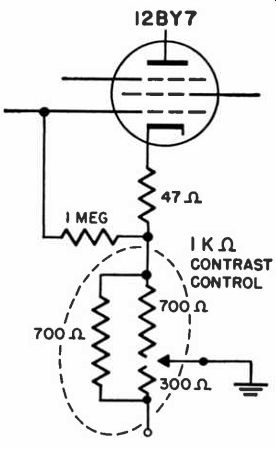
--------- Shunt restores control range in an emergency.
Weak, Noisy Radios
In our shop we have had an influx of radio sets with the following trouble: Reception is either weak or below normal with continuous static.
Turning the volume control down eliminates the static, indicating that the trouble is not in the audio.
The fault is in the type of I-F transformer used in these sets. They are slug-tuned, with fixed silver mica capacitors built-in, one across each winding. Minute particles of the silvered mica cause high resistance shorts between these two capacitors, with the leakage being so small that it often does not show up on the ohmmeter. However, there is enough of it to cause the symptoms described.
Where this trouble is suspected, it can be confirmed by disconnecting the leads to the secondary of the transformer and turning the set on.
A meter is then used to check for positive voltage on the secondary. If there is none, the leads are reconnected and the remaining I-F transformer is checked similarly.
Once the condition is established, a simple and permanent repair can be made as follows: Use the high voltage (approximately 700 volts) available from the secondary of a conventional power transformer.
Place a 5000-ohm 10-watt resistor in series with one lead. With the secondary of the faulty I-F transformer still disconnected, apply the high voltage between the two windings. This step will vaporize the particles of silvered mica and thus eliminate the short. After this operation, the I-F transformer should be retuned. This method has always worked for us.
Dial Cord Slippage
Repairing dial cable mechanisms on small radios is a frequent task. Often, because the sets are inexpensively made, annoying comebacks result as the repairs may not last too long.
In these receivers, the dial cable usually has only one spring at one of its ends. It is a simple matter to add another. Two springs will pull the cord much tighter, eliminating "sloppy" tuning and annoying backlash. Since they take up a greater amount of slack than one spring will, tuning action will remain "tight" for much longer. The very sharp tuning thus permitted is especially valuable if the set happens to have a shortwave band. In the long run, making the addition of the extra spring a standard practice results in a longer-lasting, customer-satisfying repair.
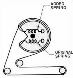
-------- Extra dial-cord spring improves radio tuning.
AGC Prescription
In most cases an aspirin will help. In many cases, I have found that a horizontal amplifier tube will check satisfactorily in a tube checker, but it will not function properly in the set. On those receivers deriving the AGC pulse from the horizontal output, with poor AGC action, the first thing to do is change the GBQ6, or 6BG6, regardless of how the tube checks out. Do not rely on this as a cure all. The more usual sources of this difficulty should not be overlooked. They are in part, gassy, leaky or shorted tubes, defects in the horizontal circuit, and defects in the load circuit of the flyback transformer. Defective damper tube, linearity coil and condensers, width coil, yoke, etc. and the flyback itself will affect the amplitude of the AGC pulse.
Improving TV Sound
Most standard TV and radio receivers use a single-ended audio output stage. Ordinarily, the cathode resistor is bypassed with an electrolytic condenser, which raises audio output somewhat, since it prevents some degeneration of the output by cathode signal. In such cases, removal of the condenser improves sound quality. This results from negative feedback (degeneration) at the cathode. The drop in sound output is usually not enough to prevent the user from obtaining as much volume as he desires.
Once the condenser is removed, the cathode becomes a good take-off point if it is desired to feed sound from the receiver to a separate amplifier or audio system, a tape recorder, or some other equipment, since it provides several advantages.
Among these advantages, aside from good audio quality, are the facts that audio amplitude is appreciable, that this take-off point is at the desired low impedance (the cathode resistor is seldom over 1000 ohms), that the take-off is of the cathode follower type, that one end of the circuit is already grounded, and that coupling condensers of a low voltage rating may be used.
A word of caution: some TV receivers use a stacked B-plus supply.
In these, the technique described is not possible, if the audio output tube is part of a voltage divider. In the latter case, there is about 150 volts on the cathode of the output tube, which is used as the low B-plus supply for other stages in the receiver, such as the I-F tubes. Removal of an electrolytic condenser will disturb voltage regulation to the other tubes.
Antenna Connector Gimmick
Clothespin type antenna clips are very convenient to use around the shop to allow quick connection to and disconnection from the antenna posts of TV receivers on the bench. However, any other technician will bear me out on this: so many times, in turning the chassis over for service or in mounting it on its side, the antenna lead gets caught on something, or else turns out to be too short, and the terminal strip is broken away from its mounting before one realizes it. After having this happen to several sets in the shop, I finally ended up with the idea of cutting the 300-ohm lead a foot or so behind the clothespin connector and inserting a pair of Mosley connectors (see illustration). Now, if there is any undue strain, it is the line itself that pulls apart, and no damage is done.
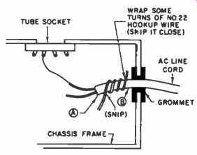
Line-Cord Anchor
Many receivers come into the shop without the protective knot on the line cord, inside the set. To unsolder the cord connections and knot the wire, then resolder the connections, takes a lot of time and work.
Wrapping the cord with many turns of tape, while the cord is still in place, is also tedious if a sufficient number of turns to do the job properly are wound on.
----------
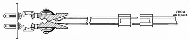
---------- Pull-apart antenna connector for bench use prevents damage to
receivers during servicing.
A quick, easy method is the technique illustrated in the accompanying figure. First, wrap a few turns of insulated hook-up wire around the ac cord. Snip the ends close, as shown. Then start winding some tape around the line cord at point A. Wind in the direction from point A to point B. This anchors the hook-up wire which, in turn, protects the line cord connections, and keeps them from pulling loose just as effectively as though a knot were tied on the end of the line cord. The whole job can be done in just a few minutes.
Instead of using ordinary friction tape for this job, I use the newer type of plastic insulating tape that may be stretched. It is easier to handle, is thin, is strong, and does not dry out, slide or unwind after exposure to heat, as does friction tape.
Flyback Repair
In a TV repair job the other day we found there was no RF voltage on the plate of the horizontal amplifier tube, and consequently no RF voltage at the input to the HV rectifier. When the 6BG6G horizontal amplifier tube was replaced with a new one, the RF voltage (as indicated by the spark drawn) returned to normal at the plate of the amplifier. A test of the original tube, however, indicated that it was good.
------
It was inserted into another TV set as a further check. Set operation was normal.
Several other new tubes were now tried in turn in the set being serviced.
Only a few returned the set to normal operation. Circuit checks seemed advisable. Voltage readings and scope waveform checks revealed no trouble in the horizontal oscillator stage.
Trouble in the flyback transformer seemed likely. Subsequent replacement of the flyback transformer verified that this was actually the case.
When the original 6BG6G tube was used with the new transformer, the set operated normally.
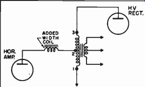
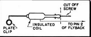
Before the transformer was replaced, a remedial measure was tried that worked out fine. The information just presented was intended to serve as an introduction to this little trick.
---------
I took an ordinary width coil and inserted it between the primary of the flyback transformer and the plate of the horizontal amplifier, as shown in the sketch. When the receiver was tried after this change, it immediately worked as it should.
I believe that a few turns of the primary winding in the flyback had short-circuited. The loss of resistance was so low that the average ohmmeter could not register it. The loss of inductance, was, of course, the important one. It is this inductance loss that the insertion of the width coil compensates for.
On another set in which this method was tried, and results measured, an originally insufficient CRT 2nd anode voltage was raised 1500 V by the series addition of the width coil to the horizontal amplifier plate circuit.
The method has been used in other cases where small but critical losses in flyback transformer primary inductance impaired circuit operation severely. The technique restored circuit operation to normal in approximately 75% of the cases.
The brass screw should be cut off from the width coil. The coil must also be very well insulated. We were fortunate enough to have some liquid plastic on hand at the shop which we used to dip the coil in. The bottom of the coil winding was connected to the plate lead, and the top layer or the beginning of the coil was attached to the flyback connection (terminal 2 in sketch).
Hidden Sputter
Intermittent fuse blowing fur no apparent reason and a slight sputtering sound clearly heard at times from the interior of the receiver were the symptoms on this portable television chassis. This trouble could also happen on other sets. All tubes checked ok, even when the damper, horizontal oscillator, high voltage rectifier and horizontal output tubes were replaced, the fuse would still blow out. Sometimes the receiver would operate for a day or two without trouble. With the rear cover plate off and a cheater cord plugged into the receiver, I allowed the set to operate while I went on about some other repair jobs. When the sputtering next occurred, I noticed a faint glow in the vicinity of the yoke. Fortunately I happened to be looking at the set just as it started to sputter.
I removed the CRT socket and ion trap, unsoldered the four yoke leads from the terminal strip on the chassis, and slid the yoke off the neck of the tube. Close examination of the yoke showed a small burned spot at the edge of the winding closest to the bell of the CRT. Matching this spot with the bell, I found the cause of the trouble. A foil-covered, thin-cardboard strip clamped around half of the yoke opening in the chassis had bent inward (possibly from electrostatic attraction) and was just touching the edge of the yoke winding. I bent and dressed the cardboard back out of the way, and cleaned the burned spot. Two coats of coil dope and two strips of high voltage tape cured the trouble.
Ringing in the Picture
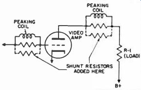
Whenever peaking coils are used as a means of increasing an amplifier's high-frequency response, the possibility of ringing or "echo effect" exists. This is the case with video amplifiers in TV receivers.
The symptom is often mistaken for tuner or I-F misalignment, with the result that there are fruitless and time-wasting attempts to align and re-align the set. If ringing occurs in the video amplifier, a simple solution is to shunt resistors across the peaking coils or, if resistors are already there, to reduce their value.
------
A good starting value is about 50k. This value may be lowered until the ringing is acceptably reduced. This method should be used when a test pattern is being received, so that the effect on high-frequency response can be noted. If high-frequency response must be reduced a great deal to eliminate the ringing, re-dress video amplifier leads so that they are as short as possible, and lower the value of the plate load resistor, R-1.
(Care should be taken in changing the value of the plate load resistor; reduction in the value of this resistor will lower the stage gain. The method may therefore be inadvisable where weak signals are being received. -Ed.)
High Voltage Checks
Rather than resort to the conventional but unreliable screwdriver method of probing for r-f arcs at the caps of the horizontal output and h-v rectifier tubes, the author uses a simple visual aid. Adapters were made to fit into the sockets of type 1B3 and 1X2 high-voltage rectifier tubes. Soldered into each of these adapters was a No. 47 (brown bead) pilot lamp, across the filament pins.
When the flyback system is normally putting out r-f (15,750 cps)
of sufficient amplitude, the pilot lamp, when inserted in the h-v rectifier socket by way of the adapter, will glow with the same amount of brilliance as when powered by a 1.5-volt cell. With the adapter in place, a direct visual indication is provided for observing the effects of flyback output when various circuit adjustments are attempted or when component values are experimentally changed. These effects are readily noted as changes in the degree of illumination in the pilot lamp.
Of course, this method is not as accurate as the use of a vtvm in conjunction with a high-voltage probe. However, this application has certain advantages to recommend it, including low cost of equipment used, ease of assembly and application, elimination of danger from shock, and the small size of the equipment such that it can be conveniently taken along and readily applied for checks in the home. Continued use of this method makes the technician adept at properly evaluating output and overall operation of the flyback system under various conditions. One learns quickly to evaluate degrees and changes of brightness in terms of operation and circuit defects. Frequent application makes the user adept. The method is certainly superior to that of probing for high-voltage arcs.
Antenna Attachment Jig
When the back is removed from many TV sets having a vertical chassis, it is necessary to detach the short antenna lead connector going to the tuner. This makes it difficult to attach the antenna for testing the set. I have solved the problem by making a jig, as illustrated, which I keep in my tube caddy.
Two alligator clips are soldered to the inside lugs of a regular screw-type antenna terminal strip. When the short lead from the tuner is detached and the set's back removed, the antenna can be easily connected to the strip and the connector tips from the tuner lead can be grasped by the alligator clips. The tuner lead is held taut, the leads kept well separated, minimizing the possibility of shorting the antenna leads.

---- An antenna is easily attached to a vertical TV by a jig made with
two alligator clips and a spare terminal strip.
Loose Back Covers
Push an appropriately sized paper clip into all corners and then insert the tri-mount clips. The paper clips enable the tri-mounts to make a positive mechanical hold in the enlarged plastic holes and keep the fiber back firmly in place.