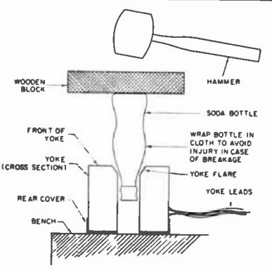
Neck Shadow Remedy
Occasionally a slight case of neck shadow is due to an inadequate flare angle in the yoke windings. To replace the yoke is the easiest procedure, but it is also the most expensive. Before resorting to replacement, try this simple expedient; it works fine in most cases:
Place the yoke on the bench with the rear portion, out of which the neck of the picture tube normally protrudes, face down. Also obtain a small soda bottle ("coke" type or similar), a soft rag, a small wooden block and a hammer. Arrange these items as shown in the drawing. The bottle-or that part of it which will be outside the yoke-is wrapped in the cloth to prevent personal injury in case of glass breakage. Tap the wooden block smartly with the hammer several times, to increase the angle of the yoke flare. Replace the yoke, making sure that it's as close to the picture tube bell as possible. You'll be surprised to find how often this gets rid of neck shadows.Incidentally, I have never had a "coke" bottle break in the years I've used this method.
------------
Ion-Trap Technique
When a picture tube has to be replaced, or even sometimes when a new set is being installed and set up, finding the proper position for the ion-trap magnet is a haphazard and often time-wasting procedure. The adjustment can be simplified greatly if the ion-trap assembly is started about one-half inch from the base of the tube, with the magnet itself in line with the socket keyway.
While this positioning may not result in perfect adjustment, it will be close enough so that the optimum point can be found quickly from this starting point.
CRT Filament Checker
Many times before putting together the simple testing device described here, I found it difficult to determine whether the picture tube filament was truly open, or whether it was simply the socket that was defective. Simply connect two leads to a No. 44 panel lamp mounted in a suitable socket. Insulated leads are used, but the ends away from the socket are stripped bare so that they can be used as prods.
If the CRT filament fails to light, I remove the socket from its base and insert the prods of the test lamp quickly into the filament connections. If the lamp lights, the CRT itself is the source of the trouble. This compact tool may be carried easily on calls. The system really pays off in time saved that would be spent in pulling out and setting up a meter to make the same test.
Saving a CRT
Some time ago a customer's set developed a heater-cathode short on the picture tube. Such a CRT can be continued in use if a way is found to prevent the cathode from being grounded by the short, through the grounded side of the filament supply.
This is done by using an isolation transformer between the CRT filament and the filament supply. In this case, the set was restored to normal operation with the old picture tube still in use by means of a universal pix tube booster or brightener that had a separate primary and secondary.
Recently, the set lost its raster completely. High voltage was normal. However, while measuring the picture tube's bias, I accidentally had my test prod short the cathode to the heater. Strangely enough, this caused the picture to return.
Some thought on the subject led me to the following conclusion: now the cathode was open, but cathode current could flow through the preexisting cathode-heater short. With the external short in place, cathode current could flow to its normal return, as indicated in the accompanying diagram. Since either open cathodes or cathode-heater shorts separately are rather common pix tube troubles, it is logical to assume that they sometimes occur simultaneously.
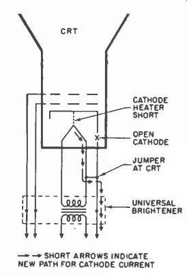
--------- CRT with cathode-heater short and open cathode is restored
with xformer and jumper.
In cases where the symptoms indicate an open cathode and the customer is unwilling to pay for a new tube, it is suggested that an isolation transformer be installed and that the cathode be shorted to the heater with a test prod or screw driver. If this experiment restores the picture, the full condition and the cure are both obvious. A permanent jumper from heater to cathode, as shown, will put the tube back in operation.
Neck Shadow Remedy
Many cases of picture tube neck shadow can't be completely removed by the ordinary methods, such as deflection yoke positioning, adjustment of centering magnets, focus coil positioning, and correct ion-trap magnet settings. These un-removable neck shadows are most often caused by slight irregularity in the construction of the picture tube itself, with the electron gun structure being out of alignment with the tube neck. Where round picture tubes are in use, there should be little difficulty in eliminating a shadow due to such a defect.
Assume that the shadow is evident in a portion of the screen as shown to the left in the accompanying illustration. Rotate the tube about a quarter of a turn one way or the other, so as to place the portion of the screen most subject to shadow in the normally unused area above or below the picture. Other controls may then be adjusted for best picture. If some shadow still exists, turn the tube either way until it disappears. Sometimes it will be found that better results can be obtained by using the bottom of the tube in which to "lose" the shadow instead of the top, or vice versa. If no change can be achieved at all with this method, at least one other objective is accomplished: this would tend to establish the fact that the picture tube itself is not the cause of the neck shadow. To achieve proper adjustment, it is often necessary to lengthen the second-anode lead so that the tube can be rotated to best position.
Easy cure for neck-shadow problems due to inherent gun misalignment works on round pix tubes.
------- Large wooden clothespins, such as used by electricians and linemen
may be modified to support both the yoke and test CRT.
Test CRT Yoke Support
I have always had trouble holding the yoke coil against the test CRT on the service bench. I have seen many ideas on this and have tried them all but this, in my opinion, is the best. The clamp shown is a wooden clothes pin, used by telephone men and electricians for holding cables while connecting and soldering. The opening is about the same size, when closed, as the neck of the tube. It is made of hard wood and the spring tension is about right for holding the yoke without breaking the neck of the tube. Enough of the clothes pin sticks out past the yoke to serve as a rest for the CRT, and in most cases just at the proper angle. If desirable two clothes pins may be used to prop up the tube at other angles. They can be easily modified to suit most situations by cutting down, or by adding small rubber tack bumpers to the ends.
If the opening is too large, it can be built up with felt, if it is too small, or if spring tension is too great, the opening can be enlarged and then lined.
Beam Aligner
It may be noticed that on some non-ion trap tubes, another magnet, similar in appearance to the ion trap, is used. It is a beam alignment magnet and should not be confused with the ion trap. Its function is to ensure that the electron beam follows the path most conducive to highest picture quality. When replacing a non-ion trap CRT equipped with this magnet:
1. Try the new tube without the magnet.
2. If objects appear to be smeared or fuzzy, focus may be improved by using this magnet.
3. To adjust the beam magnet, place and adjust in the same manner as an ion trap. Try to eliminate smear or fuzziness especially in those areas where there is a sharp transition from black to white.
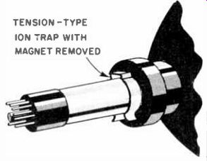
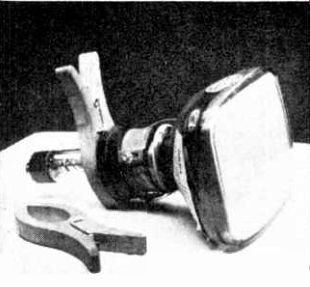
---------- A deflection yoke can be positioned against the flare of a
test CRT without slipping, by using an ion trap as a clamp.
Yoke Clamp
When working with a test CRT on the bench it is very aggravating to have the yoke continually slip down the neck. I have tried various clamps to hold the yoke against the test CRT flare, but found them all inadequate or too time consuming to put in place. After some experimenting I finally found an ideal yoke clamp as follows: Remove the magnet from a tension-type ion trap. This tension clamp can then be clipped on the test CRT neck behind the yoke-and then pushed up against the yoke, as shown. The clamp does the job very well and can be installed in only a few seconds.
CRT Warning
TV receivers with series heaters are not new. But recently some manufacturers have made one important change that may have escaped the attention of many technicians.
On older series string sets accidental burn-out of a CRT heater was minimized by inserting the CRT at the end of the heater string. Recently, the trend has been to move the CRT further up on the string. The first change placed the CRT before the tuner tube heaters to reduce 60 cycle pick-up by the tuner. With this arrangement there was still little danger to the CRT heater as it remained near the low end of the string, as illustrated.
More recently, however, the CRT heater is being connected toward the high end of the string, as shown at left. Consequently, accidentally grounding some point on the heater string, can easily blow the CRT heater, since the voltage on one side of the heater may be as high as 65 volts in some sets. Because of this design trend, a misplaced or accidental ground could prove to be costly.
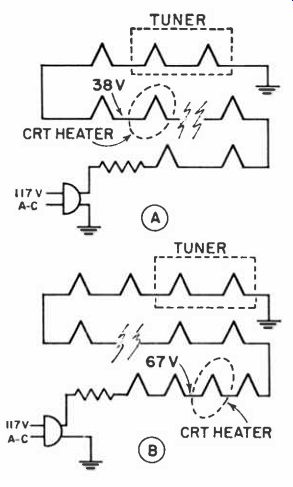
----------- (A)-The CRT has better protection if placed near the low end
of the heater string. (B)-When placed near the high end, an accidental short
increases danger of a CRT burn-out because of higher heater voltage.
CRT Measurements
When voltage and resistance measurements are to be made at the CRT socket and an adapter is not available, I have found the following method to be quick and easy. Cut or scrape a small amount of insulation on the leads going to the CRT socket.
It is a good idea to stagger and position these openings in the insulation to avoid contact with each other, or other parts of the chassis. Clip the leads of a VTVM or VOM and take a reading on the ohms scale, to be certain that a good contact has been established. Switch to the proper voltage scale, turn on the set and take the readings.
Another advantage this method offers, is that the CRT socket may be disconnected, in a parallel heater string set, to note changes of voltage.
Troubleshooting procedure is greatly facilitated, and should help the technician localize troubles in and around the CRT area.
A reasonable amount of care to prevent nicking or cutting the conductors should be observed. A couple of turns of insulation tape should be applied to exposed wire after the tests have been completed. Needle-pointed probes may be used to puncture the insulation, and thus partial stripping is avoided. Ordinary straight pins may be used and the meter's leads clipped directly onto them. If this last method is used, make certain that a good electrical connection is established.
Pix-Tube Seat
When it becomes necessary to carry a CRT, the top surface of a baby's bassinette makes an excellent seat. It will absolutely protect the face from being scratched.
If such a seat is not available, one can be made up easily by stretching some light canvas material over a wooden frame and tacking it down on all four sides. The actual size of the canvas used is 32 in. by 22 in.
The wooden frame, which is 30 in. by 20 in., is made up of lumber 3 in. wide. With the full weight of the picture tube on this cradle, there will be no contact between the canvas and any fiat surface on which the cradle is placed.
Boosting Soft CRT's
When one filament booster is used to restore brightness to an aging CRT, it is often not sufficient if the tube has become too "soft." A simple method of achieving enough improvement to extend the life of the picture tube is to put two CRT boosters in series temporarily. This will give the filaments approximately 3 or 4 additional volts. It is not advisable to leave the two connected any longer than is necessary to bring about the desired improvement. Then one of the boosters is removed. We have found that this procedure straightens out most of the very soft picture tubes.
--------- CRT's with cold-solder filament connections can be permanently
saved by baring the pin's heater wires before soldering.
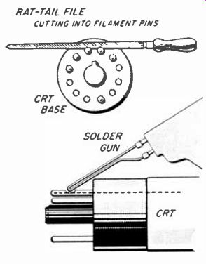
CRT Heater Repair
A high resistance solder joint frequently occurs on CRT pins 1 or 12, causing the heater to open. In some cases we have found new CRT's with insufficient solder or cold joints in the pins-rendering the tubes inoperative. The tube, regardless of age, may be perfect in every respect but lack of heater voltage has made it a useless dud.
After trying many soldering methods we found the following procedure to be the most effective: Using a small fine-cutting rat-tail file and holding the heater pins firmly with long nose pliers, carefully file into the heater pins to a point where the wire protruding from the glass bulb are exposed.
File the wire itself slightly-just enough to produce a clean raw surface. Apply a small amount of rosin core solder to the exposed area with a soldering iron, allowing solder to flow into the opening until the area is just filled. When the job is done in this manner there is little chance of a second failure because of a poor joint.
Yoke Support
The problem was to make the yoke stay firm against the bell of the 8XP/8YP test CRT. I solved it by devising a neck stock block. The device is made out of a piece of fairly hard wood about 4" square and 1" wide. Find the center of the 4" square face and drill a hole slightly smaller than the test tube neck diameter. Then cut from side to side and through the center of the hole as shown. Mount a 1" hinge so that the device can be opened and closed.
Fasten two 1" angles on the side opposite the hinge. Tighten the upper angle but not the lower one. The lower angle should be free to rotate around its mounting screw. Before mounting the top angle, cut a slot from the hole to one of its sides.
Insert a 6-32 machine screw through the bottom angle and lock it with a nut.
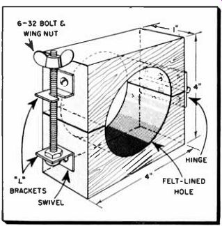
------- Stock block supports yoke on test CRT.
-------- CRT rejuvenator.
Add a wing nut, and line the opening with a piece of felt or cloth.
The wing nut can be loosened and swung aside to open the block. The block can then be mounted around the neck of the tube. Use common sense when tightening the wing nut.
Excessive pressure can do damage.
If it appears to be too hazardous, a rubber band slipped over the angles can be used instead.
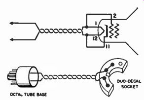
CRT Rejuvenator
This CRT rejuvenator may be used with any regular tube checker. The same voltage used to energize the filament also appears between the grid and cathode of the CRT. Grid current will flow during the positive alternation. The duty cycle is sufficiently short to prevent damage to these elements. The only parts required are a CRT socket, and about 6 feet of 2 conductor wire. Wiring is self explanatory. Operation is simple.
Tubes may be rejuvenated in the set or on the bench. Connect the 2 wires to the filament terminals on the tube tester, and the socket to the CRT. Apply the following voltages, for the approximate time as indicated: 12.5-v. for 20 seconds, and 10.0-v for 20 minutes, or less. The leads going to the tube checker may be connected to an old tube base, and plugged into the checker. Another servicer has submitted the following item dealing with this same subject. -Ed.
Instead of using the tube checker, which may not be available when, in the customer's home, merely hookup a pair of clip leads between the CRT and the filament supply. One lead, from pins 1 and 2 to one side of the 6.3-v. filament supply, and the other lead from pins 11 and 12 to the other side.
CRT Base Replacement
I have fiddled with CRT bases trying to get them back on the neck of the tube when they have inadvertently broken off. I have tried cardboard templates and extension wires. When I did succeed I had no confidence in the electrical connection, not being able to see if the leads had tacked on to the base pins.
To save time and patience, clean out the base, remove the solder in the pins and break away a portion of the base opposite the area where the pins are located. A pair of diagonal cutters can be used to carefully chip away the material. It is now possible to see the leads and guide them accordingly. Solder and check the connections. The base can then be cemented to the tube. If not too much material is chipped away, there will be sufficient area to establish a firm support. A layer or two of tape will cover the opening, and reinforce the base connection.
------ Window formed in base of CRT to inspect connections and facilitate
replacement.
Base and Rebase
As a result of heat, age and handling, tube bases become separated from their glass envelopes and electrode leads. It's easier to get a Camel ( African or North Carolinian)
through the eye of a needle than it is to get all of these errant wires back into their proper base pins at the same time. Loss of time and patience often dictate junking the dismembered tube. But with CRT and other expensive tubes and tubes for which no replacement is available, I use this shop kink. Shorten leads to approximately half the original length and form a small hook on the end of each lead. Connect 10" lengths of hookup wire to these leads using a hook joint. Solder and if desirable use spaghetti. Thread lengthened leads through the appropriate pin in the base. Keep the joint as small as possible and pre-tin the wire to facilitate soldering into the tube base.
Use glue or cement, slide tube base home, bend wire over pins, clip excess and solder.
CRT Spots
Most spot eliminator circuits for receivers with magnetic-focus type picture tubes utilize a switch in the brightness control circuit to defocus or extinguish the beam when the receiver is turned off. Occasionally the technician gets a request to eliminate this spot or afterglow on the screen of a receiver which does not have the spot eliminator switch. Connect a 500 megohm resistor between the second-anode lead and the chassis.
In most cases the trouble can be eliminated without taking the chassis out of the cabinet.
Some of the picture tubes used in the latest TV receivers are of the straight-gun type (do not use a beam bender) and have a high-capacity rating. These two characteristics increase the need for observance of correct service procedures at all times while checking or repairing the receivers. It is especially important that the sweep circuits should never be disabled while the picture tube is in the circuit, or damage to the phosphor screen may result. The screen damage may appear as a burn or a chip in the phosphor and will usually be located near the center of the screen. The damage can occur in twenty or thirty seconds and therefore does not allow for the margin of error in service procedures which could be tolerated with the older picture tube types. The overall improved characteristics of these new picture tube types result in greatly improved performance, and it is therefore desirable to use them. Since the necessary service procedure includes standard practices normally recommended for the service of all receivers, no new problem is presented. However, turn the set off before pulling tubes in the oscillator or sweep circuits of the chassis. This includes other tubes which might disable the oscillator or sweep circuits (damper, sync, or control tubes). Do not unplug the yoke from a chassis while the receiver is turned on. Disconnect the second anode lead (high voltage) and discharge the second anode of the picture tube to ground before turning on a receiver which has the yoke disconnected or removed from its normal position on the picture tube neck.
Do not trust to luck in switching tubes. Picture tube damage could develop during the short time required for the tube to be replaced and heat up to its normal operating condition.
CRT Focus Checker
Many manufacturers use a jumper strap on the CRT base for focus adjustment. This jumper is placed between pins 6 and 2 or between 6 and 10, whichever provides best focus. The change in focus in each position of the jumper is usually quite small, and selecting the best location of the jumper is difficult as the set is shut off during the jumper change. By constructing the unit shown (see above), the best position of the jumper can be readily determined as both jumper positions can be tried with a flick of the switch.
The cost of construction can be made very low by using a discarded CRT brightener. The switch positions should he marked with the respective CRT pin numbers.
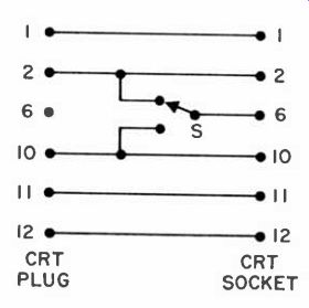
--------- A low-cost time-saving device selects proper CRT pin for focus
jumper strap.
Burned Phosphors
Whenever a fixed test pattern such as is produced by a color-bar generator is used for testing a color TV receiver, care should be taken to prevent damage to the phosphor coating on the kinescope. When the receiver is on test for a considerable period of time, with color bars, the brightness and color controls should be set for a low level of brightness to prevent "burned in" bars on the face of the CRT. Normal usage of the tube has the effect of aging the phosphors so that they are less susceptible to burns from a stationary pattern. It is recommended, therefore, that new tubes should not be operated with a fixed pattern of high intensity for more than 15 minutes. In the event that a kinescope has a burn in a localized area it can normally be scanned off in a few hours. This may be done as follows. Tune in a strong b&w signal from a TV station and turn up the brightness and contrast controls. Adjust the vertical hold control until the picture rolls continuously.
Faulty CRT Prongs
I frequently find poor connections on the pins of picture tubes, especially filament pins. Insert-mg a piece of fine wire in the pin when resoldering establishes better contact, eliminating this trouble completely.