No better way can be found to learn the inner workings of a television receiver than to build one. The result of such a project can be a receiver useful for pre-installation surveys, laboratory experiments, demonstrations, and for entertainment in the home.
Included in this section are the schematic circuit, parts list, and chassis layouts for a television receiver which can be operated with non-ion trap 10, 12, or 15 inch magnetic picture tubes.
If the builder wishes to use an ion trap picture tube, permanent magnet ion traps are available.
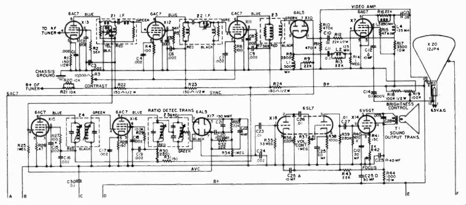
Figure 1
The schematic circuit for all sections of the receiver, except the RF tuner, is shown in Figure 1. The audio and video circuits use pre-aligned IF transformers which are tuned for IF carrier frequencies of 21.9 Mhz. and 26.4 Mhz., respectively.
It is difficult to construct and align an RF tuner that will perform well at the high television frequencies without proper test equipment. Several pre-aligned RF tuners can be purchased which are built up as complete assemblies. The tuner that is selected should provide a sound IF frequency of 21.9 Mhz. and a video IF frequency of 26.4 mhz. The circuit for coupling the mixer stage in the RF tuner to the first video IF stage is shown in Figure 2.
The main chassis contains all the parts shown in the schematic diagram of Figure 1. Figure 3 shows the layout of parts on the skirts of the chassis. A bottom view of the chassis is shown in Figure 4. The RF tuner assembly is mounted in the space indicated in the upper left hand corner. The location of terminal strips for mounting the small parts is also shown. The socket for the 8016 high voltage rectifier should not be mounted directly on the chassis, but should be supported on stand-off insulators.
It is suggested that a metal shield be built around the high voltage tube and transformer.
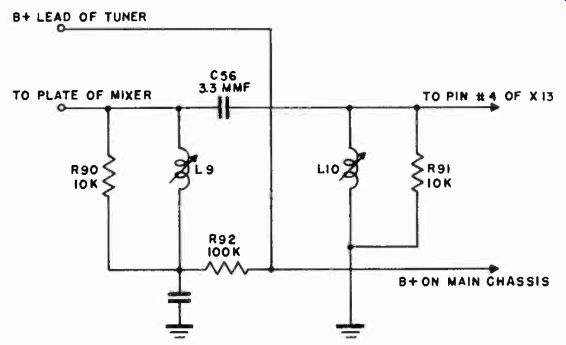
Figure 2.
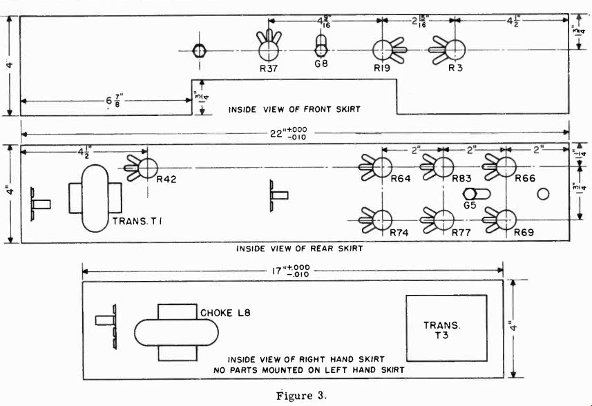
Figure 3.
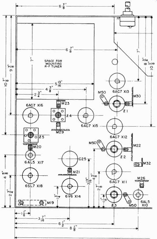
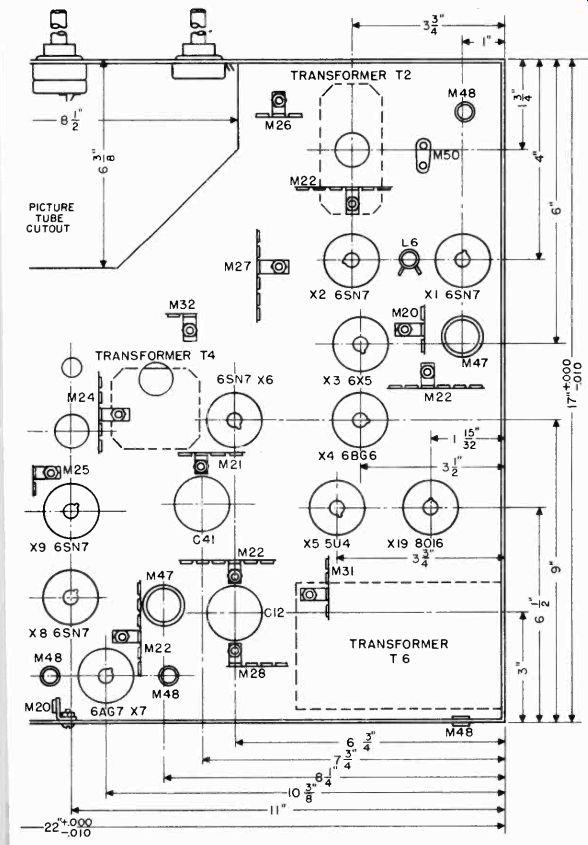
Figure 4.
---------
R1, R22, R23, R24, R28,R31, R41-150 ohms, watt R2, R5, R7, R 50, R 5 7, R 73 , R 78-56, 000 ohms, i watt
R3-Potentiometer, 10,000 ohms c bias taper, 1-1/4" shaft (contrast control)
R4, R6, R81, R92-100 ohms, i watt R8-3300 ohms, i watt R9, R 12, R13 , R 16, R 3 2, R3 3, R43, R46, R4 8 R53,R72-22,000 ohms, ? watt R10, R11,R40,R47, R51,R56,R75-470, 000 ohms, ''z watt R14, R25,R34,R58, R63, R65,R68,R89-1.0 meg., ? watt
R15,-47,000 ohms, 1 watt R17-3,500 ohms, 10 watt R18,R27,R29,R49,R62,R71-100,000 ohms, watt R19-Potentiometer, 100,000 ohms 1/2 watt linear taper, with switch, 1-1/4" shaft (brightness control)
R20,R21, R59,R60,R61,R86, R90, R9110,000 ohms, 1 watt R28,-47 ohms, watt R30-2200 ohms, z watt R35-3.3 meg., z watt R36,R39-220,000 ohms, i watt R37-Potentiometer, 1 meg., i watt audio taper with switch, 1-1/4" shaft (volume control)
R38,R52-1000 ohms, watt R42-Potentiometer, 2,000 ohms-linear taper, screw driver slot (focus control)
R44-1000 ohms, 10 watt R45,R55-2200 ohms, e watt R54,R67-4700 ohms, i watt R64-Potentiometer, 1 meg.-linear taper, screw driver slot (vertical hold control)
R66-Potentiometer, 2 meg.-linear taper, screw driver slot (vertical size control) R69,R83-Potentiometer, 5,000 ohms linear taper, screw driver slot (vertical linearity control, horizontal linearity control)
R70,R87,R88-470 ohms, watt R74,R77-Potentiometer, 100,000 ohms-linear taper, screw driver slot (horizontal hold control, horizontal drive control)
R76-680,000 ohms, i watt R79,R80-190 ohms, 1 watt R82-10,000 ohms, 10 watt R84-3.3 ohms, z watt R85-10 ohms, 1 watt Cl-C9,C15-C19,C24,C32,C48-.002 mid., 600 volts, paper C 10, C 11, C 14, C3 0, C38, C40, C43, C50-0.1 mid., 600 volts, paper C12,C25,C41-40-30-10/450-10/25 electrolytic (can, negative)
C13,C31,C39,C42,C51,C54-.05 mid., 600 volts, paper C20,C21,C44,C46,C49-150 mmf., 500 volts, ceramic or mica C22-9 mid., 50 volts, electrolytic, pigtail leads C23,C26,C27,C29,C47-,01 mid., 600 volts, paper C28-.005 mid., 600 volts, paper C33-C37-.005 mid., 600 volts, paper C45-500 mmf., 500 volts, mica C52-.0012 mid., 10,000 volts, ceramic C53-.035 mid., 600 volts, paper C55-50 rand., 500 volts, ceramic C56-3.3 mmf., ceramic L1-500 mh.. pigtail leads-peaking coil Transvision 0-319 L2,L4-125 mh., pigtail leads-peaking coil-Transvision 17 L3-250 mh., pigtail leads-peaking coil Transvision 16 L5-Deflection yoke-RCA 201D1 L6-Horizontal linearity control-RCA 201R3 L7-Focus coil-RCA 202D1 or Stancor FC 10 LB-4h, 250 mil. filter choke L9-Balancing coil-Transvision 0-365 Lí0-Balancing coil-Transvision 0-365 T1-Output transformer-6V8 to V.C. T2-Vertical blocking oscillator transformer-RCA208T2 T3-Vertical output transformer-RCA 2041'2 T4-Horizontal blocking oscillator transformer 0-307 T5-Horizontal output transformer RCA 211T1 T6-Power transformer-400-0-400v225ma., 5v-3a, 6.3v-10a, 6.3v-1.75a.
Z1-First video IF transformer Transvision 175 Z2-Second video IF transformer Transvision 174 Z3-Video detector IF transformer Transvision 176 Z4-First sound 1-f transformer Transvision 318 Z5-Ratio detector IF transformer Transvision 317 X1,X2,X6,X8,X9-6SN7 X3-8x5GT X4-6BG6 X5-5U4G 5V4G X7-6AG7 X10,X17-6AL5 X11,X12,X13,X15,X16-6AC7 X14-BV6GT
-------------