10-1 In the past, a signal generator, multimeter, and tube checker have been considered adequate test equipment for service shops. Such instruments as oscillographs and vacuum tube voltmeters, while extremely useful, were definitely not necessities.
With the advent of television, the three basic test instruments are no longer adequate. New test equipment, generally of a highly specialized nature, is required. In this section, the instruments required for the troubleshooting and adjustment of tele vision receivers are described.
The instruments available for testing and adjusting television receivers can be divided into two groups: (1) those which are essential and (2) those which, although not essential, will simplify maintenance procedures and save time.
The following instruments are generally considered essential:
1. Cathode-Ray Oscillograph.
2. Sweep Frequency Signal Generator.
3. Audio Frequency Signal Generator.
4. R-F Frequency Signal Generator.
5. Vacuum Tube Voltmeter and Probe.
6. Multimeter.
7. Kilo-voltmeter, or High-Voltage Probe.
In addition to the above instruments, the following are useful:
1. R.F. Probe for Oscillograph.
2. Square Wave Generator.
3. Oscillograph Voltage Calibrator.
4. Grid Dip Meter.
5. Q Meter.
6. R-C Bridge.
7. Crosshatch Generator.
Before a piece of test equipment is selected, its specifications should be examined carefully. The requirements for each type of instrument are outlined in this section. The unit chosen should meet, and if possible exceed, the specifications given. In addition, each new instrument selected should supplement the abilities of those instruments already in the possession of the purchaser. For example, a high voltage probe may be purchased instead of a kilo-voltmeter if a suitable high resistance voltmeter is available. Other things which should be noted are the construction, accuracy, versatility, and freedom from obsolescence of the equipment under consideration.
CATHODE-RAY OSCILLOGRAPH
10-2 One of the most versatile and useful instruments for servicing all sections of the television receiver is the cathode-ray oscillograph or, as it is often called, the scope or CRO. The oscillograph is used to examine voltage waveforms in the horizontal and vertical sweep circuits. It can be used to locate the causes of such video amplifier faults as clipping due to improper bias and loss of amplification due to faulty components.
The causes of improper operation of synchronizing-pulse "clipper" stages can easily be located with the oscillograph, and excessive hum from power supplies is quickly identified, both as to amplitude and frequency.
One of the most important uses of the cathode-ray oscillograph is in the visual alignment of tuned circuits.
A block diagram of a typical oscillograph is shown in Figure 1.
This oscillograph employs an electrostatically focused and deflected cathode-ray tube as do all oscillographs intended for television servicing. Shown in the block diagram are the horizontal (X) and vertical (Y) amplifiers and gain controls. In addition, the oscillograph is equipped with vertical and horizontal positioning controls and intensity and focus controls.
The vertical amplifier amplifies the signal which is to be observed. The output of the amplifier is fed to the vertical deflection plates of the cathode-ray tube. The gain control is provided in the vertical amplifier for adjusting the pattern to a convenient size. In some oscillographs, provision is also made to permit connecting the vertical amplifier to a calibrating voltage source in order to measure the amplitude of the applied waveform.
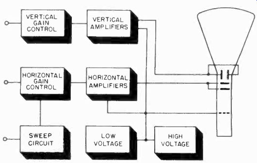
Figure 1. Block diagram of cathode-ray oscillograph.
The output voltage of the horizontal amplifier is used to deflect the electron beam from left to right, in accordance with the voltage applied to it. An attenuator of some type is provided, so that the pattern width may be adjusted to a convenient size.
Normally a sawtooth voltage is fed to the horizontal amplifier from the built-in sweep circuit, so that the voltage applied to the vertical amplifier is plotted as a function of time. The sweep circuit is usually equipped with coarse and fine frequency controls for adjusting the sawtooth frequency to the desired value.
In addition, a synchronizing control is provided for synchronizing the sawtooth frequency with the signal being examined, the 60-cycle power line, or an other external source. The oscillograph is also equipped with high and low voltage power supplies which provide operating potentials for the amplifiers, sweep circuits and the cathode-ray tube.
10-3 The Vertical and Horizontal Amplifiers. The vertical amplifiers of oscillographs suitable for television servicing usually consist of one or more single ended stages of amplification, working into a push-pull deflection amplifier.
Since an ordinary resistance-capacitance coupled amplifier stage does not provide sufficient bandwidth, some form of low and high frequency compensation must be used. High frequency compensation is secured by placing a suitable inductance in the plate circuit of an amplifier as shown in Figure 2. Its function is identical to similar inductances utilized in the video amplifiers of television receivers.
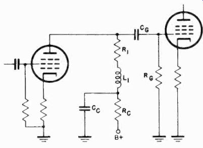
Figure 2. Oscillograph amplifier with high frequency compensation.
Low frequency compensation takes the form of resistor Rc and Capacitor Cc. These components, and Cg and Rg, are chosen for optimum low frequency response.
To permit the study of signals of various amplitudes, some form of input attenuation must be used. Special circuits are necessary to obtain the required high impedance input and freedom from frequency discrimination. If the signal were coupled to the amplifier input through a high resistance potentiometer, a suitably high input impedance would be obtained, but frequency discrimination would result. If a low resistance potentiometer were used, the frequency discrimination would be avoided, but the input impedance would be too low. The problem is solved by the addition of a cathode follower input stage, as shown in Figure 3.
A stepped frequency compensated input attenuator is used. Intermediate gain adjustments are made using a low resistance potentiometer located in the cathode follower output.
It is difficult to obtain sufficient voltage to deflect the cathode-ray tube if single-ended deflection is employed, and therefore most high-frequency oscillographs have push-pull output stages.
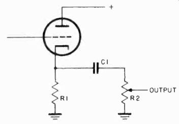
Figure 3. Cathode follower input stage.
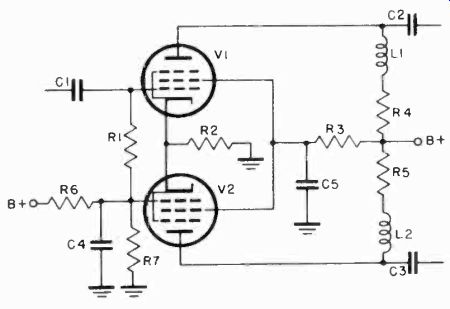
Figure 4. Cathode-coupled output stage.
Almost all oscillographs having push-pull output stages use the cathode-coupled, self-inverting output stage shown in Figure 4.
In this circuit, the signal is applied to the grid of V1, causing an in-phase voltage to appear across the common cathode resistor R2. Since the grid of V2 is grounded by condenser C4, the grid-cathode voltage of V2 is equal to the signal voltage across R2. However, since a positive voltage on the cathode is equivalent to a negative voltage on the grid, the plate voltage of V2 is 1800 out of phase with the plate voltage of V1. By using a large value of common cathode resistor, the amplitudes of the two outputs will approach each other within a few percent. Since such a large cathode resistor would result in entirely too large a negative bias on the tubes, a small amount of positive bias is placed on both grids through the network consisting of R6 and R7.
The design of the horizontal amplifier of a cathode-ray oscillograph is similar to that of its vertical amplifier, except that the gain of the horizontal amplifier is usually lower, and the frequency response not as great. The horizontal amplifier receives its signal from either an external sweep signal, such as that provided by most wobbulators, or from an internal sawtooth generator. To provide blanking of the return trace, an out-of phase signal from the horizontal sweep amplifiers is often applied to the grid of the cathode-ray tube.
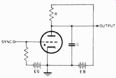
Figure 5. Gas triode sawtooth generator.
10-4 Sawtooth Generators. The simplest type of sawtooth generator utilizes a gas triode, as shown in Figure 5. In this type of circuit, when B voltage is applied, condenser C starts charging through series resistor R. When the voltage across the condenser reaches the ionization potential of the gas triode, the tube suddenly conducts and rapidly discharges the condenser.
A sawtooth voltage is thus generated whose frequency is determined by the size of the resistor and condenser, the plate voltage, and the ionization potential of the tube. Since the ionization potential is controlled by the grid bias of the tube, the frequency of oscillation can be determined by a signal applied to the grid.
For example, the sawtooth oscillator can be synchronized by the same voltage that is applied to the vertical amplifier by feeding this voltage to the grid of the gas triode.
A recurrent sawtooth, such as that produced by the circuit just described, is a suitable sweep voltage waveform if the signal to be examined is recurrent in nature. If it is irregular in occurrence, or if a small portion of it is to be spread out and examined in detail, a driven, or triggered-sweep sawtooth generator is required. Such a generator produces one sawtooth of voltage each time it is triggered. Hence, the start of the saw tooth sweep always occurs at the same time as the signal to be viewed. It is possible to convert the recurrent sawtooth generator into a triggered-sweep generator by modifying the circuit as shown in Figure 6.
In this circuit, the cathode potential of the diode is set to such a value that the diode will conduct at a slightly lower plate-to ground potential than the triode. Thus, when the sweep condenser C charges to the potential of the diode cathode, the diode will conduct and prevent the condenser voltage from reaching the ignition potential of the gas triode. However, if a positive sync signal is momentarily impressed on the triode grid, it will lower the triode ignition potential below the voltage of the diode cathode, allowing the triode to conduct and discharge the condenser. The condenser will then charge, through the resistor, until it reaches the diode cathode potential again, where it will be "clamped" by the diode. During this time, the spot on the oscillograph screen has made a fast retrace from right to left, and then a single sweep from left to right, producing the required single sweep.
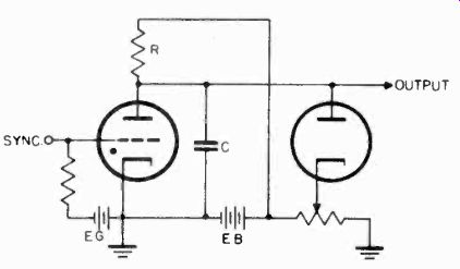
Figure 6. Gas triode circuit for generating driven or triggered sweep.
10-5 The Cathode-Ray Tube and High Voltage Supply. The cathode-ray tubes used in present day cathode-ray oscillographs are of the electrostatically-focused, electrostatically-deflected type.
A P-1, green-fluorescent, medium persistence screen is employed instead of the P-4 screen employed in television picture tubes.
The power supplies used in oscillographs are somewhat similar to those used in television receivers. A typical supply for a high gain oscillograph is shown in Figure 8. It will be noted that the high voltage winding is an extension of the low voltage winding on the single power transformer used. Half-wave rectification and a two section filter consisting of C28, C29, C31, R49, and R55 is used.
The low voltage supply is regulated in order to minimize the , effects which line voltage variations have upon the deflection amplifiers. The regulated supply also has very little ripple, a necessity in high gain instruments.
10-6 Oscillograph Requirements for Television Servicing. The many uses to which the oscillograph may be put in the maintenance of television receivers call for such wide versatility that few oscillographs meet all service requirements. For television servicing, an oscillograph should meet the following specifications:
1. High gain The vertical amplifier should have a sensitivity of at least 25 millivolts RMS per inch in order to permit stage-by-stage alignment of IF amplifiers in conjunction with a sweep frequency signal generator, or wobbulator. If an overall alignment procedure is used in which the oscillograph is connected to the output of the IF amplifier system, a sensitivity of 0.1 volts RMS is adequate.
2. Good 60-cycle square wave response Since most sweep frequency signal generators operate at 60 cps, the vertical amplifier should have good 60-cycle response to pass the wobbulated signal. Good low-frequency response is necessary, too, for observing the 60-cycle vertical sweep and sync signals in the receiver. If the instrument is to be used with a square wave generator to adjust video amplifier stages, it should have good square wave response down to 30 cycles.
3. Good high-frequency response Vertical amplifier response extending to 100 khz is adequate for alignment work with a wobbulator. If the oscillograph is used for examining video and horizontal sweep signals, and for checking video amplifiers by means of a high-frequency square wave, the response should extend to at least 2 Mhz, and preferably to 4 Mhz.
4. Low input capacity to vertical amplifier This is required when checking horizontal sweep circuits and video amplifiers.
If the input capacity of the oscillograph is too high, the instrument will distort the response of the circuit it is being used to test.
The input capacity should be less than 15 mmf.
5. Suitable tube size For most television applications, 3-inch or 5-inch tubes are suitable.
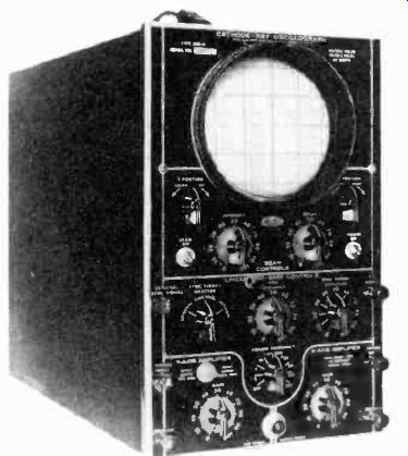
Figure 7. The Du Mont Type 208B Cathode-Ray Oscillograph.
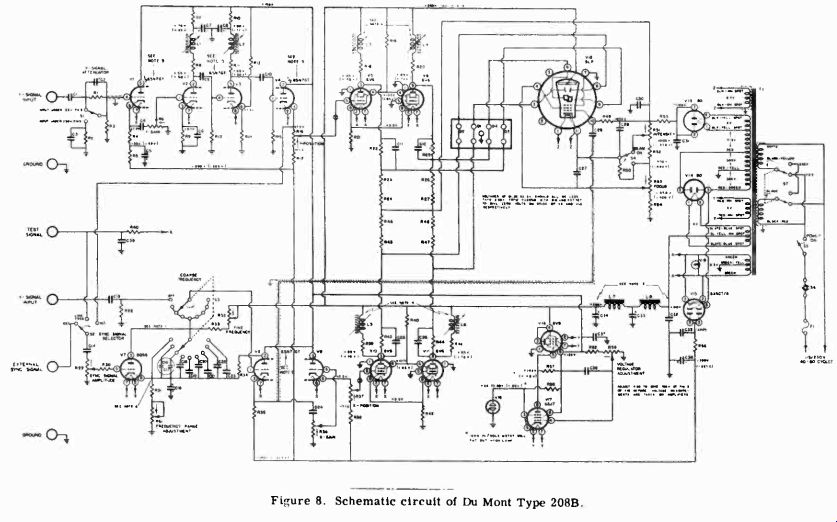
Figure 8
10-7 The Du Mont Type 208B Cathode-Ray Oscillograph. The Du Mont Type 208B Cathode-Ray Oscillograph, shown in Figure 7, is a typical 5-inch instrument. It has a vertical sensitivity of .01 volts RMS/inch, and a frequency response uniform within 10% from 2 hz to 100 khz, at all positions of the gain control.
A schematic diagram of the 208B is shown in Figure 8. A capacity-compensated input attenuator feeds a cathode follower, V1, which has a low impedance gain control in its cathode circuit. This circuit eliminates frequency discrimination in the low-impedance gain control. Tubes V2 and V3 are high-frequency compensated amplifier stages, which have sufficiently large grid resistors and coupling capacitors to give the required low-frequency response. The signal is then fed to another cathode follower, V4, whose output is directly coupled to the two output tubes V5 and V6. V5 and V6 feed separate vertical plates of the cathode-ray tube V12, and provide balanced deflection.
R16, which changes the dc bias on V5 and V6, serves as a positioning control.
The horizontal amplifier employs two cathode followers, V8 and V9, which serve the same function as Viand V4 in the vertical circuit. The horizontal amplifier output stage is identical to the vertical amplifier. A gas triode, V7, is employed in a standard sawtooth sweep circuit, with a range of 2 hz to 50 khz.
The power supply of this instrument is necessarily more complex than those found in lower gain oscillographs. A full wave rectifier, V14, feeds a degenerative-type voltage regulator composed of V16, V17, and V18. The voltage regulator prevents line voltage variations from affecting the operation of the deflection amplifiers. A half-wave rectifier, V15, is used to supply a negative voltage for the cathode followers, so that a large cathode resistor may be used without having excessive bias.
An additional half-wave rectifier, V13, is used to supply the accelerating voltage for the cathode-ray tube.
Because of its high gain, good low-frequency response, and extended high-frequency response, this instrument is excellent for most television work. The Type 208B maybe used for visual alignment of individual IF stages, and for troubleshooting the sync and sweep circuits. Its high frequency response is not adequate for checking the high frequency square wave response of video amplifiers.
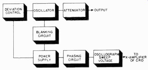
Figure 9. Block diagram of fundamental frequency wobbulator.
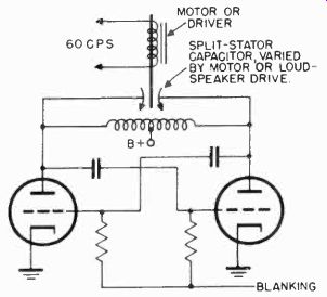
Figure 10. Variable capacitor circuit for wobbulator.
SWEEP FREQUENCY GENERATOR
10-8 The sweep frequency generator, or wobbulator, is used to align the wide-band RF and IF stages of the television receiver. While it is possible to adjust the tuned circuits of a video IF amplifier by using a signal generator and a voltmeter, and checking many points along the curve, the time and labor involved in this method is considerable.
There are two types of sweep frequency generators: (1) those in which the oscillator operates directly at the desired output frequency (or a subharmonic of it), and (2) those in which the output frequency is obtained by mixing the outputs of two separate oscillators together to obtain a beat frequency in the desired range. A block diagram of a fundamental type wobbulator is shown in Figure 9. In the fundamental frequency type wobbulator, an oscillator operating at the desired frequency has its frequency varied periodically, by one of several methods.
A blanking circuit is often provided to disable the oscillator during the deviation cycle to produce a zero base line. A sweep voltage which is properly phased to move the cathode-ray oscillograph beam in synchronism with the frequency deviations of the oscillator is usually built into the wobbulator.
10-9 Generating the Sweep Frequency. In order to vary the frequency of most oscillators, it is necessary to vary the reactance of some part of the tuned circuit. Commercial wobbulators employ one of four methods to generate sweep frequencies: (1) a rotating capacitor, (2) a vibrating capacitor, (3) a vibrating inductor, or (4) a reactance tube.
Rotating capacitor units utilize 1800 or 3600-rpm synchronous motors, driving small, ball hearing capacitors. Most test equipment manufacturers have discarded this method of frequency modulating an oscillator in favor of other, less expensive, and more flexible methods.
Vibrating capacitor units employ driver units, similar to PM loudspeaker drivers, to vary a split-stator concentric capacitor.
The capacitor is used in a push-pull oscillator circuit, as in Figure 10. The voice coil is normally driven with a 60-cycle voltage, so that one complete excursion of frequency, from the lower limit to the upper limit and back, takes place in one sixtieth of a second.
The vibrating inductor method employs a driver unit similar to the vibrating capacitor type. A disk of metal, instead of a capacitor, is mounted on the vibrator. The oscillator coil is wound in a spiral shape, and the metal disk is located close and parallel to the coil, so that it acts as a closely coupled shorted turn. As the metal disk is vibrated toward and away from the coil by the driver unit, the coupling varies and therefore the effective inductance of the coil varies, producing the required frequency modulation. The coil may be used in either a push-pull or single-ended oscillator circuit.
All of the above methods of frequency modulation utilize an electro-mechanical method of varying the oscillator frequency.
It is possible, however, to produce the effect of a varying inductance or capacitance by electronic means, using a reactance tube. When a reactance tube is used in a wobbulator, a 60-hz sine wave is fed into its grid, causing the oscillator frequency to vary at a 60-hz rate.
All of the methods for generating sweep frequencies so far described have the shortcoming of not being able to produce a constant frequency deviation at different center frequencies.
For example, if the sweep oscillator is designed for the alignment of the RF channels in a television receiver, its center frequency must be varied from 54 to 216 Mhz. To properly align each of the 12 channels in this range, the center frequency should deviate plus and minus 5 Mhz. It is difficult to obtain this deviation over a wide range with the sweep generator methods just described. With the methods described, the deviation may be plus or minus 3 Mhz at the lower center frequencies, and as much as 7 or 8 Mhz at high center frequencies. The deviation problem is overcome in many instruments by using a beat method for obtaining the desired sweep frequency range. A block diagram of such an instrument is shown in Figure 11. With this method, the frequency modulated oscillator is operated at a fixed frequency, and an auxiliary oscillator is tuned to obtain the center frequency. The outputs of the two oscillators are mixed to produce a sweep frequency signal at the desired frequency. For example, if the center frequency of the frequency modulated oscillator is 114 Mhz., and the variable oscillator can be tuned from 37 Mhz to 112 Mhz, output may be obtained from 114 + 37, or 151 Mhz, to 114 + 112, or 226 Mhz, with a deviation equal to that of the frequency modulated oscillator.
In order to produce the proper sweep voltage for the oscillograph, a 60-cycle sine wave or a 60-cycle triangular wave (if blanking of the oscillator is not provided) is required to superimpose the forward and return traces. If the oscillator is blanked, either of the above waveforms, or a 120-cycle sawtooth voltage may be used. When sine wave sweep is used, it is usually
fed through a phasing network to allow the sweep voltage to reach its maximum at the same time the wobbulator reaches its maximum output frequency. The same type of network is used to adjust the phase of the blanking voltage. A 60-hz triangular wave is usually produced by integrating a 60-hz square wave voltage formed by clipping a sine wave in a circuit similar to that shown in Figure 12. This circuit includes a tube used to provide blanking voltage for the sweep oscillator.
10-10 Sweep Generator Requirements. The sweep frequency generator must cover a wide range of frequencies if it is to be used for aligning all the amplifiers in a television receiver.
The center frequencies and the deviations which the sweep generator must be capable of producing are listed below.
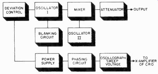
Figure 11. Block diagram of beat frequency wobbulator.
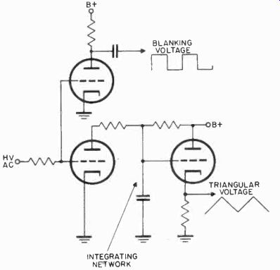
Figure 12. Circuit for generating triangular wave and blanking pulse.
21.5
4.5 Mhz Mhz
+ 500 khz
+ 500 khz
Sound IF amplifiers
Intercarrier sound IF amplifiers
24 Mhz + 5 Mhz
Video IF amplifiers
57 Mhz + 6 Mhz Channel 2 RF amplifiers 63 Mhz + 6 Mhz Channel 3 RF amplifiers 69 Mhz + 6 Mhz Channel 4 RF amplifiers 79 Mhz + 6 Mhz Channel 5 RF amplifiers 85 Mhz + 6 Mhz Channel 6 RF amplifiers 177 Mhz + 6 Mhz Channel 7 RF amplifiers 183 Mhz + 6 Mhz Channel 8 RF amplifiers 189 Mhz + 6 Mhz Channel 9 RF amplifiers 195 Mhz + 6 Mhz Channel 10 RF amplifiers 201 Mhz + 6 Mhz Channel 11 RF amplifiers 207 Mhz + 6 Mhz Channel 12 RF amplifiers 213 Mhz + 6 Mhz Channel 13 RF amplifiers 8.5 Mhz + 500 khz Prewar sound IF amplifiers 12.75 Mhz + 5 Mhz Prewar video IF amplifiers 5 Mhz _+ 5 Mhz Video amplifiers
At the frequencies listed above, the only practical method of carrying the RF voltage from the wobbulator to the receiver is by means of a coaxial cable, since a length of coaxial cable, terminated in its characteristic impedance, has a response which is flat over the frequencies listed. Approximately 500 millivolts of wobbulator RF signal should be available at the end of the cable. For aligning IF amplifiers, and RF sections which are normally connected to the antenna by a coaxial line, the wobbulator should have single-ended output. For aligning RF sections which are normally connected to the antenna with twinlead, the wobbulator should have a balanced-to-ground, push-pull output. An attenuator should be provided to permit varying the output of the wobbulator.
Since few oscillographs have a sweep voltage which can be adjusted to the proper phase, the wobbulator should supply its own sweep voltage. If varying the bandwidth varies the phasing, as it usually does in electro-mechanical wobbulators, a phasing control should be provided.
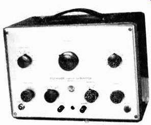
Figure 13. RCA WR-59A Television Sweep Generator.
10-11 The RCA WR-59A Television Sweep Generator. This unit, shown in Figure 13 is an extremely versatile instrument which covers all the intermediate frequencies required for aligning modern television receivers. Frequency modulation is accomplished by means of a vibrating capacitor unit, and both direct and beat frequency outputs are used. For the RF and sound IF channels, where the percentage deviation is small, the oscillator operates directly at the desired output frequency.
Three other ranges of 0 10 Mhz, 5 15 Mhz, and 20 30 Mhz are provided for aligning video IF and video amplifiers. In these ranges, the frequency modulated oscillator sweeps from 80 to 90 Mhz, and an auxiliary oscillator, set at either 80, 75, or 60 Mhz, beats with it to produce the desired output. For the 13 RF channels, balanced output is provided, as required by the RF sections used in most television receivers, while for IF alignment single-ended output is provided.
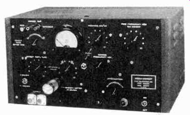
Figure 14. Kay Electric Mega-Sweep.
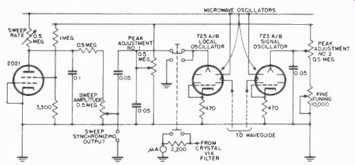
Figure 15. Basic schematic circuit of Mega-Sweep.
When used with an external marker signal generator, this unit meets the requirements for television alignment. The switching arrangement for selecting frequency ranges makes it simple and convenient to operate.
10-12 The Kay Electric Mega-Sweep. The Kay Electric Mega sweep (Figure 14) is a wide-band beat-frequency wobbulator having a bandwidth adjustable up to 30 Mhz with a center frequency adjustable from 50 khz to 500 Mhz. An internal adjustment allows center frequencies up to 1000 Mhz to be obtained. The output across a terminated 50-ohm coaxial cable is approximately .05 volts up to 500 Mhz, and drops somewhat for higher frequencies.
The basic schematic of the instrument is given in Figure 15, showing the two 2K25/723 A-B reflex klystron oscillators and the 2D21 sawtooth voltage generator. The outputs of the two oscillators, which operate in the 10,000 Mhz region, are injected into a special microwave waveguide, where they are mixed and detected by a crystal diode. By mechanically varying the dimensions of the internal cavity of the klystron, their frequency may be varied as much as 1000 Mhz. By varying the repeller voltage, the klystron frequency may be swept as much as 30 Mhz.
This is accomplished by the sawtooth voltage generated by the 2D21 gas tetrode. Attenuation of the RF output voltage is provided by a microwave attenuator which varies the output of the fixed frequency klystron.
The power supply for this unit is regulated to maintain the required voltage stability.
SIGNAL GENERATORS
10-13 The advent of television has imposed much broader and stricter requirements on signal generators, among them wider frequency ranges, increased accuracy, and special output systems adapted for the higher frequencies. The main uses of the signal generator in television are in setting the receiver local oscillator to the correct frequency for each channel, aligning stagger-tuned IF's (which should be given a final touch-up with a sweep frequency signal generator), adjusting sound traps, making sensitivity and stage gain measurements, and providing "birdie" markers to indicate particular frequencies on the response curve obtained with a sweep frequency generator.
Signal generators are also useful for producing linearity bars, which are used to adjust the linearity of the vertical and horizontal sweep circuits.
For television service work, a signal generator must cover the range from the low audio frequencies up to at least 220 megacycles. Because of the nature of the circuits necessary two separate units are normally required, one for the audio frequencies and a second for the higher frequencies. The accuracy requirements are unusually strict, especially at the higher frequencies, where as little as a 1% error in frequency is equivalent to approximately 2 Mhz. For precise alignment work, the signal generator must be either crystal-controlled or crystal calibrated, for ordinary LC oscillators cannot maintain a precise calibration over a period of time.
In the audio and low radio frequency ranges (0-100 khz), two different types of circuits are in wide use, the beat frequency oscillator and the RC oscillator. In the remainder of the radio frequency range (100 khz 230 Mhz)? self-excited Colpitts and Hartley oscillators are used. Crystal controlled oscillators are used in units designed specifically for generating marker signals.
The beat frequency type of signal generator employs two RF oscillators, operating at slightly different frequencies. One oscillator generates a fixed frequency which is heterodyned with the voltage from another, variable, oscillator. The output signal has a frequency equal to the difference between the two oscillator frequencies.
In addition to the two oscillators, an amplifier is provided to bring the beat frequency up to the required voltage level. An a.v.c. circuit is usually employed to maintain the output voltage constant as the frequency is varied. This type of oscillator is used to cover the audio and low IF frequencies.
The RC oscillator can be conveniently made to cover a frequency range of 1 hz to 100,000 hz.
Between 100 khz and about 400 Mhz, ordinary Colpitts or Hartley oscillators are commonly used.
Crystal controlled oscillators are used in units designed to produce marker signals. Since above 12 Mhz, fundamental frequency crystals are not available, overtone or harmonic mode crystals must be used. These crystals have dimensions that would normally permit them to oscillate between 5 and 15 Mhz.
They are cut in such a manner that in the proper circuit they will oscillate at their third, fifth, and seventh harmonics. The circuit used must be designed so that the feedback is provided only at the desired harmonic frequency, and not at the fundamental.
10-14 Signal Generator Requirements. To furnish markers for wobbulator alignment, the signal generator should have a frequency range from about 8 to 240 Mhz. For aligning stagger tuned IF amplifiers, it is desirable to have a 400-cycle modulator in the generator. In checking overall and stage-by-stage gain, a calibrated attenuator, which controls the level of the signal output, is helpful. A terminated coaxial cable should be provided for the signal generator to couple the signal to the receiver under test. An RF voltage of 500 millivolts should be available at the end of the cable.
Usually, two or more generators will be required for completely servicing the receiver. In addition to the RF generator, a wide-range audio oscillator, of the RC or beat frequency type, is useful for checking audio amplifiers and for producing linearity bars. This unit should cover a range of from 20 hz to 200 khz, with less then five percent total distortion. An output of at least five volts should be available.
10-15 The Vacuum Tube Voltmeter. The vacuum tube voltmeter (v.t.v.m.) is used in all sections of the receiver. The extremely high input impedance of this instrument makes it possible to measure voltage at almost any point in a circuit without disturbing the circuit's operation. The v.t.v.m. should have an a-c voltage range of 0.5 volts to 250 volts. The instrument should have a constant input impedance of 10 megohms or more over its entire range.
The instrument should be equipped with a suitable probe to extend its range into the radio frequencies. The RF voltage range should be from 0.5 to 250 volts. Response should be uniform from 10 khz to approximately 250 Mhz. The input capacitance of the probe should not be more than four or five mmf.
10-16 The Multimeter. The multimeter is one of the most used servicing instruments. To provide maximum flexibility, it should have a wide variety of ranges. The following ranges are generally considered adequate.
1. D-C volts 0.5 to 1000 volts.
2. A-C volts 0.5 to 1000 volts.
3. Direct Current i milliampere to 10 amperes.
4. Resistance 2 ohms to 20 megohms.
The d-c sensitivity of the instrument should be at least 20,000 ohms per volt. Many v.t.v.m.'s include some or all of the ranges listed above. If such an instrument is available, a multimeter is not required.
10-17 The Square Wave Generator. A square wave generator and an oscillograph offer the most practical means of checking the frequency response of a video amplifier. Generally, it is sufficient to feed a 30-cycle and 200-khz square wave into a video amplifier to check its performance.
For checking the frequency response of video amplifiers, therefore, the square wave generator should have a frequency range extending from 30 cycles to 200 khz. The square wave generator can also be used to produce linearity bars and, if available, is preferable to a sine wave signal generator. For checking video amplifiers, an output of at least 2 volts peak-to peak is required. To produce linearity bars, 10 volts peak-to peak is necessary.
10-18 Detector Probe. In order to align individual IF amplifier stages using an oscillograph and sweep generator, some form of detector probe is necessary. This probe is connected to the output of the stage being aligned. It detects the output signal before it is fed to the oscillograph.
Most of the probes designed for use with vacuum tube voltmeters are suitable for use with an oscillograph. Probes which use crystal rectifier units are preferred because they do not require provision for heater supply. The circuit of a suitable probe is shown in Figure 16. The components should be mounted in a shielded tube. A length of coaxial cable should be provided for connecting the probe to the input terminals of the oscillograph.
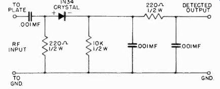
Figure 16. Probe detector.
10-19 The Voltage Calibrator. The voltage calibrator is a very useful accessory for use with the oscillograph. It enables the technician to determine the peak-to-peak voltage of any waveform appearing on the oscillograph screen. Since many television receiver manufacturers give this data for all the important points in the sweep and video circuits, measurement of the voltages at these key points in the receiver makes it possible to quickly locate faulty circuits and components. Commercial calibrators use either a sine or square wave voltage, of known adjustable magnitude, for measuring the amplitudes of unknown signals.
The voltage range that the calibrator should have is determined at the low end, by the maximum sensitivity of the oscillograph, as there is no need for calibrator voltages corresponding to less than a quarter-inch deflection on the screen. The maximum output voltage of the calibrator should be at least 100 volts. The instrument should be calibrated to an accuracy of at least five percent.
10-20 The Grid Dip Meter. The grid dip meter is a very useful instrument for troubleshooting high frequency circuits. It can be used as an indicating wavemeter to identify the frequency to which an oscillator is tuned, or it can be used to identify the frequency to which any circuit in a television receiver is tuned, even if the receiver is not operating. The grid dip meter is actually a wide range oscillator whose mechanical design is so arranged that it can be easily coupled to a circuit. When the circuit is tuned to the same frequency as the grid dipper, energy is absorbed from the dipper. The frequency to which the circuit is tuned is indicated by a dip in the reading of a meter, which is connected to the dipper, as it is tuned through the circuits resonant frequency.
For television work the frequency range of the grid dipper should extend from below 4 Mhz to about 240 Mhz. Usually, a switch is provided to disconnect the oscillator plate voltage, so that the tuned circuit and grid-cathode-meter circuit may be used as a calibrated wavemeter to check spurious responses of oscillators. The instrument can also be used to check resonant frequencies of antennas, or the capacities of unknown capacitors.
10-21 Q-Meters. In all tuned amplifiers, performance depends not only upon the inductances of the coils used, but also upon their Q, which is equal to Xl/R. In high frequency circuits, the Q of the coil is very critical.
If a coil must be replaced in an RF, IF, or video amplifier of a television receiver, it is often helpful to use a Q-meter to check the replacement coil, or to help wind one of equivalent value.
10-22 Resistance-Capacitance Bridges. The technician will often find it necessary to measure resistance or capacitance values more accurately than is possible with an ohmmeter or capacitance meter. In such cases, the required accuracy may be obtained by measuring the component on a resistance-capacitance bridge. This type of instrument is capable of measuring the values of capacitors, resistors, and the turns ratios of transformers. In addition, insulation resistance measurements can be made, and electrolytic condensers may be checked for excessive leakage current at rated working voltage with such an instrument. The following ranges are adequate: Capacitance from 5 mmf to 200 mf. Resistance from 5 ohms to 20 megohms.
10-23 Kilovoltmeter and High Voltage Probes. A high voltage voltmeter with a range to 30 kv is required to check and adjust the various types of power supplies which furnish the accelerating potential to the picture tube. Since most high voltage power supplies used in television receivers delivers only a few hundred microamperes, the high voltage meter should not draw more than 50 microamperes for full scale deflection.
Most vacuum tube voltmeter and volt ohm-milli-ammeters have a maximum voltage range of 2 kv to 5 kv. It is possible to extend the range of these meters by using a high voltage probe.
The probe contains a multiplying resistor which is inserted in series with the meter and increases its internal resistance, thereby raising the voltage range which the voltmeter can handle.
A probe should be used only if the voltmeter available has a sensitivity of 20,000 ohms per volt or more.
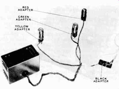
Figure 17. Philco Crosshatch Generator.
10-24 Linearity Signal Generator. Several instruments are manufactured for the specific purpose of checking and adjusting the linearity or the vertical and horizontal sweep circuits.
These instruments are known as bar generators, or crosshatch generators. They produce about 15 to 40 horizontal and vertical lines on the receiver screen or, in some cases, just dots representing the junctions of the bars. It is necessary only to adjust the receiver linearity controls until the bars are equally spaced on the screen to obtain linear sweep.
The Philco Model 5072 Crosshatch Generator, shown in Figure 17 is designed to receive its operating voltages and synchronizing signals from the receiver under test. A special harness, made for the particular receiver, plugs into the receiver and feeds synchronizing, plate, and filament voltages to the crosshatch generator. The circuit diagram of the unit is shown in Figure 18. V1 and V3 are the vertical and horizontal control tubes, while V2 and V4 serve as oscillators and shapers.
Normally, the second half of each control tube is cut off by a large cathode bias voltage, and hence does not affect the oscillators. Negative pulses, obtained from the receiver sync circuits, are amplified and fed to the control tubes as short positive pulses, causing them to conduct momentarily and load the oscillator down heavily enough to block them. This is done so that the oscillators will always have the same phase relative to the start of the horizontal and vertical sweeps. The bar signals which are generated by the oscillator will then be stationary on the screen. The oscillator voltages are shaped into narrow pulses, mixed, and fed to the video amplifier tube as narrow negative pulses, producing horizontal and vertical bars on the screen of the picture tube.
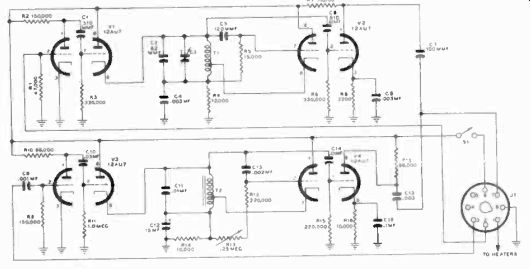
Figure 18. Schematic circuit of Crosshatch Generator
10-25 Other Instruments. At present, few instruments are available which meet all the requirements of television servicing.
As an example, no one oscillograph has good low frequency, high gain, and 4- Mhz bandwidth. The high frequency response of some high-gain, low-frequency oscillographs, such as the Du Mont Type 208-B, may be extended by using a Tel-Instrument video amplifier known as a Teledapter. Other accessory devices which increase the range of most television test equipment should be investigated as they appear on the market. Several new instruments, such as the portable Raytheon sync generator, have made their appearance; and undoubtedly, more useful aids for television servicing will become available in the future.
-------------