All types of radio broadcasting are dependent upon the wireless transmission of speech, music, pictures or some other signal, through the air. The final link between the individual transmitting station and the multitude of widely displaced receivers is the antenna. The antenna may exist in many forms, but in any form its purpose is to radiate or receive signal-bearing radio frequency energy.
5-1 The Transmitting Antenna. The transmitting antenna is designed to meet the particular requirements of the television broadcast station. Such stations operate on frequencies which are characteristically different from those of AM stations, and, moreover, they must transmit with good uniformity a wide band of frequencies. Care must also be taken to achieve radiation that will be substantially equal in all directions along the earth's surface.
In the early days of television, separate antennas were employed to radiate the picture signal and its accompanying sound signal. Today, the transmitting antenna is designed and constructed so that its effective bandwidth is adequate for the faithful transmission of both the picture and sound signals, which together occupy a band of frequencies six megacycles wide.
5-2 The Receiving Antenna. The finest television receiver may be said to be only as good as the antenna to which it is connected.
The considerations involved in the design of a television receiving antenna are different from those of the broadcast receiving antenna, which is usually short compared with the received wavelength. Because of the higher frequencies employed for television broadcasting, a receiving antenna one-half or more wavelengths long is generally used and constitutes in itself a tuned circuit.
Another unusual characteristic of the television receiving antenna is the wide band of frequencies over which it must perform. An efficient antenna must be capable of providing adequate reception free from ghosts and other interference on all the television channels serving the area. In order to be able to select the proper antenna for a given installation, a thorough knowledge of the basic antenna elements which are combined to achieve the desired television reception, is of paramount importance.
5-3 Behavior of Radio Waves. The answers to many of the questions as to why one type of antenna is better than another are to be found in the nature of radio waves and the ways in which they travel. The behavior of waves of different frequencies gives the clue to important points in antenna design. An elementary knowledge of wave propagation will lead to a reasonable explanation of what to expect.
5-4 Wavelength vs Frequency. Radio waves, unlike the transmitting apparatus which produces them and the receiving apparatus which converts them to useful information, cannot be seen or touched. We know that they travel with the speed of light (300,000,000 meters, or 186,000 miles, per second in vacuum), that they are electromagnetic, and that they can be refracted and reflected.
The relation between wavelength and frequency is expressed by the equation:
X = 300,000,000
where X is the wavelength in meters (39.38 inches), and f is the frequency in cycles per second.
5-5 Classification of Frequency Bands. Practical limitations on the size of a radio antenna result in very little power being radiated at frequencies less than 15,000 cycles per second, so that only frequencies greater than that are used in radio communication. The frequencies used in radio communication are classified as follows:
Frequency Range
Nature of Range Abbreviation
Below 30 KHZ
Very low frequencies VLF
30-300 KHZ
Low frequencies LF
300-3000 KHZ
Medium frequencies
MF 3000-30,000 KHZ
High frequencies HF 30-300 mhz
Very high frequencies VHF 300-3000 mhz
Ultra high frequencies UHF 3000-30,000 mhz
Super high frequencies SHF
5-6 Television Frequency Allocation. The channels used for television are between 44 and 88 megacycles, and between 174 and 216 megacycles and are in the VHF band.
Channel No. Megacycles Channel No. Megacycles
1 44-50 7 174-180
2 54-60 8 180-186 3 60-66 9 186-192 4 66-72 10 192-198 5 76-82 11 198-204 6 82-88 12 204-210
13 210-216
In addition to the above channels, which have been assigned to commercial television broadcasting, a group of frequencies in the UHF band, 2000 and 6800-7050 mhz, have been assigned to mobile relay television broadcasts and STL's (studio to transmitter links).
5-7 Electric and Magnetic Fields. The radio wave energy which is emitted from a transmitting antenna is divided equally between an electric field and a magnetic field. This radio wave energy may be represented by a latticework of horizontal and vertical lines as shown in Figure 1. If the horizontal lines represent the electric field, the vertical lines are the magnetic field.
The plane containing the latticework represents the wave front, and the direction of the wave's travel is always perpendicular to the wave front.
5-8 Intensity of the Wave. The intensity of the wave is usually expressed in microvolts or millivolts per meter, which is a measure of the dielectric stress produced by the electric field, or the voltage induced in a conductor 1 meter long held at right angles to the magnetic field and the wave front.
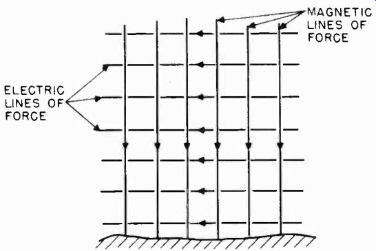
Figure 1. Representation of the magnetic and electric fields of horizontally
polarized wave.
5-9 Wave Polarization. The polarization of the radio wave is determined by the direction of the electric lines of force. A radio wave with its electric field horizontal is said to be horizontally polarized, and one with its electric field vertical is said to be vertically polarized. A horizontal antenna generates a horizontally polarized wave, and a vertical antenna generates a vertically polarized wave.
A horizontally polarized wave traveling in contact with conducting ground falls off very rapidly as it progresses from the antenna, because the electric field is in effect short-circuited by the ground. The electric field of a vertically polarized wave, being perpendicular to the earth's surface, does not fall off nearly so rapidly. The ground acts like a conductor at frequencies up to about five megacycles, but more like a dielectric at higher frequencies.
5-10 Receiving Antenna Orientation. The energy taken from the radio wave by the receiving antenna is greatest when the antenna orientation is the same as the direction of the transmission path of the arriving wave, and has the same polarization. Because of the directive feature of television receiving antennas, it is highly advantageous to point the antenna as accurately as possible in the direction of the transmitter. Note that pointing a receiving antenna involves pointing the broad side of the antenna, and not the ends, toward the transmitter.
5-11 Wave Reflection. Radio waves are reflected by a process very similar to that by which light waves are reflected by a mirror. The efficiency with which the reflection of radio waves occurs depends upon the frequency of the wave energy and the nature of the reflecting surface or object. Size, smoothness and electrical conductivity are factors determining the reflective efficiency of objects in the path of radio waves.
The surface of the earth is a good reflector, particularly of those waves which are incident to it at small angles from the vertical. Layers of the ionosphere which exist from 30 to 200 miles above the earth's surface, also reflect radio waves in the frequency bands below 40 mhz.
5-12 Wave Refraction and Diffraction. The gaseous nature of the earth's atmosphere results in a changing dielectric constant.
This variation in the dielectric density of the atmosphere causes radio waves passing through the air to be refracted downward toward the earth. Likewise, radio waves grazing the edge of the earth's surface in passing, will deviate from their straight path, resulting in a bending or diffractive effect.
Refraction and diffraction are of interest because their effect enables the television frequency wave to follow the earth's curvature, giving propagation conditions approaching that for a plane earth for some distance beyond the horizon.
5-13 Modes of Propagation. The waves radiated from an antenna may travel either along the surface of the ground, or in the atmosphere above the earth's surface. The ground wave is useful only for short distances at the higher frequencies, but the useful range increases as the frequencies are lowered. Long distance radio transmission takes place by means of the sky wave, radio energy which travels from the earth to the upper atmosphere and is there reflected back to the earth's surface some distance beyond the transmitter. Both modes of wave propagation are shown in Figure 2.
5-14 Low Frequency and Medium Frequency Propagation. Waves of low frequencies between 15 and 300 KHZ and medium frequencies between 300 and 3000 KHZ are transmitted by ground wave with less energy loss than are high frequencies. At these low frequencies, conductivity of the underlying terrain is more important than the dielectric constant.
Because of the long wave lengths involved, antennas for transmission of these frequencies are physically and electrically close to ground. The radio waves are long enough to be propagated around small obstacles and gentle curves, such as the earth's surface, with little obstruction. At low frequencies, radio transmission over long distances takes place by a combination of the ground wave and sky wave. Propagation of waves at these low frequencies has the characteristic of being guided between the concentric conducting surfaces of the ionosphere and the earth. The ground wave and sky wave are not as easily distinguishable at low frequencies as at medium frequencies.
The polarization of radio waves at these frequencies is vertical.
5-15 High Frequency Propagation. The range of the ground wave decreases with increase of frequency in the high frequency band between 3 and 30 mhz. In this band, the dielectric constant plays a greater role in the decrease of the ground wave field with distance.
IONOSPHERE
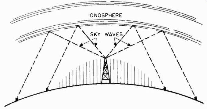
Figure 2. The two principal modes of wave propagation.
At night, there may be sky wave propagation for frequencies as low as 3 mhz, and frequencies above 8 and 10 mhz will penetrate the ionosphere at all angles. However, in the daytime, frequencies of about 3 mhz are strictly confined to ground wave propagation. Frequencies between 5 and 10 megacycles will produce sky waves in the daytime.
In general, the higher frequencies in this band are favorable for long distance day propagation, dependent on the conditions of the ionosphere.
5-16 Propagation at Frequencies Above 30 MHZ. At frequencies above 30 mhz the decrease of the ground wave field intensity is much more rapid than for lower frequencies. For antennas close to the ground, the field intensity varies roughly inversely as the square of the distance. However, this rapid ground wave attenuation can be overcome in part by the elevation of both the transmitting and receiving antennas a number of wavelengths above ground. This is practical at these frequencies because the physical equivalent of the electrical wavelength is comparatively small. All frequencies in this band are heavily absorbed by the ionosphere, and sky wave transmission is sporadic, if it exists at all.
5-17 Characteristics of Very High Frequencies. Very high frequency waves used for television purposes are not regularly returned to the earth at great distances. Normal transmission at television frequencies is due chiefly to the direct and ground reflected wave components of the surface wave. Transmission over long distances far beyond the horizon is occasionally possible as a result of unusual atmospheric or ionospheric conditions. However, the reliable transmission range of the television transmitter is generally taken to be at the horizon.
5-18 Line of Sight Propagation. At television frequencies the surface wave is absorbed very rapidly as the distance from the transmitter is increased. If the transmitting location is visible from the receiver, the very-high-frequency signals can usually be transmitted reliably both day and night, with very little fading or other irregularities from atmospheric causes.
The optical line of sight distance may be calculated by the following equation:
D = 1.23 (1T +ITITR)
... where D is line of sight distance in miles.
HT is height of transmitting antenna in feet.
HR is height of receiving antenna in feet.
5-19 Radio Horizon. For very high frequencies an extension of the transmitting range is achieved by refraction. This modification to line of sight propagation is known as the quasi-optical, or radio horizon, distance.
The radio horizon is expressed by the equation:
D = 1.42 WW1, +)
.... where D is radio horizon distance in miles.
HT is height of transmitting antenna in feet.
HR is height of receiving antenna in feet.
This equation includes the effect of a gradual change in the dielectric constant of the earth's atmosphere which, for standard conditions, causes a refracting effect equivalent to increasing the earth's radius by one-third. Figure 3 shows the relation between the transmitting distances and the height of the antennas.
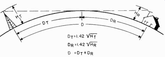
Figure 3. Radio horizon distance between transmitter and receiver.
5-20 Effect of Height at the Transmitting Antenna. If should be noted that whereas the distance range of the ground wave at low frequencies can be increased effectively by increasing the radiated power, the distance range at television frequencies can be increased effectively only by increasing the height of the transmitting and receiving antennas. The need for height to increase the range of transmission is the primary factor in the installation of transmitting antennas, resulting in their placement on the tallest buildings or topographical points in the community.
5-21 Range of a Metropolitan Television Station. A Metropolitan Station is limited by the Federal Communications Commission to a maximum of 50 kilowatts effective peak power with an antenna having a height of 500 feet above the average surrounding terrain.
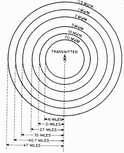
Figure 4. Ground-wave signal range of television station.
The effective radiated power at the antenna is the product of the input power at the antenna and the antenna power gain factor.
If the center of the antenna is exactly 500 feet above the average terrain, the broadcaster is permitted to operate so that this product is exactly 50 kilowatts. If the antenna height is greater than 500 feet, the product of the power input and antenna gain must be reduced in proportion to the increased height of the antenna. However, the effective radiated power is still 50 kilowatts because the propagation efficiency of the antenna is increased in proportion to its added height above average terrain.
Therefore, the signal intensity for all metropolitan stations at an appreciable distance from the transmitter, is the same. Figure 4 shows the signal intensity which can be expected as the receiving distance is varied, assuming that the transmitting antenna is 30 feet high and is horizontally polarized.
5-22 Effect of Height at the Receiving Antenna. Increasing the receiving antenna elevation is often the simplest way to improve circuit performance. Raising the receiving antenna 30 feet results in a signal gain of as much as 10 to 1.
ANTENNA ELEVATION IN FEET

Figure 5. Gain in field intensity of a horizontally polarized dipole antenna
when it is raised from low elevation.
This gain represents an increased RF signal-to-noise ratio as long as the receiver noise is the controlling factor. This might be the case where the receiver is located on the fringe of the service area and insufficient signal is available at lower elevations for adequate service. When external noise is controlling, the gain in signal intensity obtained by raising the receiving antenna may be ineffective, if in improving the RF signal-to-noise ratio the received noise is increased along with the signal. The graph in Figure 5 shows the gain in the field intensity of a horizontally polarized dipole antenna when it is raised from a low elevation. This graph applied to both the transmitting and receiving antennas.
5-23 Multipath Reflections. Normally, television signals travel a direct line of sight path from the transmitter to the receiver. When the direct line of sight path to the receiver is blocked by such objects as hills and buildings, it is possible to receive a strong or weakened signal via a reflection.
Reflection is a characteristic of television signals which often results in more than one signal being received from the same transmitter. These signals travel via different paths of varying length and their arrival at the receiver may be staggered in time. Dependent on the attenuation encountered by these multipath signals and the relative intensity of one signal to the others, a visual pattern of interference, known as ghosts will be seen on the receiver picture tube. The reflected signal may be white or black, depending on its polarity, and it may vary in intensity from almost equal to that of the direct signal, to a point where it is just noticeable.
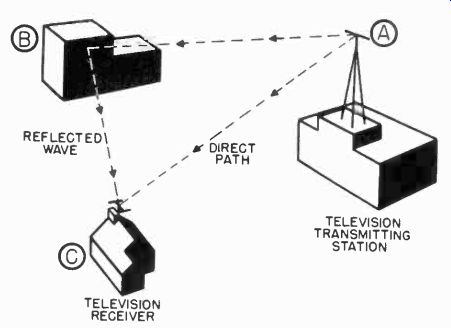
Figure 6. Direct wave and reflected wave striking antenna.
The ghosts of multiple images may occur so that they are not noticeable in themselves, but will instead cause a loss of definition in the picture.. Obviously, in any congested area there may be multiple reflection paths that may set up multiple images.
In some locations, such effects may prevent satisfactory television reception. Figures 6 through 9 illustrate various conditions which cause multipath reflections.
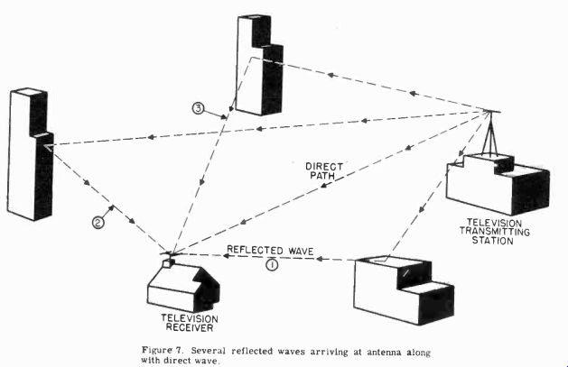
Figure 7.
5-24 The Effect of Terrain Irregularities. Propagation characteristics of television signals over irregular terrain are in marked contrast to the uniform attenuation of the signal with distance when transmitting over level terrain. Here the variation of field intensity with distance depends largely on the profile of the terrain between the transmitting and the receiving antennas. The effects of terrain irregularities upon the television signal are illustrated in Figure 10.
Shadow losses introduced by the earth's curvature and by intervening hills are to be reckoned with. Trees or dense forests near receiving antennas cause more loss of power than at lower frequencies. Fading is often experienced, caused by reflections from airplanes and other moving objects in the path of the radio wave transmission. The limitations placed upon an adequate transmission path between the transmitter and receiver are severe.
5-25 Changes in Polarization. At appreciable distances from the transmitter, the polarization of the television transmission usually varies and is essentially vertical. This is caused by the cancellation of the direct wave by the ground-reflected surface wave components at low angles of transmission (for horizontally polarized waves). See Figure 11. This is also due to the relatively greater attenuation of a horizontally polarized surface wave component as compared with that of a vertically polarized surface wave component.
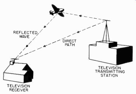
Figure 8. Reflected wave caused by moving airplane.
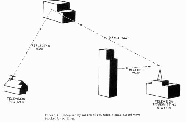
Figure 9.
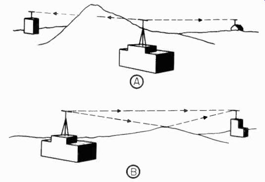
Figure 10. (A) Television signal weakened by intervening hill. (B) Multipath
reflection caused by a “bounce" signal.
5-26 Factors Affecting Television Transmission. Obviously, there are a considerable number of advantages in the use of very high frequencies for television. Some of these are:
a. Frequencies in the VHF band are usually free from atmospheric static noise except during local electric storms.
b. There are no seasonal variations in the characteristics of the transmission path. Signals are therefore solid, except when affected by changes in meteorological conditions.
c. Quarter wavelength and half wavelength antennas in the VHF band are physically small, and therefore very efficient antenna systems are possible.
d. The performance of the VHF receiving circuits may be improved substantially, except under certain conditions, by raising receiving antennas to moderate elevations above the ground.
e. Directional receiving antennas for improving transmission in the desired direction are of relatively small dimensions, and directivity gains equivalent to raising the transmitting power by four times or more are not hard to attain.
5-27 Function of Transmission Lines. The term "transmission line" is applied to electrical conductors which are employed to convey electrical energy from one point to another. The widest application of transmission lines is their use in conjunction with antenna systems.

Figure 11. Cancellation of direct wave by ground-reflected wave.
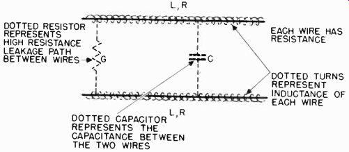
Figure 12. Distribution of resistance, capacitance, and inductance along
section of two-wire transmission line.
It is almost impossible to find a modern high frequency antenna system which is not coupled or matched to the transmitter or receiver by means of a transmission line. The more complex antenna systems employ lines as a means of establishing proper phase relations between the various elements of the antenna array. Since an antenna system without an associated transmission line network is a rarity, a working knowledge of transmission line fundamentals is essential to a complete understanding of television antennas.
5-28 Properties of Transmission Lines. Transmission lines are not perfect conductors; that is, in the transfer of radio frequency energy from one point to another via a transmission line, some loss in energy occurs. This loss cannot be accounted for entirely by the resistance of the conductors.
The line has properties other than pure resistance which may cause additional losses. These properties of the line are series inductance, shunt capacitance, and resistance leakage across the line in addition to the series resistance. These properties are not unlike the common inductors, capacitors and resistors used as circuit components. In the RF transmission line, however, these quantities are uniformly distributed throughout the length of the line and cannot be separated from each other.
Figure 12 shows how resistance, capacitance, and inductance are distributed along a short section of a two-wire transmission line.
In view of these properties of resistance, inductance and capacitance, it may be concluded that all transmission lines present an impedance to the flow of RF energy.
5-29 The Non-Resonant Line. It has been pointed out that transmission lines offer an impedance to the flow of RF. All transmission lines have a property which is called the "characteristic" or "surge" impedance of the line. If a generator with a characteristic impedance equal to that of a line is connected to an infinite length of that line, a perfect transfer of energy from the generator to the line occurs. The signal travels down the line, with its energy gradually being dissipated in the line losses, until none is left.
A resistive load equal to the characteristic impedance may be employed instead, to terminate a finite length of the line.
In this case, the energy (less the line losses) is dissipated in the resistive load. A transmission line which is terminated in this manner is called a non-resonant, flat, or matched line.
Such lines are excellent for feeding an antenna at some distance from the transmitter or in connecting an antenna to a receiver.
They have the disadvantage that their use is normally restricted by the antenna to one narrow band of frequencies.
5-30 The Resonant Line. At frequencies above about 40 mhz, sections of transmission line approach the wavelength of the energy they convey. Because of their comparatively small dimensions and their extreme flexibility, tuned or resonant trans mission lines find widespread use.
A resonant transmission line assumes many of the characteristics of a resonant circuit which is composed of lumped inductance and capacitance. When sections of line are used as tuned circuits, they also produce the effect of high-impedance (parallel resonant circuits) and low-impedance (series resonant circuits) common to conventional tuned circuits. Tuned lines may also be used as transformers. The transformer is widely used as a high efficiency impedance matching circuit.
5-31 The Infinite Line. Although an actually infinite line is impossible to attain, its usefulness is due to the fact that a knowledge of its behavior is of great assistance in determining the operating conditions of an actual line. Furthermore, any length of line can be made to appear like an infinite line if it is terminated in its characteristic impedance.
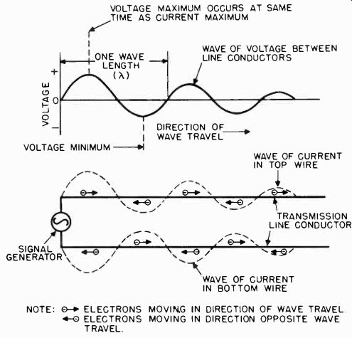
Figure 13. Voltage and current distribution along infinite line.
5-32 Wave Motion On a Line. Figure 13 shows the RF voltage and current waves that exist on an infinite line. The voltage and current maximums are at the same points on the line, but because of line losses they keep diminishing in amplitude as the wave travels down the line. This figure illustrates what would happen if the voltage and current could be stopped for an instant in time, as if a movie film were stopped at a single picture. An instant later in time, all waves would have moved to the right slightly as they continue to travel down the line.
Waves exist because it takes a certain amount of time for electrons to transfer energy down a wire by means of their motion. For example, if a pebble is dropped in the center of a small pool of water, the disturbance does not reach the edge of the pool immediately. Rather, a wave of water starts out from the place where the pebble hits and proceeds toward the edge at a definite speed.
In electrical transmission lines, the time which electrical disturbances or waves take to travel to another point on the line is so small as to be negligible. This is due to the 186,000 miles per second speed of electricity.
5-33 Electrical Length vs Physical Length (Line Velocity of Propagation). The velocity of propagation of radio-frequency energy along a line varies with the types of line. Therefore, the physical or actual length of a line may differ slightly from the computed electrical length because of the capacitance effects between the conductors and between the conductors and ground.
The physical quarter-wavelength for various types of line may be calculated from the formula:
L = 246 V f where L is length in feet.
F is frequency in megacycles.
V is a constant dependent on the velocity of propagation for the particular line in question.
Average values for the constant V for various types of common line are as follows:
Type of Line V
Parallel open wire 0.95
Parallel plastic ribbon line 0.85
Concentric line (Wafer spacers) 0.90-0.96
Concentric line (Solid dielectric) 0.85
Twisted pair 0.56-0.65
To obtain a hall-wave or full-wave section, multiply L by 2 or 4, respectively.
5-34 Reflections On a Line. Consider an RF transmission line in which the load impedance at the output end is infinite or an open circuit. When an RF signal is applied to the input end, the first surge of energy traveling down the line consists of a wave of voltage and current in phase, or with their positive maximum occurring at the same time. However, when the wave of current consisting of electron motion reaches the output end, it falls to zero since there is no additional conductor in which to travel.
When this current wave collapses, the magnetic field set up about the conductors also collapses. The collapsing magnetic field induces a voltage in the conductors near the output end of the line. This induced voltage acts, in a way, like a reverse signal and sets up new current and voltage waves which travel back on the line toward the input end.
The analogy illustrated in Figure 14 shows the standing waves produced on a rope by wave motion and reflection. The electrical-wave and the rope-wave actions are both forms of wave reflection.
5-35 Standing Waves. If a line is terminated with an impedance mismatch at the output or receiving end, it produces reflections.
This means that as the initial energy from the input or antenna end of the line continually surges back and forth on the line, the reflected wave combines with the original wave and thus creates a standing wave.
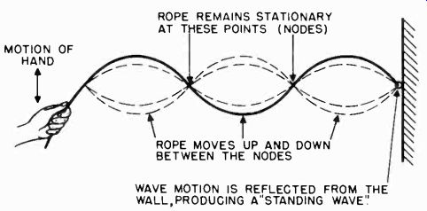
Figure 14. Standing waves produced in a rope.
When the line is unshielded, these stationary waves radiate into space, creating serious interference in other receivers nearby. In addition, the reflections increase the line losses, reducing the line efficiency; and where the line is over 50 feet long, ghost images may be seen on the television receiver screen. If the line is less than 50 feet long, the ghost effect may be negligible.
It is important to note that mismatches as high as 2 to 1 are considered acceptable, and will result in an efficiency loss of only ten percent. Under these conditions, a 150 ohm line could be used to match load impedances ranging from 75 to 300 ohms. However, it is always desirable to attempt as close a match as possible.
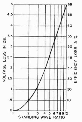
Figure 15. Curve showing the voltage loss in db and the efficiency loss in
percent for various standing wave ratios.
5-36 Determination of the Standing Wave Ratio. The voltage standing wave ratio (VSWR) is the yardstick for measuring the impedance mismatch on a line. This is simply the ratio of the minimum voltage to the maximum voltage on a line. These measurements are made with an RF vacuum tube voltmeter at intermediate points along a length of the line at least one-half wavelength long. On a flat or matched line, the voltages measured at all points on the line would all be within ten percent of one another for a VSWR of 1.1 to 1. This is the procedure used in the field for determining the VSWR for high power transmission lines. The curve of Figure 15 shows the voltage loss in db and the efficiency loss in percent for various standing wave ratios.
In lines used for receiving, such a measurement would require special laboratory facilities due to the low level of the RF signal and the modulation of the RF signal. The determination of the VSWR for receiving lines must be practical, and therefore it is qualitative. The picture is the final measure of whether or not the line is properly matched. The effectiveness of all adjustments made to the antenna system is measured in terms of picture improvement. This is the purpose of the test pattern, which has been designed so as to lend itself to a critical qualitative analysis.
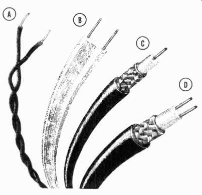
Figure 16. Four types of transmission lines. (A) Twisted pair. (B) Two-wire
line. (C) Coaxial line. (D) Shielded pair.
5-37 Circuit Effects of Resonant Transmission Lines. A resonant line can be defined as a line which possesses standing waves of current and voltage. The line is of finite length and is not terminated in its characteristic impedance. The resonant line is resonant at only one particular frequency.
In practical television receiving applications, the line may be considered resonant over a band of frequencies when designed to the geometric center of the frequency band desired. In such a case it is acting as either a high-resistive or low-resistive impedance. In order to act in this manner, the line is either open-circuited or short-circuited at the output end and is cut to some multiple of a quarter-wavelength. If the length is not a multiple of a quarter-wavelength, the line acts as a capacitor or inductor.
5-38 Balanced Transmission Lines. The twisted pair and two wire parallel conductor are types of balanced transmission lines.
A line is said to be balanced to ground when the capacity between each conductor and ground is uniform along its entire length. If radiation or noise pickup is to be avoided in an unshielded balanced line, the current flow in each conductor must be equal and opposite in direction.
This condition can be achieved only if the line is clear of conducting surfaces. At the higher frequencies, materials such as wood and brick will, when sufficiently damp, begin to act like conductors, adding to the difficulties encountered. In any case, these lines should not be permitted to swing free, but should be fastened securely, at regular intervals, with high quality insulators, if stable characteristics are to be obtained.
5-39 Twisted Pair. Twisted pair consists of two insulated wires twisted together to form a flexible line without the use of spacers (Figure 16A). It is the easiest line to construct. It is generally used as an untuned line in low frequency applications. It is not used at higher frequencies because of the high dielectric losses occurring in the insulation, 4 db for each one hundred feet at 50 megacycles being typical. As in all lines, this loss increases with frequency.
Twisted pair may be used to match impedances ranging from 40 to 150 ohms. The disadvantages common to balanced transmission lines generally apply to twisted pair.
5-40 Two Wire Parallel Line. One of the most widely used types of line is the two-wire parallel line. In its simplest form it consists of two parallel conductors, maintained at a fixed distance apart by means of insulating spacers placed at suitable intervals. This line is used widely because of its economy and efficiency.
A two wire parallel line, enclosed in a plastic ribbon of Polythene is a recent version of this type of line (Figure 16B). Polythene, a synthetic plastic with a yellow waxey appearance, has excellent dielectric characteristics for this type of application.
In addition to its flexibility, the line has low loss, about 1.2 db per 100 feet at 50 megacycles. Common impedance values for commercially available plastic ribbon line range from 75 to 300 ohms.
5-41 The Shielded Pair. This line consists of two separate parallel conductors which are insulated from each other by a low loss dielectric, such as Polythene (Figure 16D). The conductors are contained within a tubing made of copper braid, which acts as a shield. The entire assembly is covered with a rubber or plastic composition for weather proofing.
The shielded pair has two outstanding advantages. The individual conductors are shielded against pickup from stray radiation or noise fields, and the line is balanced to ground at all points owing to the enclosing shield. It may be run close to conducting objects without fear of its becoming unbalanced. This line may be used in strong interference areas. The losses encountered in this line are not much better than for ordinary twisted pair, and its use should be restricted to strong signal locations. Typical impedance values range from 50to 100 ohms.
5-42 Coaxial Line. Coaxial line has advantages which make it very practical for efficient operation at very high and ultrahigh frequencies. It consists of a wire inside of, and coaxial with, a concentric outer conductor (Figure 16C). The outer conductor may be flexible or solid, depending upon the inner conductor support. When the inner conductor is supported by a solid dielectric such as Polythene or Copalene, the outer conductor is normally flexible copper braid. In special cases where the line is used to connect high power transmitters to their antennas, the outer conductor is hard drawn copper and the inner conductor is supported at regular intervals by high grade insulating wafers or beads.
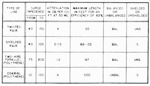
Figure 17. Characteristics of various types of transmission lines.
The signal energy is confined to the inside of this line and there is no loss of signal due to radiation. The outer shield reduces noise and stray radiation pickup. The line is unbalanced and must be properly connected to the receiver with the shield to ground in order to be effective. The line loss is dependent upon the insulating material used and may be as low as 0.4 db per hundred feet. It is available in impedances ranging from 10 to 150 ohms.
The important characteristics of the various types of transmission lines are compared in the chart of Figure 17.
5-43 Characteristic Impedance. The characteristic impedance of a transmission line is directly proportional to its L/C ratio.
An increase in the separation between the conductors of a two wire line or between the inner conductor and concentric outer conductor in a coaxial line, increases the inductance and reduces the capacity. Thus the effect of increasing the spacing is to increase the characteristic impedance, since the ratio L/C is increased. Reducing the diameter of the conductors in a two wire line, or reducing the diameter of the inner conductor with respect to the diameter of the concentric conductor in a coaxial line, also increases the characteristic impedance. This change is brought about by a reduction of the inter-element capacity of the line.
The characteristic impedance of both types of lines may be reduced by increasing the dielectric constant of the insulating material between the conductors. This change is due to the increased capacity of the line. Therefore, it is apparent that conductor size, spacing and dielectric material are the factors determining the characteristic impedance of the line.
5-44 Characteristic Impedance of a Two Wire Parallel Line.
For a two wire parallel line the characteristic impedance is given by the following formula:
Z = 276 log b
}K a
where K is the dielectric constant (1 for air). b is the spacing between conductor centers.
a is the radius of the conductor.
For a line using Polythene dielectric the value of 1/1%K is equal to 0.675. Useful values of impedance for two wire parallel line for television use range from 50 to 300 ohms. The graph of Figure 18 shows the relationship between the characteristic impedance, spacing and conductor size for a two wire parallel line, with air spacing.
5-45 Characteristic Impedance of a Coaxial Line. For a coaxial line the characteristic impedance is given by the following formula:
Z = 138 log b 1K a
where .... K is the dielectric constant (1 for air). b is the inside diameter of the outer concentric conductor.
a is the outside diameter of the inside conductor.
For a line using Polythene dielectric the value of 1/1/Z is equal to 0.675. Useful values of impedance for coaxial trans
mission lines for television range from 50 to 150 ohms. The characteristic impedance of a concentric coaxial line with air spacing is shown for different sizes of inner and outer conductors in the curve of Figure 19.
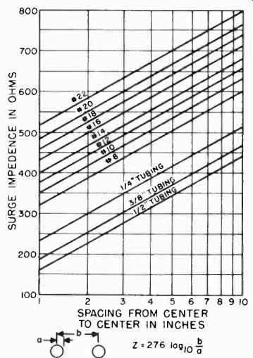
Figure 18. Characteristic impedance of two-conductor parallel transmission
lines.
5-46 Impedance Matching Considerations. In television transmitting systems, it is necessary to keep the impedance match between the antenna and the transmission line leading to the transmitter within plus or minus 10 percent, in spite of the fact that the bandwidth transmitted is less than six megacycles. This is a rather severe limitation. While the receiving antenna must cover a greater bandwidth, receiving antenna system requirements are much simpler, because a good impedance match between the antenna and transmission line is not important. This is true only if there is a good impedance match between the transmission line and receiver input terminals. Mismatching at the antenna is usually tolerable when the antenna impedance is lower than that of the transmission line. A loss of energy transfer and distortion of certain parts of the picture is produced by such a mismatch, but a considerable amount of mismatching can be tolerated before serious degradation of picture quality occurs. The ratio of power lost in an unmatched line to that lost in a matched line is plotted in Figure 20 as a function of standing wave ratio. Note that the power loss does not become appreciable until standing wave ratios above 0.3 are encountered.
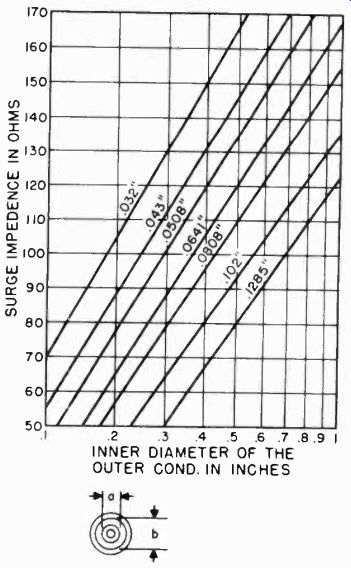
Figure 19. Characteristic impedance of coaxial transmission lines.
Reflections due to mismatching at the receiver input terminals produce "ghosts" which correspond to a delay time equivalent to the time required for the waves to travel back to the antenna and there be returned to the receiver input terminals.
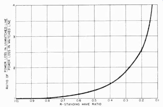
Figure 20. Ratio of power loss versus standing wave ratio.
5-47 Impedance Matching. To obtain maximum efficiency and the elimination of ghosts, the antenna, transmission line, and the receiver should be matched as closely as possible. The wide variation in impedance encountered in television antennas makes it necessary to use special matching devices to avoid serious impedance discontinuities, and to keep the resulting standing wave ratio within reasonable limits.
When an antenna system must operate over a band of frequencies corresponding to several television channels, the resonant matching devices used must be designed for a compromise frequency or the geometric center of the band to be covered. The receiver input impedance, on the other hand, is fixed by the manufacturer over its operating range and is usually 75 to 300 ohms.
Therefore, matching at the receiver merely involves the selection of a transmission line with a corresponding characteristic impedance. The antenna is then matched to the transmission line by a device such as a quarter-wave "Q" section or quarter wave stub matching section. Several examples of matched and mismatched antenna systems are shown in Figure 21. Examples (A) and (B) show two systems with properly matched antennas, transmission lines, and receiver input impedances. Example (C) requires a matching resistive network of standard z watt carbon resistors to match the 75 ohm line to the 300 ohm input to the receiver; it is good in high signal areas where the signal loss across the matching network can be tolerated. Examples (D) and (E) are very poor antenna systems with mismatches of 4:1, and should be avoided. Example (F) shows a 4:1 mismatch at the antenna, but a correct match at the receiver input.
This setup is tolerable where high signals prevail.
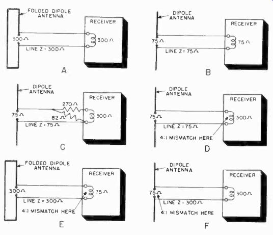
Figure 21. Examples of matched and mismatched antenna systems.
5-48 Geometric Center of Frequency Band. When an antenna system must operate over several television channels, resonant circuit elements must be designed for a compromise frequency.
This frequency is usually the geometric center of the band, and is found by taking the square root of the product of the frequencies at the two extremities of the band to be covered. For coverage of channels 2 to 5 it is equal to 54 x 82, or 66.5 megacycles. For channels 7 to 13 it is equal to )/174-3=216, or 193.8 megacycles.
In practice, the antenna system is often designed to favor the weakest station to be received, instead of cutting, the antenna for the center of the band.
5-49 Quarter-Wave "Q" Matching Section. The "inverting" or impedance transformer characteristic of a quarter-wave section of line can be put to practical and efficient use when it is necessary to match a line of one impedance to an antenna of a different impedance. To do this, the section must have an impedance calculated as follows:
Z = VZA x ZL
where Z is impedance of matching section.
ZA is impedance of antenna.
ZL is impedance of line.
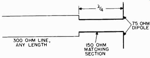
Figure 22. Q matching section.
For example: A 300 ohm line can be matched to a 75 ohm dipole through a quarter-wave section of 150 ohms as shown in Figure 22. The "Q" section should be connected to the antenna directly and should be designed for the desired frequency, taking into account the velocity of propagation for the type of "Q" section used. The "Q" section is necessarily a compromise matching device when required to operate over several television channels.
5-50 Quarter-Wave Stub Matching Section. A popular form of matching transformer consists of a quarter-wave matching stub. If the quarter-wave stub is connected to a voltage loop of the antenna, it is necessary to short the end of the matching section. If the section is left open, it must be connected to a current loop of the antenna. The stub length is calculated from the formula:
L (feet) = 246 f (mc)
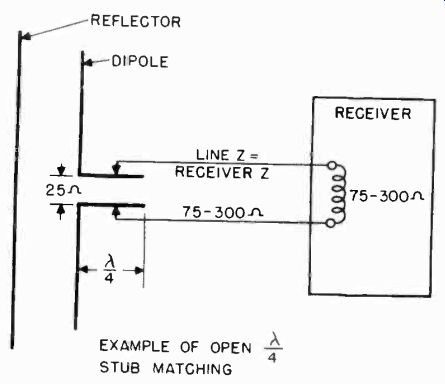
Figure 23. Quarter-wave stub matching section.
The exact length of the matching section and the point of line attachment must be determined experimentally, since it depends upon the impedance of the line as well as the antenna impedance at the point of connection. The impedance of the line is not important since the quarter-wave stub can be used to match practically any impedance. In the example shown in Figure 23 an open-end quarter-wave stub is used to match a 25 ohm antenna to a line of 75 to 300 ohms. The correct match is determined by observing the operation of the television receiver with each adjustment.
ANTENNAS
5-51 Requirements of a Television Antenna. The choice of a suitable antenna system is complicated by the nature of the very high frequency waves used for television broadcasting. Such factors as broad band response, directional characteristics, the elimination of unwanted signals and reflections, and finally, the location of the antenna must all be taken into consideration if satisfactory reception is to be obtained.
A television receiving antenna should be capable of receiving several adjacent channels with equal efficiency. Antenna directivity is required to provide the strongest possible signal at the receiver, as well as to eliminate unwanted signals, wave reflections, and interference.
Antenna location involves the choice of a site where intervening objects, such as hills and buildings, do not block the radio wave path. The television antenna requirements for any location must be considered as an individual problem to be analyzed on its own merits. Constantly differing situations are encountered in the field, and it is important that the technician have a working knowledge of the characteristics of all practical antenna systems used in television.
5-52 Selection of a Television Antenna. There are many types of antennas suitable for receiving television signals, ranging from the simple and selective half-wave dipole to more complex wide-band antenna arrays. In practice, the differences in the various types is chiefly in terms of the frequency rang' of operation, the directivity, and gain.
A wide variety of antennas are commercially available, and it is usually possible to obtain a selective antenna having any desired degree of directivity or shape of field pattern, or to obtain a wide-band antenna system capable of intercepting all channels within either or both of the two television frequency bands. Choice of the proper type of receiving antenna is primarily influenced by the specific requirements and characteristics of each location or site.
If only one station is operating in the region, a selective antenna such as a dipole without, or in combination with reflectors and/or directors usually provides satisfactory reception. If two or more stations are operating on channels in the low frequency television band (44 to 88 mc), a less selective antenna such as a folded dipole, or a wide band array, oriented in the direction which provides equally satisfactory reception of each station is necessary. To receive two or more stations operating on channels in the high frequency band (174 to 261 mc), a proportionately smaller but similar type of antenna is installed.
The satisfactory reception of all television channels (2-13) with a single antenna is sometimes possible, using one of the special types of wide-band multi-channel antennas available.
To favor weak signals or to minimize interference, a highly directive antenna is sometimes employed. Almost any desired shape of field pattern can be obtained with a suitable combination and arrangement of antenna elements. Such special field patterns are required in many cases in order to provide the television receiver with signals of sufficient strength for good visual reproduction.
In metropolitan areas and industrial districts, where television reception is likely to be marred by reflected waves or ghosts and other noise interference, it is sometimes necessary to install individual, highly directive, antennas for the reception of each television station. The effects of interference, due to flashing signs, diathermy machines, elevator motors, and other electrical devices, can be minimized or eliminated with a directional antenna system and a shielded transmission line.
The essential objective in the selection of a television antenna system is to provide adequate, ghost-free, interference-free reception of all the desired television stations operating in the region.
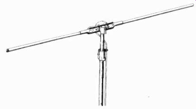
Figure 24. Dipole antenna. (courtesy Ward Products)
5-53 Resonant Antennas. The dimensions off a resonant antenna are dependent upon the frequency of the signal to be received.
An example of a resonant or tuned antenna is the simple dipole, Figure 24, the physical dimensions of which are equal to approximately one hall-wavelength. Other tuned antennas, elaborations of the dipole, are the folded dipole, V-antenna, fanned, and conical antenna.
The shape and dimensions of a tuned antenna affect its bandwidth and, to some extent, its horizontal directivity. The horizontal directivity of a resonant antenna can be increased through the use of one or more reflectors placed behind the antenna. Directors placed ahead of the antenna accomplish the same effect.
Directors and reflectors are parasitic elements and have no electrical connection to the main antenna element. The vertical directivity of an antenna system can be increased by stacking antenna elements a hall-wavelength apart, one above the other.
A combination of stacked antenna elements with directors or reflectors combines the effects of the two systems, giving improved horizontal and vertical directivity.
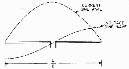
Figure 25. Current and voltage distribution on half-wave dipole.
5-54 Non-Resonant Antennas. The non-resonant antenna is sensitive to an extremely broad band of frequencies, provided certain minimum dimensions are maintained. The principal disadvantage of these antennas is the space required for the erection of an antenna of suitable dimensions. The gain and bandwidth of a non-resonant antenna at any frequency of operation is proportional to its size. There is a minimum size below which it does not provide performance superior to the more compact resonant antennas. Typical types of non-resonant antennas are the long-wire, long-V and the rhombic.
5-55 Dipole Antenna. The dipole is a resonant antenna at the frequency at which its length is equivalent to a half-wavelength.
When excited by an RF signal at its resonant frequency, standing waves of voltage and current are produced along the half wave dipole. The voltage and current distribution is sinusoidal with maximum current and minimum voltage at the center and minimum current and maximum voltage at the ends, as shown in Figure 25.
MAXIMUM RADIATION
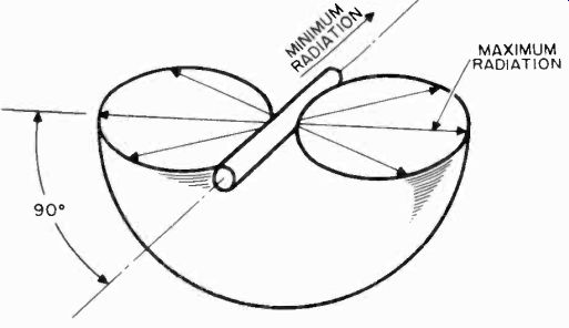
Figure 26. Radiation pattern of half-wave dipole in free space.
The presence of standing waves makes it possible to build up strong electrostatic and electromagnetic fields, and radiation or absorption of RF energy takes place at the resonant wavelength of the antenna. This radiation or absorption field is maximum in any direction perpendicular to the dipole, and is minimum in either direction lengthwise to the antenna, as shown in Figure 26.
5-56 Field Patterns. The directional nature of the radiation pattern is usually indicated graphically by means of either horizontal or vertical field patterns for a fixed antenna in space.
Perfect field patterns are difficult to obtain in practice, because
radio antennas are operated relatively close to the earth and the actual pattern is sometimes distorted and influenced by various ground effects. These effects become less pronounced as the frequency of operation is increased.
Field patterns apply to both transmitting and receiving antennas. In the horizontal plane, they are simple circular charts which resemble the face of a compass, with the antenna located at the center. The circumference of the circular chart is marked off in degrees from zero to 360, representing the bearing from the antenna at the center to the points around the compass. Zero degrees is usually taken at True North or some other convenient reference point.
The computed or measured field strength at each bearing is plotted radially from the center for each angular bearing from the antenna and joined together by a smooth curve. The horizontal field pattern, for receiving antennas, illustrates the relative sensitivity of the antenna at different bearings.
When the field strength of an antenna is plotted so that its amplitude in a given direction is compared to the field strength of a theoretical dipole in the direction of the dipole's maximum sensitivity, the power gain of the given antenna at any bearing may be read from the chart.
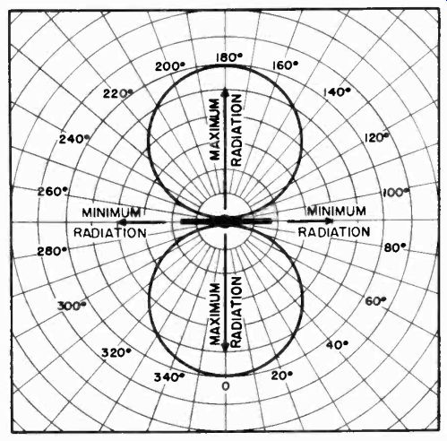
Figure 27. Horizontal field pattern of horizontally polarized half-wave dipole.
The horizontal field pattern of a horizontally polarized dipole is shaped like a figure eight, as shown in Figure 27. The two main lobes of the antenna are not sufficiently narrow to be of great practical value; thus, the dipole antenna has only slight directivity.
A vertical field pattern is similar to the horizontal one, except that it shows the field pattern for vertical angles around the antenna. The vertical field pattern is always given for one horizontal angle of radiation, as shown in Figure 28. This is necessary, since there exists a separate vertical field pattern for each horizontal angle of radiation. For television receiving antennas, the vertical field pattern of most use is that which corresponds to the most sensitive horizontal field strength bearing of the antenna.
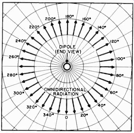
Figure 28. Vertical field pattern of horizontal dipole.
5-57 Directivity. The directivity of an antenna refers to the sharpness or narrowness of its field pattern in a given plane.
An antenna with a sharp pattern in the horizontal plane is said to have good horizontal directivity. An antenna with a sharp pattern in the vertical plane is said to have good vertical directivity. Points on the field pattern at which radiation is zero are called nulls. The curved section between any two nulls is called a lobe. When the directivity of an antenna in a given plane is increased, it is usually accompanied by a reduction in effectiveness of the antenna in another plane.
5-58 Power Gain. This term is used to express the power increase of a given antenna over a standard basic antenna, usually, a half-wave dipole. When referring to a directional antenna, power gain usually means the power gain measured in the optimum direction of the antenna system.
5-59 Length of Dipole Antenna. The physical dimensions of a half-wave antenna element which equals an electrical half-wave is actually shorter than an actual half-wave of the frequency for which the antenna is cut.
In practice, a dipole antenna is usually opened at the center, forming two quarter-wave sections. These sections should be approximately 5% shorter than an actual quarter-wave of the frequency at which the antenna is to operate. The reduced length is necessary to offset end loading effects.
The physical length of the quarter-wave dipole antenna elements, considering end effect, maybe calculated by the following formula:
L = 234 f where L is length in feet.
f is frequency in megacycles.
The lengths of dipole antennas, which are cut for the center frequencies of each television channel, are shown in the chart of Figure 29. The electrical quarter-wavelength corresponding to any frequency may be calculated by the following formula: L = 246 f where L is length in feet.
f is frequency in megacycles.
5-60 Dipole Bandwidth Considerations. When current is fed at the center, dipole and other half-wave antennas have characteristics similar to a series resonant circuit. The Q of an antenna, the ratio of its inductive reactance component to its resistive component, gives some indication of the bandwidth of the antenna.
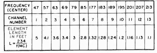
Figure 29. D pole dimension chart.
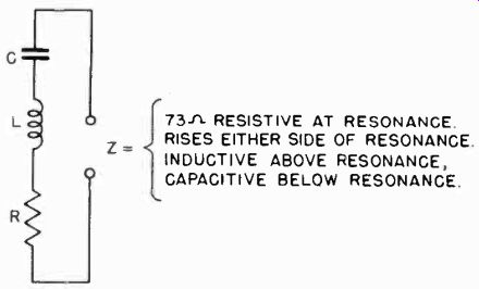
Figure 30. Equivalent circuit of a dipole antenna.
At the resonant frequency of an antenna, its impedance is largely resistive. This condition exists over a band of frequencies whose width increases as the Q of the antenna decreases. It follows that for wide-band television applications, a low value of Q is preferable because of the increased bandwidth obtained.
Physically, the Q of a dipole antenna is a function of the ratio of its length to its diameter. An increase in the diameter of an antenna conductor reduces the inductance, increases the capacity, and thus lowers the Q of the antenna. Large diameter conductors are used for the elements of an antenna when wide band requirements must be met. An increase in bandwidth is accompanied by a decrease in selectivity and a reduction in power gain at the resonant frequency. It is noteworthy that the dipole alone is used effectively for the reception of several adjacent television channels, as well as to form the basis for a wide variety of other types of antennas and arrays.
5-61 Dipole Impedance Characteristics. The equivalent circuit of the dipole antenna is a conventional series resonant circuit (Figure 30). The impedance of the dipole at its resonant frequency is 73 ohms, resistive. At frequencies above and below the resonant frequency, the dipole impedance increases, becoming more and more reactive. By keeping the inductive component of the antenna low and the capacitive component high, the impedance over a broad band of frequencies remains substantially resistive.
A dipole may be made sharply selective by increasing the inductive component and decreasing the capacitive component. In this case, the resistive component is prominent only at resonance and is insignificant in relation to the large reactive components when off resonance.
5-62 Practical Antennas. It has been shown that impedance matching between the receiving antenna and transmission line feeding the receiver is not of primary importance under certain conditions. The loss in efficiency which results, can be tolerated if the transmission line is "bridging" or has a higher characteristic impedance than the antenna. Therefore, impedance matching is not the reason for the many variations of the half-wave dipole antenna which are encountered in practice.
Broad-banding is the major reason for these designs.
All resonant antennas capable of operating over a wide frequency range are characterized by a diameter, or other crosswise dimension, that is relatively large. The use of large diameter or multiple antenna elements does not affect the antenna radiation resistance greatly, but it does reduce the inductance and increase the capacitance, lowering the Q and improving the bandpass characteristics of the antenna system.
Other factors, closely interrelated, which influence television receiving antenna design, are directivity and sensitivity or power gain. Due to the quasi-optical behavior of television frequencies, there is always the possibility of receiving signals originating at the same transmitter over several different paths.
These signals cannot be combined because of the time delay involved in the paths over which the signals travel to the receiving location. Directivity is essential to permit the selection of the desired signal to the exclusion of all of the others. Directivity also has the effect of increasing the sensitivity or power gain of an antenna.
A good picture is one free of distracting background noise.
Added sensitivity provides increased signal strength with respect to noise. The amount of noise introduced into the receiver can be considerably reduced by limiting the horizontal signal admittance angle of the antenna to the minimum required.
To fulfill these various requirements, many types of antennas have been designed. For purposes of discussion, all antennas may be separated into three groups. These groups are: 1 the dipole and variations of it, 2 antenna arrays, and 3 long wire antennas. The balance of this section is devoted to descriptions of the antennas in these groups, starting with the dipole and variations of it.
5-63 Adjustable V Antenna. A variation of the dipole-type receiving antenna consists of a half-wave dipole whose quarter wave elements are moveable in the vertical plane (Figure 31). This dipole is fed ?n the conventional manner, at its center, and pivoted in such a way that each arm can be adjusted to any desired angle above the horizon.
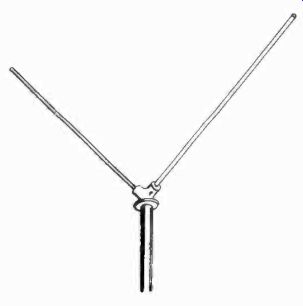
Figure 31. Adjustable V antenna.
This antenna has its greatest application in congested city and industrial areas, where multi-path propagation is severe. Television waves are horizontally polarized at the time of transmission, and normally they retain this polarization during propagation. in urban or metropolitan districts, these waves are often reflected by large buildings and other objects before arriving at the receiving antenna. A wave which travels a reflected path to the antenna, may acquire a vertical component of polarization in addition to the original horizontal component. This combination of vertical and horizontal components effectively "raises" the angle of polarization above the horizontal plane. Therefore, when operating a receiving antenna on a reflected signal, the dipole works best when its angular position corresponds to the oblique angle of the wave polarization received. In practice, the two arms of the dipole are adjusted until the best results are obtained visually on the television receiver picture tube.
5-64 Extended V Antenna. This wide band antenna may be used for television reception in congested city and urban locations, where polarization effects due to multi-path wave transmission are most pronounced. The extended V antenna (Figure 32) provides compensation for this polarization distortion, and has a frequency response sufficiently broad to accept television signals within either of the two frequency bands. The V-shape of the antenna may be utilized to match the antenna properly to a 300 ohm transmission line.
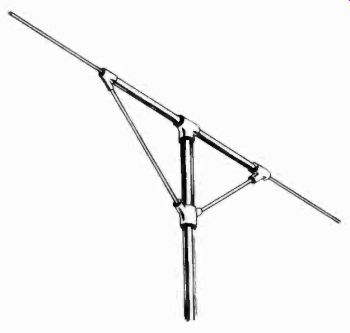
Figure 32. Extended V antenna.
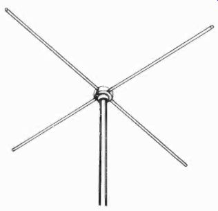
Figure 33. Crossed dipole antenna.
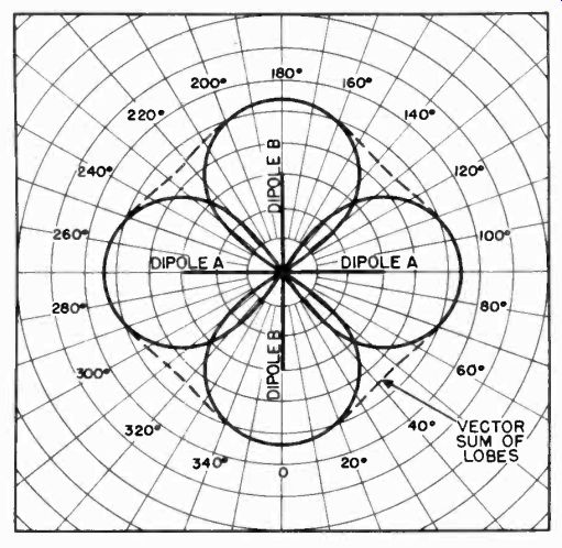
Figure 34. Horizontal field pattern of crossed dipole antenna.
5-65 Crossed Dipole Antenna. In order to obtain omnidirectional characteristics, two horizontal half-wave dipoles may be arranged so that the inherent directivity of each dipole is combined to provide a circular radiation pattern in the horizontal plane. An arrangement of this type is the crossed dipole, or turnstile antenna, which is widely used for non-directional transmission and reception.
The basic antenna consists of two horizontal half-wave dipoles (Figure 33) crossed at right angles in the same plane. When the two dipoles are excited simultaneously with equal currents, differing in phase by 90 degrees, the individual field patterns are combined and the resultant field pattern is essentially circular, or omnidirectional (Figure 34). Because of the frequency sensitive phasing connection between the two sets of dipoles, this antenna is not generally suited to multiple channel television reception. It is also unsuited to many television installations because it cannot discriminate against unwanted signals, and is likely to accept multiple ghost creating signals, waves with polarity distortion, and noise interference. This type of antenna is restricted to transmitting applications, where, in its simple form or one of its many variations, it is used in stacked arrays to provide high-power omnidirectional radiation.
5-66 Folded Dipole. The folded dipole is ideal for television because of its higher input resistance and its broader bandwidth.
With these advantages, the folded dipole retains the radiation characteristics of a simple half-wave dipole. The length of the folded dipole maybe computed from the formula:
L =492/f (mc)
in feet.
Spacing between the two parallel elements is ordinarily less than 3 or 4 percent of the wavelength, and is not critical. The folded dipole is actually two parallel dipoles, carrying equal currents in the same phase. The voltage at the ends of the two dipoles is maintained equal by means of the direct short circuit connections, and the voltage distribution along both dipoles is therefore the same.
The folded dipole is shown in Figure 35. It is constructed with elements of equal diameter. This folded dipole has an input impedance of 300 ohms. When the diameter of the fed element is decreased with respect to the other element, the input resistance increases. When the diameter of the fed element is increased with respect to the other element, the input resistance decreases. This characteristic of the folded dipole makes it possible to construct an antenna of almost any desired impedance.
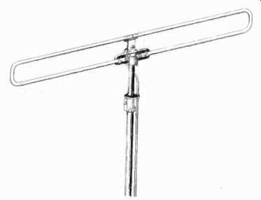
Figure 35. Folded dipole antenna. (courtesy Ward Products)
Folded dipoles are often constructed of 300 ohm ribbon transmission line. This type of dielectric covered antenna should be cut approximately 85% of a half-wavelength of the frequency to be received. This is necessary because the velocity of propagation of the currents in the antenna is due to the dielectric material used. The exact length of an antenna made from 300 ohm ribbon maybe found by multiplying an electrical half-wavelength of the frequency to be received by the factor 0.81. The factor takes into consideration both the antenna end effect and the reduced velocity of propagation due to the dielectric of the 300 ohm plastic ribbon transmission line.
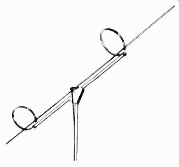
Figure 36. Duo-dipole antenna.
5-67 Duo-Dipole Antenna. The unconventional arrangement of this wide-band receiving antenna (Figure 36) provides coverage of all television channels. The antenna consists of a relatively thin half-wave dipole resonant at 70 megacycles mounted parallel and close to a thicker half-wave dipole, resonant at 128 megacycles. The ends of the short, thick dipole are connected by means of inductive loops to the thin dipole. In addition to feeding the short dipole, these two inductive loops also provide structural support for the long, thin dipole.
For reception in the low-frequency television band, the antenna functions as a wide-band folded dipole resonant at about 70 megacycles, since the long dipole is tuned to this frequency and the short dipole is effectively end-loaded by means of the inductive loops. For reception in the high frequency television band, both dipoles are resonant at the center of the band with all currents in phase, since the long, thin dipole is tuned to a third harmonic of the center frequency, and the short dipole is end-fed by means of the inductive loops. A matching stub permits the use of a standard 300 ohm line with minimum loss of power due to mismatched impedance. In general, the directivity of this receiving antenna remains substantially the same for all television channels. This important characteristic is evident by comparison of the field patterns at 70 megacycles (Figure 37) with the field pattern at 195 megacycles (Figure 38).
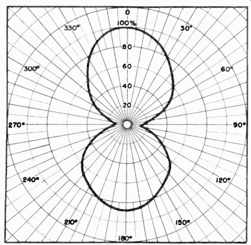
Figure 37. Horizontal field pattern of duo-dipole antenna at 70 Mhz.
5-68 Bat-Wing Antenna. An important modification of the folded dipole, known as the duo band or bat-wing antenna (Figure 39), operates with equal effectiveness on each of the thirteen television channels. This antenna exhibits essentially the same directivity, gain, bandwidth, and other reception characteristics on all channels. This is accomplished with a conventional folded dipole broadly tuned to the center of the low-frequency television band (44 to 88 megacycles), plus a wide band half-wave dipole resonant at 180 megacycles, connected to the terminals of the transmission line in parallel with the large folded dipole. The short modifying elements protrude forward at an angle of 50 degrees, accounting for the "bat-wing" appearance of the antenna.
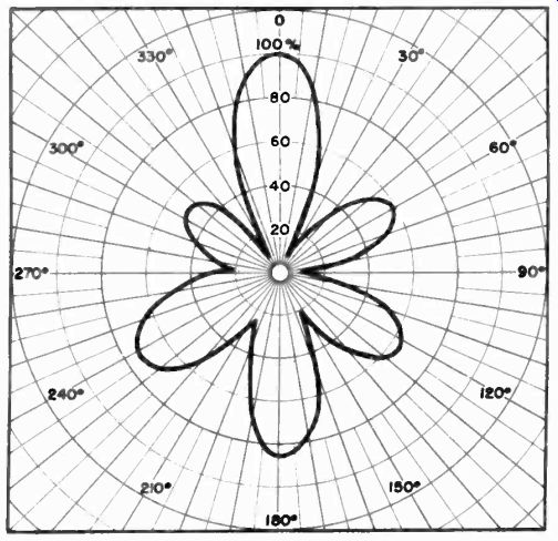
Figure 38. Horizontal field pattern of duo-dipole antenna at 195 Mhz.
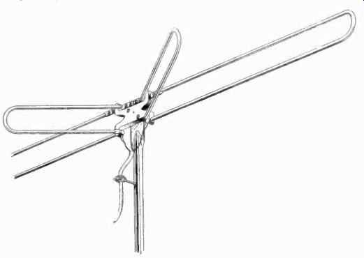
Figure 39. Bat-wing antenna.
For the reception of television channels in the low-frequency band, the antenna functions as an ordinary folded dipole, with a directional field pattern (Figure 40). For reception of television channels in the high-frequency band, however, there is a pronounced directional effect (Figure 41), produced by the resonant modifying elements at the center of the antenna.
5-69 Double-V or Fan Antennas. Another modification of the simple dipole which has a higher input impedance and broader bandwidth is the double-V antenna (Figure 42), the full-wave fan antenna, or any of the several variations based on the number and arrangement of the "fanned" elements used. Maximum reception is perpendicular to the major axis of this type of antenna and, accordingly, the horizontal reception pattern is bidirectional.
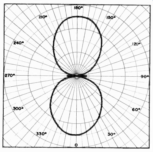
Figure 40. Field pattern of bat-wing antenna at 80 Mhz.
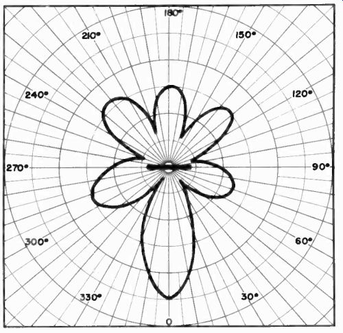
Figure 41. Field pattern of bat-wing antenna at 180 Mhz.
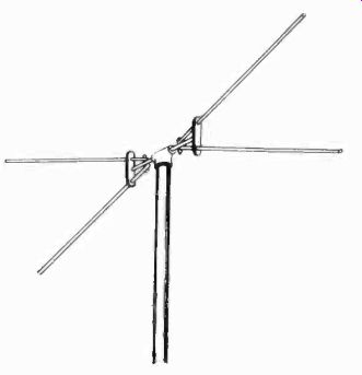
Figure 42. Double-V antenna.
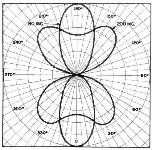
Figure 43. Horizontal field patterns of fan antenna at 80 M and 200 Mhz.
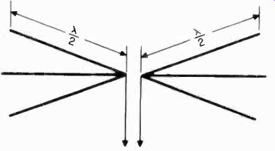
Figure 44. Full-wave fan antenna.
The shape of the simple bi-directional pattern is considerably modified at the higher television frequencies (Figure 43). In the vertical plane, the reception pattern is essentially omnidirectional, regardless of the frequency of operation.
The double-V is the simplest of these antennas. It is usually constructed of quarter-wave dipole elements. Its input impedance is in the order of 100 to 200 ohms. When a double-V antenna is used for broad-banding over all thirteen television channels, it assumes some of the aspects of the full-wave fan antenna (Figure 44). This antenna consists of three full-wave elements on each side of the center feed point. This impedance of a cente RFed full-wave antenna is high, of the order of 600 to 700 ohms.
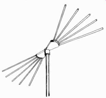
Figure 45. Multi-channel fan antenna.
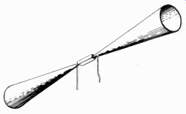
Figure 46. Conical antenna.
Two of these antennas, stacked a half-wavelength apart, would provide a good impedance match for a 300 ohm line.
Another fan antenna (Figure 45) is available which consists of five "fanned" elements, which present a satisfactory impedance match to a 300 ohm line from 44 to 216 megacycles. In this antenna the fans are in the horizontal plane. Its operation over the full 44 to 216 megacycle frequency range is a compromise between á half-wave resonant antenna at the lower frequencies and a full-wave resonant antenna at the higher frequencies.
5-70 Conical Antenna. One of the most effective broad-band antennas for television use is the conical antenna (Figure 46). The low Q needed to obtain broad-band characteristics is obtained in this antenna by the large cross-sectional area. The antenna has a high resistance and a uniform sensitivity over a wide band of frequencies. The length of each cone is critical and should be 0.365 times an electrical wavelength.
The conical antenna may be constructed of sheet metal, equidistantly spaced wires, or of copper screening suitably supported. The physical rigidity of the cone is the major problem encountered with this type of construction. Another advantage of the cone is that it can be constructed to match a selected transmission line of given impedance, by properly choosing the angle of revolution. To match a 300 ohm line, the angle of revolution of the cone should be 15 degrees.
5-71 Rotatable Antenna. Optimum reception of television signals is usually achieved when the receiving antenna is oriented in the direction of the transmitter. When conditions are such ...
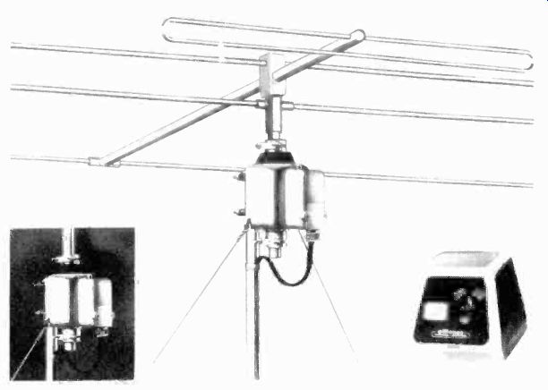
Figure 47. Rotatable antenna. (courtesy Alliance
Mfg.)
... that there is a severe multipath reflection problem, or the desired television signals are originated in widely scattered directions from the receiving location, a number of individually oriented receiving antennas may be required.
In many cases a practical solution to this type of reception problem is a rotatable antenna which can be oriented for any signal, thus providing peak performance at all times. One type of rotatable antenna available is shown in Figure 47. The entire antenna assembly is motor driven and can be rotated in either direction, from a remote control box at the receiver.
Results are observed directly (visually) on the picture tube as the antenna is rotated, providing an indication of accurate orientation. In multipath signal areas, the antenna may not always be pointed at the transmitter, but rather to a reflected signal which provides the best picture.
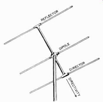
Figure 48. Three-element parasitic array; a reflector and a director with
half-wave dipole.
5-72 Directional Antennas. All practical antennas are directional to some extent. In general, however, the term directional antenna refers to a radiating system which has been designed deliberately to concentrate its radiation in a relatively narrow beam. For transmitting purposes, directional antenna arrays concentrate RF energy in the directions where the signal is desired, and minimize or prevent radiation in other directions.
When used for reception, directional antenna arrays reject or discriminate against unwanted signals arriving from directions other than that in which reception is desired. There are three general classifications into which directional antenna arrays may be grouped. These are:
(a) Parasitic arrays,
(b) Driven or phased arrays,
(c) long wire arrays.
Various combinations of the above types of arrays may be used to provide additional directivity.
5-73 Gain and Directivity. The gain of a directional antenna array is the ratio of the signal strength in the desired direction to the signal strength in the same direction obtainable with a half-wave dipole.
The directivity of an array refers to the shape of its field pattern in either the horizontal or vertical plane. A sharp or extremely narrow field pattern identifies an antenna array with good directivity.
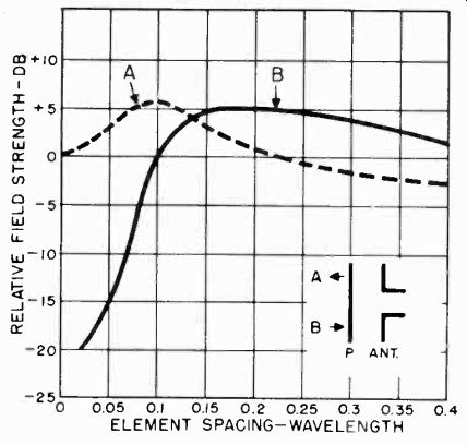
Figure 49. Maximum gain obtainable with single parasitic element. Curve A
shows the gain when parasitic element, P, is director; curve B shows gain
when P is reflector.
Directivity and gain normally go hand in hand, but some systems are capable of added directivity with little or no gain. In this case, the directivity is useful in reducing interference, although no increase in signal strength is obtained.
5-74 Parasitic Arrays. The simplest and most common method of obtaining a unidirectional field pattern for television receiving systems is by means of a parasitic array. A parasitic array consists of a conventional half-wave dipole, and one or more parasitic elements.
There are two types of parasitic elements: reflectors and directors. A reflector is placed behind a dipole, that is, on the side opposite that from which the signal is being received. A director is placed in front of the antenna, in the direction of the received signal. The positions of the reflector and director are shown in Figure 48.
The directivity, as well as the gain, of parasitic arrays is roughly proportional to the number of parasitic elements employed. The size of a parasitic array is proportional to the operating wavelength. At frequencies within the television operating range, the elements which make up a parasitic array are comparatively small. This allows for simple and rugged mechanical construction.
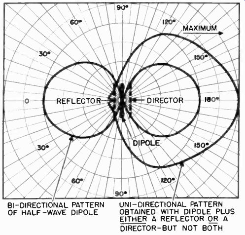
Figure 50. Change in bi-directional field pattern of dipole when either reflector
or director is added to dipole.
5-75 Two Element Arrays. The gain in field strength with a reflector or director as compared to a dipole alone depends upon the spacing between the antenna elements and the length of the parasitic element. The maximum gain obtainable with a single parasitic element, as a function of the spacing, is shown in Figure 49. The curve shows the greatest gain to be expected when the parasitic element is the correct length for optimum performance, either as a director or a reflector. The shift from director to reflector, with the corresponding shift in direction, is shown in Figure 50. In other words, the parasitic element may be either a reflector or a director at any spacing.
5-76 Reflectors. A reflector is a metal conducting rod placed parallel to and behind a half-wave dipole in a position opposite the field of maximum intensity, Figure 51. It is slightly longer than the dipole element, and is not connected to the dipole antenna or its associated transmission line. The curves in Figure 52 show the length in feet of a dipole and a reflector for frequencies from 45 to 95 mhz. Since curve A (length of reflector) is above curve B (length of dipole), for any given frequency the reflector is always slightly longer than the antenna.

Figure 51. Dipole and reflector.
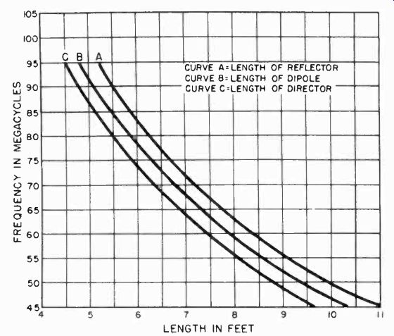
Figure 52. Curves showing length in feet of dipole, reflector, or director
for frequencies between 45 and 95 Mhz.
Analyzing the operation of the reflector for transmitting antennas will help the reader understand its operation when receiving.
When the dipole is energized, the resultant field induces a voltage in the reflector element. This induced voltage, in turn, produces a field at the reflector which is opposite in polarity and almost equal in magnitude to the original induction field. Thus, there are actually two separate radiation fields to be considered; that caused by the current in the dipole radiator, and that caused by the induced current in the reflector element. Very little energy travels beyond the reflector in the direction away from the dipole, because the fields are of opposite polarity and cancel
one another. The RF energy from the reflector traveling toward the dipole is in phase with the energy radiated from the dipole in that direction, and they combine, mutually strengthening the field pattern in the forward direction (Figure 50). The exact shape of the pattern depends upon the phase relation between the direct and the reflected fields. The phase of the induced current in the reflector is controlled by two factors: (a) the length or tuning of the element, and (b) the spacing between the dipole and reflector.
Almost all two-element parasitic arrays used for television consist of a dipole and reflector, rather than a dipole and director.
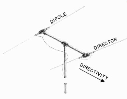
Figure 53. Dipole and director. (courtesy Oak Ridge).
5-77 Directors. A director is a metal conducting rod placed parallel to and in front of a half-wave dipole in the direction of the desired field of maximum intensity (Figure 53). It is slightly shorter than the dipole element, usually about 4%. The length in feet of a director for frequencies from 45 to 95 mhz is shown as curve C in Figure 52. Since curve C is below curve B, the director is always slightly shorter in length than the dipole.
The director is not connected to the dipole antenna or its associated transmission line. When the dipole radiator is energized, the resultant field induces a voltage in the director so that there is a reinforcement of fields in the forward direction, and a cancellation of fields in the opposite direction. This function of the director is very similar to that of the reflector, and essentially the same field pattern is produced (Figure 50), when either a director or reflector is used with a half-wave dipole radiator. The phase of the induced current in the director is controlled by two factors: (a) the length or tuning of the element, and (b) the spacing between the dipole and director. The function of the director is the same when used with either a transmitting or receiving antenna.
5-78 Front-To-Back Ratio. The conditions which give maximum gain forward do not give maximum signal reduction, or attenuation, to the rear. For the sake of good reception, general practice is to adjust an antenna for maximum front-to-back ratio rather than for maximum gain. Reduction of response to signals behind the antenna is brought about by adjusting the length of the parasitic element. Larger front-to-back ratios can be secured with the parasitic element operated as a director rather than as a reflector. With a director, the length must be made slightly shorter than that which gives maximum gain, with spacings of 0.1 wavelength and more. The reflector must be lengthened somewhat to achieve the same end, at spacings up to 0.25 wavelength.
The adjustment of the front-to-back ratio may be performed in practice while visually observing an interference pattern on a television receiver. If the interference pattern is originating in the opposite direction from the desired signal the results of any adjustments are readily apparent.
5-79 Impedance of Parasitic Antennas. The radiation resistance at the center of the dipole, with a reflector, varies as shown in Figure 54, with spacings of the order of 0.1 wavelength. These values are quite low, compared to the 73-ohm radiation resistance of the half-wave antenna alone. At greater spacings the radiation resistance increases. The selectivity of the antenna system becomes higher as the radiation resistance decreases.
This means that optimum performance can be secured over only a narrow band of frequencies as compared with a higher resistance antenna.
5-80 Double Parasitic Arrays. It is possible to use two parasitic elements in conjunction with a half-wave dipole to increase directivity and gain. Generally, one parasitic element is a director and the other is a reflector. The three elements are mounted in the same plane, as shown in Figure 48. The optimum spacings are the same as those for single parasitic elements; that is, director spacing of 0.1 wavelength and reflector spacing of 0.15 wavelength give maximum gain. Tuning for gain and maximum front-to-back ratio is the same as for single parasitic elements. With the director spaced 0.1 to 0.15 wavelength from the dipole, the radiation resistance is of the order of 8 to 10 ohms. Usual practice is to use a director spacing of 0.1 wavelength in combination with a reflector spacing of 0.25 wavelength, with a resultant increase in resistance.
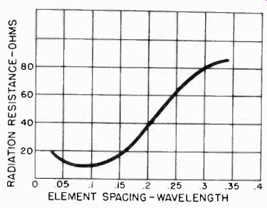
Figure 54. Variation of radiation resistance of dipole and reflector.
Large size tubing of good conductivity must be used for the elements if the gain possibilities of the system are to be fully realized. This system is even more selective than the two element antenna, so that peak performance can be secured over a very small range of frequencies.
This type of antenna is usually found in television receiving installations where a separate antenna is required for each station desired. At times, a single antenna may be used effectively for the reception of two adjacent Channel television stations which are in the same direction from the receiving location.
5-81 Folded-Dipole Parasitic Arrays. The advantage of horizontal directivity and high front-to-back ratio may be obtained by using a folded dipole in an array. The folded dipole has a much higher radiation resistance than the simple half-wave dipole and, therefore, an antenna system with a wider frequency response results with its use. Such an array may consist of one or two parasitic elements (Figure 55).
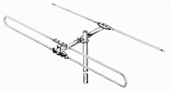
Figure 55. Folded dipole with reflector. (courtesy JFD)
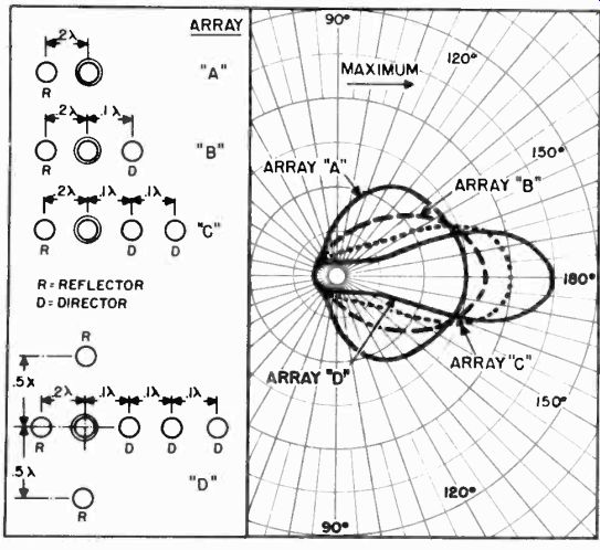
Figure 56. Field patterns of four parasitic arrays.
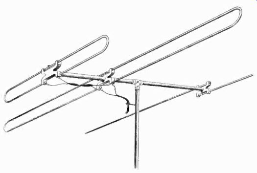
Figure 57. Duo-folded dipole parasitic array.
5-82 Multi-Element Parasitic Arrays. When a high degree of directivity and gain are required, more than two parasitic elements may be used. Such arrays are known as multi-element parasitic arrays (Figure 56), and consist of a number of elements arranged symmetrically with respect to the line and plane of greatest directivity and gain. Any number of directors can be used with a half-wave dipole, and these elements may be combined with one or several reflectors. When four or more elements are used, the arrangement' is often known as a Yagi array. With the addition of each parasitic element, the power gain of an antenna increases approximately 1.4 times. For example, if the power gain of a 4-element array is 5.0, the addition of another director would increase the gain to a value of 6.4, and so forth.
Each director and reflector must be properly tuned and spaced with respect to the dipole element, in order to provide optimum performance. A folded dipole used in the place of a simple half wave dipole will increase the antenna radiation resistance and provide operation over a wider band of frequencies.
Since multi-element parasitic arrays are very selective they have not been widely used for television. An antenna array of this type is suitable for reception of one television channel only.
5-83 Duo-Folded Dipole Parasitic Array. An antenna which consists of two folded dipoles and a parasitic element is shown in Figure 57. This antenna combines a folded dipole tuned to the lower end of the television band with a folded dipole tuned to the upper end of the television band to secure broad band response.
When receiving signals at the low-frequency end of the television band, the small folded dipole acts as a director. The result is a folded dipole antenna with a director and reflector.
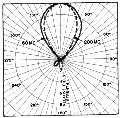
Figure 58. Field patterns of duo-folded dipole at 60 and 200 Mhz.
When receiving at the high frequency end of the band, the small dipole becomes the antenna with the large dipole acting as a reflector. The resultant antenna consists of a folded dipole with two reflectors.
Field patterns for the low and high frequency ends of the television band are shown in Figure 58. These patterns show the antenna to be substantially unidirectional. High front-to-side and front-to-back ratios are maintained over the entire television band.
At 60 megacycles the power gain of this antenna is slightly better than 2, while at 200 megacycles its power gain is approximately 2.5. The antenna matches a 300 ohm transmission.
5-84 Stacked Arrays. The stacked array is used to concentrate the receiving or transmitting antenna sensitivity at low vertical angles. It has been shown how the use of parasitic elements concentrates the antenna sensitivity in one horizontal direction, and reduces the pick-up of unwanted signals and noise from the sides and back of the antenna. A stacked system reduces noise pick-up from top to bottom in the vertical plane and, therefore, further improves the sensitivity of receiving antennas in the desired direction. A stacked horizontal antenna system for television consists essentially of two simple antenna elements and associated components, spaced a half-wavelength apart in the vertical plane.
The antenna elements are excited in phase, that is, signals arriving in the direction of orientation of the antenna system induce in-phase voltages in the antenna which add in the transmission line. Noise or other unwanted signals arriving from top or bottom induce voltages in the antenna system elements which cancel in the transmission line.

Figure 59. Stacked dipole arrays. (A)center fed; (B)transposed feeder.
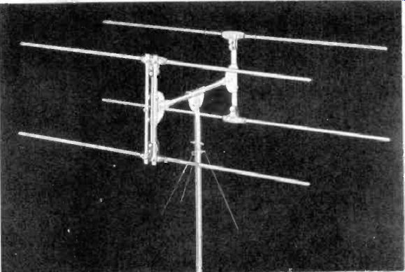
Figure 60. Stacked dipoles and reflectors. (courtesy Cameo)
5-85 Stacked Dipole Arrays. A simple stacked array consists of two half-wave dipoles in parallel in a vertical plane. This antenna system and methods of feeding it are shown in Figure 59. The center feed method shown in B is preferred in as much as the transmission line point of attachment is centered and at the same distance from both dipole elements. Consequently, the signals from both dipoles always appear in phase at the input to the transmission line.
A transposed feeder system can be used, as shown in A. The transposed half-wave feeder system between the dipoles acts as a one-to-one in-phase impedance matching transformer, and the signal from the one dipole element appears in phase at the feed point of the other dipole element. However, the transposed feed is frequency sensitive and must be electrically equivalent to a half-wavelength at the frequency of the desired signal and, therefore, is effective over only a limited range of frequencies.
When two dipoles, or similar antennas, are stacked and fed into a common transmission line, the antenna resistance is halved. Thus, if two simple dipoles are stacked, the antenna resistance is cut to less than 40 ohms. Stacked dipoles, along with reflectors (Figure 60), are often used in a mismatched system, where the lower impedance antenna system is fed across a higher impedance or "bridging" transmission line which has been selected to match the receiver input impedance.
A much better impedance match and wider band-pass antenna system can be obtained using stacked folded dipoles with reflectors. This antenna system is shown in Figure 61, and has a nominal impedance of 150 ohms over its operating range.
5-86 Other Stacked Arrays. Since only the direct line-of-sight radio wave path is useful in television, there is no practical limit to the useful vertical directivity of the stacked antenna for television reception. Limiting factors are the mechanical rigidity of the stacked system and the deterioration of the antenna system impedance to low values, which is dependent on the initial characteristics of the individual antenna elements being stacked. A four unit double-V stacked parasitic array is shown in Figure 62.
A dual-band stub-tuned stacked array is shown in Figure 63. The impedance properties of this antenna system are not as favorable as are those of other stub-tuned antennas.
5-87 Array Construction. To obtain optimum performance, parasitic and stacked arrays should be mounted at least 7 wavelengths clear of the ground and other objects. Elements of an array should be rigidly mounted so as to maintain their fixed relationship. Antenna elements are generally constructed of metal tubing of large diameter.
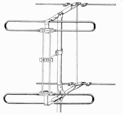
Figure 61. Stacked folded dipoles and reflectors. (courtesy Taco)
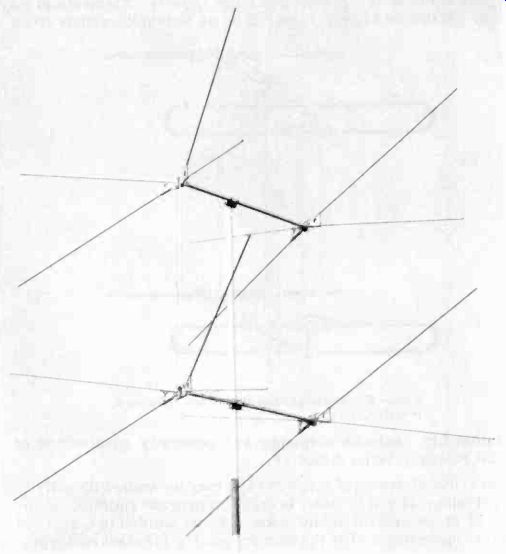
Figure 62. Four-unit double-V stacked antenna. (courtesy Telrex)
Parasitic elements of large arrays may be welded directly to a central metal rod or tube, in order to provide rigidity. A series of these central metal rods may be welded to a vertical metal supporting rod at the proper spacing for stacked arrays.
The metal parasitic element supports do not interfere with the operation of the antenna array, since they are perpendicular to the direction of the horizontally polarized electric field. The active dipole is usually insulated from the metallic support because it is cente RFed. When a delt AMatch is used, the active dipole may be welded to the metallic support. A folded dipole may be welded to the metallic support at the center of its upper sections, and still allow for center feeding of the lower section at the normal open feed points.
5-88 Driven or Phased Arrays. These antenna systems are distinguished from the parasitic type of arrays, in that all of the elements are electrically interconnected. All phased systems are derived from three essential types: collinear, broadside, and end-fire. The elements used in phased arrays are usually a half-wavelength long, because elements of this length are easy to feed and phase. Some systems use elements that are five eighths wavelength long, and some employ shortened elements.
Arrays using elements other than a half-wave long are not very often used for television receiving systems.
End-fire arrays, which give a sharpened pattern in both the horizontal and vertical planes, are difficult to construct and feed. Other systems, although easier to feed, require more space. Difficulty in feeding is brought about by the fact that as antenna elements are moved closer together, radiation resistance decreases. This results in a high standing-wave ratio, with consequent losses when a tuned feed line is employed. If a matched line is used, the antenna system will have a high Q and will operate only over a narrow frequency band. In general, collinear and broadside arrays have a higher impedance, lower Q, than do end-fire arrays. As a general rule, phased array field-patterns are bi-directional, unless special measures are taken to make them unidirectional.
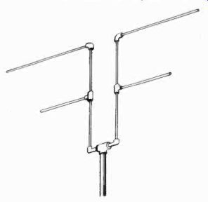
Figure 63. Stub-tuned stacked array.
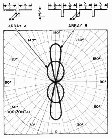
Figure 64. Two types of colinear phased arrays.
5-89 Collinear Arrays. In these arrays the elements are in the same line, and all currents are in phase (Figure 64). Horizontal arrays give horizontal directivity with no change in vertical directivity from that of a simple half-wave antenna. The gain and sharpness of the field pattern depends on the number of half-wave elements and their spacing, center-to-center. Spacing center-to-center is usually one half-wave, that is, the antenna elements are end to end, except for an odd number quarter wavelength phasing section between them.
The gain of collinear arrays may be increased by increasing the center-to-center spacing of the antenna elements. The directivity and frequency characteristics of collinear arrays are such that this type of antenna has found little use in television.
5-90 Broadside Arrays. This basic type of phased array consists of two or more half-wave dipoles, arranged parallel to each other in the same plane (Figure 65). Broadside arrays can be used with either vertical or horizontal elements. If the elements are horizontal; the field pattern is sharpened in the vertical plane, giving low-angle radiation, but the horizontal-plane pattern is the same as for a single element.
The common types of broadside arrays would more properly be described as stacked collinear systems. This is true of the simple Lazy-H, Sterba, Bruce and so-called Billboard array, to name a few. These stacked-collinear broadside arrays have both horizontal (collinear) directivity and vertical (broadside) directivity. The degree of directivity and gain is dependent upon the number, spacing and geometric arrangement of the antenna elements composing the array.
5-91 Lazy-H Antenna. A simple combination of two collinear elements stacked and phased for broadside radiation, results in the so-called "Lazy-H" antenna. It is shown in Figure 66, and derives its name from its resemblance to a reclining "H". The elements are horizontal as shown for television reception. All the half-wave antenna elements are excited in phase by means of the transposed half-wave feeder between the stacked collinear elements. The feed point shown has a high impedance.
5-92 Sterba Array. The horizontal Sterba arrays shown in Figure 67 are another modification of the stacked-collinear broadside array. This system is very nearly the same as the Lazy-H, except that it is a closed circuit. Each of the four "end" dipoles is bent at the center, and adjacent dipoles are then joined permanently. All elements of the Sterba array are interconnected with transposed half-wave feeders so that the currents are in phase. Any type of tuned or matched line may be used to feed a horizontal Sterba array. The impedance at the feed point is high.
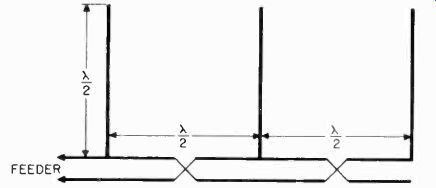
Figure 65. Broadside array.
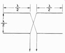
Figure 66. Lazy-H antenna.
5-93 Billboard Array. This type of stacked-collinear broadside array makes use of a metal screen reflector to produce a unidirectional field pattern with sharp directivity in both the vertical and horizontal planes (Figure 68). Billboard arrays consist of at least 4, but rarely more than 64, half-wave dipoles, mounted on a suitable metal screen frame which also functions as a reflector. All dipole elements are fed currents of equal magnitude and phase. Because of their large size, billboard arrays are restricted in use to very short wavelengths. They are useful in television for link-relay communications.
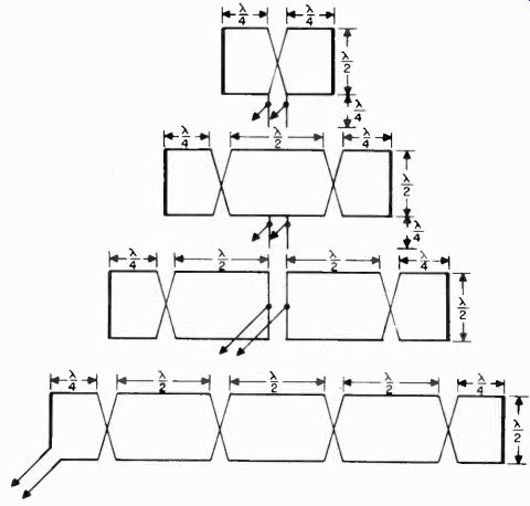
Figure 67. Four types of horizontal Sterba arrays.
5-94 End-fire Arrays. This type of array consists of one or more pairs of parallel half-wave, dipoles, which are fed currents of equal magnitude but of different phase. With certain spacings and with certain phase displacements, such pairs of dipoles known as sections provide field patterns with pronounced directivity. Since this directivity always lies in the plane of the dipole sections, such an arrangement is known as an end-fire array. However, the antenna system is more popularly known as a flat-top array.
The actual field pattern of a flat-top array may be either unidirectional or bidirectional, depending upon the spacing or separation and the phase difference of the two dipoles constituting each section. The degree of directivity is a function of the number of dipole sections, with a maximum limit of 4 sections providing a field pattern sufficiently narrow for most practical purposes.
Flat-top arrays are classified according to their types of feed.
Cente RFed arrays (Figure 69) are usually preferred, because of their symmetry; a quarter-wave matching stub is used to connect the feeder to the array. End-fed arrays (Figure 70) are less critical of adjustment, and often are more convenient to install.
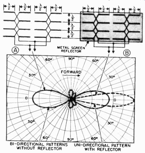
Figure 68. Field patterns of multi-element antenna array. (A) B1-directional
pattern without reflector; (B) Uni-directional pattern with metal screen reflector.
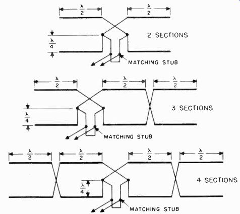
Figure 69. Cente RFed flat-top arrays (top view).
5-95 Long-Wire Arrays. It has been shown that the maximum radiation from a half-wave antenna is broadside to the wire.
However, when a wire is a wavelength or more long, the radiation tends to concentrate more and more off the ends. Such an antenna is called a long-wire antenna. It is more sensitive in its most favorable direction than a hall-wave antenna in its optimum direction. The curve in Figure 71 shows the maximum radiation for long-wire antennas as a ratio to the maximum radiation for a half-wave antenna. This power gain is obtained at the expense of radiation in other directions. Sometimes known as the harmonic antenna, the long wire radiator can be made resonant over a wide range of frequencies with good directivity.
Various combinations of long wire radiators constitute an important branch of directional arrays, which includes the V antenna and its variations, and the rhombic antenna.
5-96 Long-Wire Radiators. Effectively, a long wire radiator consists of a number of half-wavelength dipoles placed end to end in such a way that at any instant current in adjoining half wave sections flows in opposite directions. This out of phase condition is achieved by feeding the long wire radiator at one end (Figure 72). The length of a long-wire antenna is not an exact multiple of a single half-wave antenna, because end effects associated with antennas occur only at the extremities.
The formula for the length of a long wire antenna is:
L = 492 (N 0.05)
where L is length in feet.
N is the number of half-waves on the antenna, and f is resonant frequency in megacycles.
Tuned feeders, Q matching sections and quarter-wave stubs can all be used to feed the long wire antenna at one end.
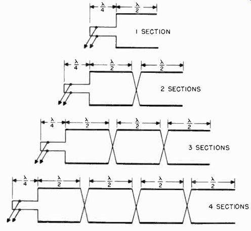
Figure 70. End-fed flat-top antenna arrays (top view). cause of increased
radiation resistance (Figure 73), the long wire antenna tunes broadly.
5-97 The V Antenna. This directional array is composed of two long wire radiators arranged horizontally in a V-Shape (Figure 74), which effectively combines the directional effects of each of the long wires with a pronounced increase in gain. If the two sides of the V are excited 180 degrees out-of-phase, by connecting the two wire feed line to the apex of the V, the lobes add up along the line of the bisector A-B and tend to cancel in other directions.
The V antenna is essentially a bidirectional system, and its gain depends on the length of the wires. The length of the legs of a V beam is not critical, but it is important that both be of the same electrical length. The V antenna is simple to build and operate. It shows considerable gain over a wide frequency range, the gain increasing as the frequency increases. The longer the V, the less is the departure from the optimum enclosed angle, as the frequency is varied (Figure 75). When the antenna is used for extended range television reception, the low-angle radiation characteristics of the antenna may be modified by tilting its plane with respect to the horizon.
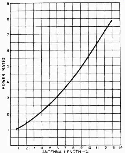
Figure 71. Power gain of long-wire antenna over half-wave antenna.
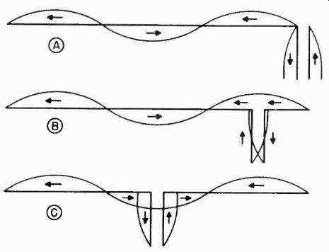
Figure 72. Long-wire antenna, showing current distribution and feed points.
It is preferable to tilt the open V end down, thus increasing the low-angle sensitivity of the antenna. V antennas may be stacked a half-wave apart and fed in phase to secure a broadside effect.
Another arrangement is the formation of a W with two V antennas.
The V beam can be made unidirectional by using a reflector at least a quarter-wavelength in back of the antenna. The height of the antenna above ground should be at least a half-wavelength or better. The method of feed is conventional, any number of tuned and untuned line combinations are adaptable. Because of its size, the V beam is used mainly in rural areas for television reception.
5-98 The Rhombic Antenna. The horizontal rhombic antenna is a form of long wire directional array which provides excellent directivity and high gain. It is an ideal solution to the problem of extended range television reception, provided there exists an adequate radio wave path to the receiving location, and sufficient space is available for its erection.
The rhombic antenna consists of four wires of equal length, arranged in the shape of a diamond and suspended a half-wavelength or more above the earth as shown in Figure 76. The rhombic Is inffect1ve unless each leg (L) is at least two wavelengths long. The larger the ratio of the length of the leg (L) to the operating frequency wavelength (X), the greater the power gain. If the free end is not terminated with a resistance, the rhombic has a bidirectional field pattern. Usually the free end is terminated with a resistance of between 600 and 800 ohm, representing the characteristic impedance of the antenna. The terminated rhombic functions as a non-resonant transmission line without standing waves, with its maximum sensitivity along the axis of the antenna in the direction of the resistance. A practical rhombic antenna design problem is solved step by step in the following discussion.
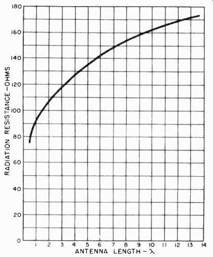
Figure 73. Radiation resistance of long-wire antenna.
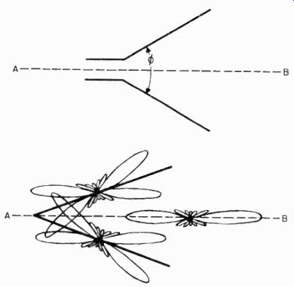
Figure 74. V antenna, and method whereby field patterns of two long-wire
radiators are combined to produce highly directional V antenna field pattern.
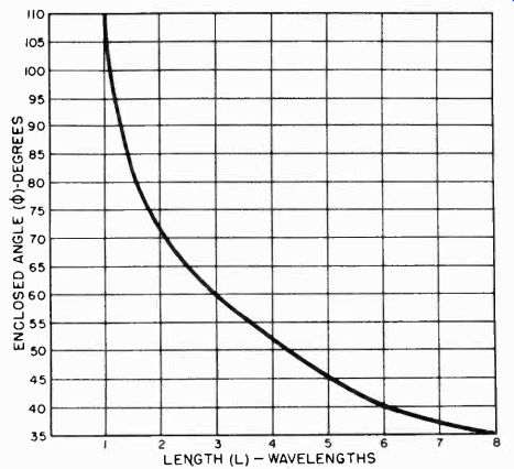
Figure 75 Curve showing change in enclosed angle of V antenna with various
frequencies.
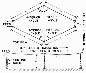
Figure 76. Rhombic antenna.
5-99 Horizontal Wave Angle. The design of a rhombic antenna is influenced by the fact that the maximum sensitivity is not in the plane of the antenna, but is at some angle with respect to ground. This angle of maximum sensitivity above the ground is called the horizontal wave length, and must be considered first.
This is done by estimating the angle from the horizon, formed by sighting the transmitting antenna in question from the proposed receiving location. Since the rhombic is herein being considered for extended range television reception, this angle will be small. It may be more convenient to assume a horizontal wave angle somewhere between 10 and 30 degrees, and incline the plane of the rhombic antenna to compensate for the angle of maximum sensitivity of the resultant antenna.
5-100 Determining Dimensions. Once the desired wave angle has been selected, there are three quantities to be determined: The internal angle, the antenna height and the length of each leg. For a given wave angle there is one set of dimensions for maximum response to signals coming from the desired direction.
These dimensions may be determined mathematically, but for the simplicity they are presented in Figure 77 in chart form.
5-101 A Rhombic Antenna Design. A rhombic antenna can be expected to provide good performance over a frequency range of more than 2 to 1. This means that an antenna designed for a frequency of 100 megacycles will operate properly from 50 to 200 megacycles. Rhombic antennas have an operating range equivalent to the entire thirteen television channels when properly designed.
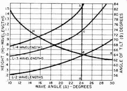
Figure 77. Design chart for rhombic antenna.
Referring to the rhombic design chart for maximum output dimensions (Figure 77) and assuming a horizontal wave angle of 24 degrees, the dimensions can be found as follows:
Draw a vertical line through point a, corresponding to a horizontal wave angle off 24 degrees. Read the intersection of this line on each curve on its corresponding scale:
c = length (L), 3 wavelengths
d = height (H), 0.618 wavelengths
e = internal angle (e), 64 degrees
In all cases, the linear dimensions are in terms of wavelength.
These may be converted to feet by the relation H = 984 = (1 wavelength)
f( Mhz)
for height, and L = 492 (N-0.05)
« Mhz)
(where N is the number of half-waves) for the leg length.
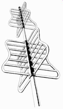
Figure 78. Super-turnstile antenna.
Assuming a design center frequency of 88.7 Mhz., which is close to the geometric center of the television band, H will work out to be slightly less than 7 feet, and L will work out to be 33 feet.
5-102 Television Transmitting Antennas. The super-turnstile antenna (Figure 78) is used almost by all television broadcast stations. This antenna provides an omnidirectional radiation pattern in the horizontal plane, combined with a low vertical radiation angle over a broad band of frequencies six megacycles wide. In place of the half-wave dipoles of the basic turnstile antenna, the super-turnstile is equipped with open sections of metal framework, which act as current sheets. The open sections have the same electrical effect as solid metal sheets of the same size, but not their wind resistance. The open framework is constructed of steel tubing, and vertical members are grounded at both ends. Each bay or stack of the super-turnstile consists of four current sheets arranged in quadrature. The current sheet radiators have inherently broad frequency characteristics. Their large crosswise dimension gives them a low Q and they can be made to reflect a nearly perfect resistive impedance across their associated transmission line over the required six Mhz. Frequency band. This is desirable since the best picture quality is produced by equal transmission of all frequencies in the pass band.

Figure 79. Parabolic reflecting antenna. (courtesy Workshop Associates)
The operation of the individual current sheet elements of the super-turnstile antenna may be compared with that of a dipole shunted by a shorted quarter-wave section of line. With increasing frequency, the dipole becomes inductive while the stub in parallel with it becomes capacitive. Thus, the two reactances tend to cancel and the effective reactance is very low over a broad band of frequencies. The super-turnstile usually consists of three or four bays in order to provide low angle radiation in the vertical plane with a power gain in the horizontal plane. In general, field patterns are similar to those of the basic turnstile described earlier in this section.
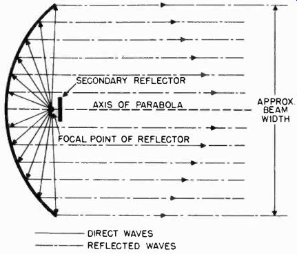
Figure 80. Reflecting action of parabolic surface.
5-103 Television Field Relay Antennas. Since the microwaves used for television field relay broadcasts have characteristics very similar to those of light waves, the parabolic reflector is an obvious directional device for use at these frequencies. A dipole placed at the focal point of a parabolic reflector, as shown in Figure 79, radiates a beam in much the same manner as a searchlight. At the frequencies used for television relays, a six-foot diameter parabola gives a power gain of 30 db or 1000 times. Therefore, a 1 watt transmitter can be made to be as effective as 1,000,000 watts through the use of parabolic reflectors at the transmitting and receiving locations.
This tremendous power advantage is achieved by narrowing the beam to a few degrees, Figure 80. Care in the use of these antennas must be exercised in order to line the antennas up at the receiving and transmitting locations. Jarring or vibration of such antennas during the transmission of a relay broadcast can result in a loss of the signal at the receiver.
5-104 Horn Type Antennas. Some field relay broadcast equipment is designed to operate in the super-high frequency range.
In this equipment, horn type radiators are combined with parabolic reflectors in place of the conventional dipole (Figure 81). The operation of a horn radiator as an electromagnetic directing device is analogous to that of the common acoustic megaphone. However, the throat of an acoustic horn usually has dimensions much smaller than the sound wavelength for which it is used, while the throat of an electromagnetic horn has dimensions which are comparable to the wavelength being used.
A horn type radiator is an adaptation of and is used with wave guides.
5-105 Metal Lens Antenna. This unique antenna provides sharp beams of microwave energy by utilizing the focusing effect of a large number of specially shaped, closely spaced metal plates Figure 81. Electromagnetic horn: left, conical type; center, pyramidal type; right, rectangular type.
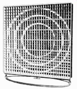
Figure 82. Metal lens antenna.
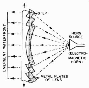
Figure 83. Focusing effect of metal plates of "stepped" construction.
(Figure 82). When used for transmitting, this metal lens receives divergent waves from a point source usually an electromagnetic horn in the rear of the array. As they travel between the parallel conducting plates, the microwaves actually gain speed. By a suitable geometric arrangement of the plates, outer paths are made slightly longer that; paths near the center of the array. In this way, outer waves are accelerated in such a manner that the waves are effectually focused and emerge from the array in a narrow parallel beam (Figure 83). The "stepped" construction of the metal plates provides uniform transmission over a wide band of frequencies, for carrier telephone, television and other microwave services.
An identical array is used as a highly directional receiving antenna, where it funnels microwaves back into an electromagnetic horn and waveguide system for detection, amplification and disposition of the signal. Field patterns less than one tenth of a degree can be obtained with a metal lens antennas.
5-106 Master Antenna Systems. Special consideration must be given to the antenna problem which exists in large apartment houses where it is necessary to operate many television receivers in close proximity. If 100 tenants in a large multiple dwelling owned television receivers, at least 100 individual antennas and transmission lines would have to be installed to operate all the receivers. The maze of antennas and cables on the roof and running down the sides of the building under such a system would violate fire laws, building codes, and possibly even cause damage to the structure itself. Under practical conditions, satisfactory reception for all the receivers in the building would be virtually impossible. With so many antennas arrayed so closely together, interference signals from one set to another would be inevitable. There would be very few locations on the roof where an antenna could be mounted and be free from such disturbances so that the majority of tenants would have to utilize the areas of poor reception.
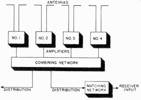
Figure 84. Block diagram of Intra-Video master antenna system.
Master antenna systems are the only solution to this problem.
The first of its kind to be approved by the Radio Manufacturer's Association is the design developed by the Intra-Video Corporation of America. This system is shown in the block diagram of Figure 84. It consists of four major elements:
1. An array of antennas, each critically tuned for a different television channel.
2. Individual band pass amplifiers for each antenna.
3. A mixing and distribution network for combining the signals from all the channels and feeding them to the distribution lines at the proper impedance.
4. Matching networks to couple the receiver impedance to the distribution line as well as to provide isolation between receivers on the same line. The advantages of this system may be realized by an examination of the above features in detail.
5-107 The Antenna Array. Figure 85 shows how the antennas might be oriented in a typical installation to achieve optimum reception on each television channel. One antenna is also provided to cover the FM band so that tenants may operate their FM receivers off the same system. Each antenna is individually cut for the station to be received. Dipoles and folded dipoles are ordinarily used, but if any multi-path reflections are troublesome, a critically directional antenna is used to single out the direct signal or a usable reflection. Each antenna is fed through a separate transmission line to the box containing the amplifier and distribution system. This box may be mounted at a convenient point on the floor below the roof, as is shown in Figure 85, where the unit may be readily serviced.
5-108 The Band Pass Amplifiers. The amplifiers in the Intra Video system are designed to provide uniform band pass over each six megacycle channel. Each channel amplifier consists of seven stages and the response is adjusted to obtain high selectivity. This feature is important for it improves the quality of reception of cheap receivers on the system that do not have good selectivity.
The gain of each amplifier is so adjusted that the signal output from the distribution system is the same level for each channel. This is, of course, the ideal condition for an antenna installation and is seldomly achieved in ordinary systems. It means that the gain control of the receiver, when once set for a station, need not be readjusted for other stations. A well regulated power supply is incorporated in the amplifier to overcome any effects of line voltage fluctuations.
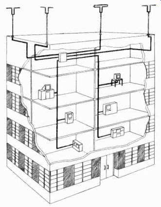
Figure 85. Typical master antenna installation.
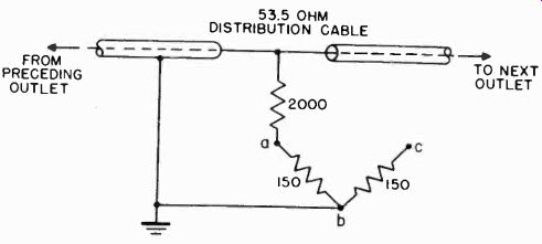
Figure 86. Matching network.
5-109 The Mixing And Distribution System. The output of each channel amplifier is fed to a mixing system which combines the signals of the various stations and feeds them across properly terminated distribution lines. Two distribution lines are provided, each consisting of 52-ohm cable and going progressively from one outlet to another in a continuous string. See Figure 85. As many as 40 to 50 outlets may be used on each distribution line. (Because of successive attenuations in the line, the gain of the amplifiers is set to provide sufficient signal at each outlet according to the number in the system).
5-110 The Matching Networks. The distribution system is terminated at each outlet so that 30 db of attenuation is introduced between the distribution system and each receiver. This brings the signal level down to a proper value to prevent overloading of the input circuits of the receiver. Also, by providing 30 db of attenuation between receiver and cable, there are effectively 60 db of attenuation between any two receivers insofar as transmission of any radiation from one receiver to another is concerned.
The matching network enables the matching of the 52 ohm line to any receiver input impedance. The standard networks in the Intra-Video system have the values shown in Figure 86. By connecting the receiver across points A and C, a balanced 300-ohm input is provided. For unbalanced 72 ohm receivers, points A and C are connected together and the signal taken between AC and B. Other combinations of resistances can be chosen to match receivers with other input impedances.
5-111 Simple Master Antenna System. A simple master antenna system which does not employ booster amplifiers is shown in Figure 87. The number of receivers which can be operated off a single antenna depends upon the signal strength at the antenna. Usually two to four receivers can be operated from one antenna in areas inside the prime service range of a transmitter (within 30 miles). This simple antenna system is suitable for operating several receivers in a sales room or in small, multiple dwellings.
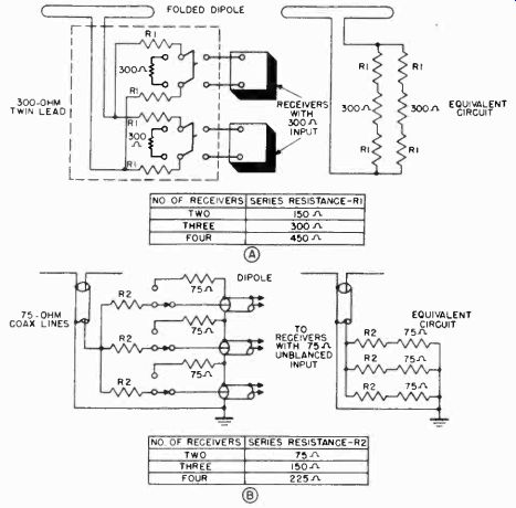
Figure 87. Simple master antenna system.
The network shown in Figure 87A is used for operating receivers with 300 ohm balanced input. The series resistance R1 changes according to the number of receivers on the line.
Values for R1 are shown in the table. A slightly different network is used in Figure 87B for operating receivers with unbalanced, 75 ohm input. Values for the series resistance R2 are shown in the table.
When receivers are coupled across the same antenna, the signal input to each receiver is less than the signal available at the antenna. For two receivers, the signal at each is one half the available signal; for three, it is one third; for four, it is one fourth.
The resistive networks should be made of carbon resistors, mounted on suitable switches. All leads should be as short as possible. It is best to mount the switch assembly in a metal box to provide adequate shielding. If a receiver is removed from the line, a dummy load should be inserted in its place in order not to upset the balance of the system.