Pick-up Control Transmission
4-1
A television station consists of a complete sound broadcasting system and a picture transmission system. Electrically, each system operates independently of the other, even though the sound and picture equipment are usually physically located together. The sound equipment is identical to that found in any radio station, except that it generates a frequency modulated signal and operates on a much higher frequency.
The functions of the picture system are, to pick up the scene to be televised, convert it into a suitable electrical signal, and transmit it. The components of a very simple television system which can perform these functions are shown in Figure 1.
The first block is the camera containing the pick-up tube for converting light into electricity. The camera also contains circuits for controlling the pick-up tube and amplifying the weak electrical signals which it generates. The output signal from the camera is fed to a picture monitor. In this unit the picture is viewed while adjustments are made on the camera to improve signal quality. A synchronizing generator simultaneously sends keying signals to both the camera and the monitor. These keying signals control the motion of the scanning beams in the pickup tube and in the monitor receiving tube. The synchronizing generator also feeds the keying signals to the mixing and distribution amplifier. In this unit, the signal from the camera is combined with the keying signals to form what is known as the composite video or television signal. The video signal is then
fed to the transmitter where it is further amplified and used to modulate the television radio frequency carrier. The modulated carrier is fed to the antenna to be radiated.
At the same time that the picture signal is being formed, the sound accompanying the picture is picked up by a microphone, amplified, monitored, and fed to the sound transmitter. The modulated sound carrier from the transmitter may be radiated from a separate antenna, or from the video antenna.
In succeeding portions of this section, each of the units in the block diagram is discussed in detail. Since the average television station is considerably more complex than the simple system shown in the diagram, after the simple system has been explained, all the accessory equipment found in the average television station will be discussed. This will be followed by descriptions of commercial equipments whose designs are typical of each unit in the television system. Finally, station operation and maintenance will be covered.
PICK-UP HEAD ELECTRONIC VIEWFINDER SYNCHRONIZING GENERATOR ANTENNA MIXING AND PICTURE DISTRIBUTION TRANSMITTER AMPLIFIER MICROPHONE SOUND SOON() MONITOR TRANSMITTER
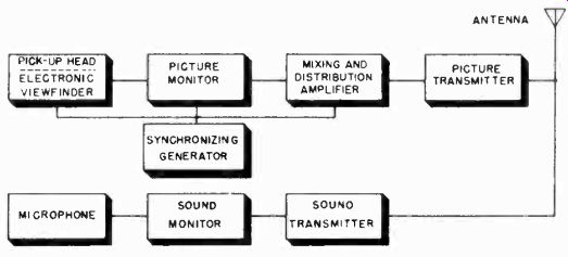
Figure 1. Block diagram of simple television transmitter.
Many of the basic television circuits are common to television transmitters and receivers. The detailed description of some of these circuits was covered in the previous chapter on television receivers. The reader will be referred at times to the receiver chapter for a more complete discussion of a common circuit whenever it is encountered in this description of station equipment.
CAMERA TUBES
4-2
The progress of electronic television transmission can be gaged by the improvements made in the camera pick-up tube.
The quality and interest of television programs as well as the design of the station equipment depend, to a great extent, upon the characteristics of the image forming tube used in the camera.
In Section 2 a complete description was given of the operation of the iconoscope. The iconoscope was one of the first pick-up tubes which overcame the limitations of the mechanical television scanning system and made possible the all electronic television system. Although the iconoscope is one of the earliest camera tubes, it is still superior to other commercial designs with regard to the detail and sharpness of the image it produces. It also has a number of shortcomings which have made it necessary for the industry to develop other types of pick-up tubes.
The poor light sensitivity of the iconoscope makes it necessary to equip studios with tremendous lighting installations. The cost of operation of such lights can be appreciated by the fact that when one New York station was using iconoscope cameras exclusively, the electric power dissipated by the lights exceeded the power required for running the entire station (including studio equipment and the transmitter). Not only is the cost prohibitive, but the heat given off by the lights causes many difficulties. Actors constantly complain of the difficulty of working under the lights in studios equipped with iconoscope cameras.
As a result of the heat generated, expensive air conditioning systems have to be installed.
Even when used with extensive lighting systems, the iconoscope's low sensitivity limits program interest. The lens iris must be run wide open to obtain sufficient picture contrast, thereby reducing the depth of focus and limiting the field of view.
Interesting shadows or lighting effects, which have been so highly perfected in motion pictures, cannot be obtained with iconoscope cameras.
The physical shape and size of the iconoscope presented a problem in cameras designed for remote work. Compact, portable equipment is needed for programs televised outside of the studio. The large size of the iconoscope makes a small camera impossible. Outdoor pick-ups often require telephoto lenses.
The cost of telephoto lenses large enough to cover the area of the iconoscope mosaic is prohibitive.
To overcome the problem of physical size, the orthicon tube was developed. It is smaller than the iconoscope and has a higher light sensitivity. These characteristics make it more suitable for use in portable cameras. Before the war, the orthicon camera was used for most field work while the iconoscope camera was employed in picking up live talent shows and films in the studio.
One other tube was in common use in studio equipment until recent years. This tube is called the image dissector. Its sensitivity and resolution capabilities are about the same as those of the iconoscope.
The first real post-war advance in camera tubes came with the introduction of the image-orthicon by RCA. This tube is over 100 times as sensitive as the iconoscope and is considerably smaller in size. Unfortunately, it is not capable of producing as sharp and as detailed a picture as is the iconoscope.
Nevertheless, because of its high sensitivity, the image-orthicon is now preferred for use in both outdoor and studio camera equipment. A few stations which were equipped with iconoscope cameras and the necessary light installations, continue to use iconoscope equipment for studio programs. The best images are still produced with the iconoscope.
Most new stations are not investing in expensive lighting installations and iconoscope equipment, preferring to compromise on the slightly inferior pictures obtained with the image orthicon.
These stations use the image-orthicon camera for outdoor and studio work. In some instances it is also used for film pickups, although in the majority of cases a separate iconoscope camera is provided for this purpose.
The television camera tube problem appears to be resolving itself in the following manner. Most stations are buying image orthicon cameras for studio and outdoor use. If better resolution of picture is desired for studio work, the station must invest in iconoscope cameras and an expensive lighting installation. The iconoscope camera is now used almost exclusively for televising from films. In film pick-up equipment the light concentrated on the mosaic is sufficiently intense for use with the iconoscope.
The operation of the iconoscope was covered in Section 2. The following pages contain descriptions of the other types of camera tubes.
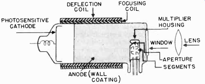
Figure 3. Construction of the image dissector.
4-3

Figure 2. The image dissector. (courtesy Farnsworth)
The Image Dissector. The image dissector (Figure 2), was invented by P. T. Farnsworth and was used extensively in studio and film cameras before the war. Its low sensitivity to light and the advent of more sensitive tubes now limit the use of the image dissector to film cameras where the light level is high enough to utilize the excellent resolution capabilities of the tube.
The elements of an image dissector tube are shown in Figure 3. The object to be televised is projected through a window and focused on a photosensitive cathode. The number of electrons released from any point on the photocathode depends upon the intensity of light at that point. These photoelectrons are accelerated as an "image cloud" down the length of the tube toward the aperture. The silver layer on the inner surface of the tube acts as the positive anode which pulls the electrons from the cathode. A focusing coil surrounds the tube and keeps the electrons moving in a straight path. The entire electron image is then moved both horizontally and vertically by means of two deflection coils also surrounding the tube. In this way the image is moved past the aperture, permitting electrons to enter it in a chain of pulses. In other words, instead of moving a single beam of electrons to scan the image on the mosaic as is done in the iconoscope, the entire electron image in the dissector is moved back and forth past a small opening at the horizontal and vertical scanning frequencies.
Since only a very small fraction of the total image is in front of the scanning aperture at any instant, most of the light (and the photoelectrons released from the photocathode by it) does not contribute to the output signal. To overcome this inherent insensitivity, a "multiplier" section is added near the aperture.
The electrons which pass through the aperture excite secondary electrons in the "multiplier", resulting in a signal which is several thousand times stronger. Even with this multiplier section and the large size lenses which are used with the tube to collect as much light as possible, the image dissector remains a very low sensitivity tube in comparison to other types.
4-4 The Orthiconoscope (Orthicon). The Orthiconoscope (orthicon for short) is a camera tube of the storage type like the iconoscope. The image is stored on a mosaic until the scanning beam converts it into an electrical signal. The orthicon uses a scanning beam of much lower velocity than does the iconoscope so that no secondary electrons are emitted. This is advantageous, for there are no spurious secondary electrons to fall back on the mosaic as is the case with the iconoscope. This in turn eliminates the necessity for shading signals to correct for spurious secondary emissions. In the absence of secondary electrons in the orthicon, the scanning electrons themselves are collected to form the video signal.
The structure of the orthicon is shown in Figure 4. The image to be televised is focused on a plate which is transparent to light. On one side of this plate is a photosensitive surface or, mosaic. An electron image is stored on this mosaic. The scanning beam, coming from the other direction, moves across the mosaic in the same manner as in the iconoscope. If the scanning beam impinges upon a point on the mosaic which has previously lost its charge (caused by light falling on it), several electrons are collected by the mosaic from the beam to neutralize the point. In this manner, each point on the mosaic is returned to an equilibrium condition by the necessary amount of electrons. These electrons set up a varying potential on the mosaic and so constitute the video signal.
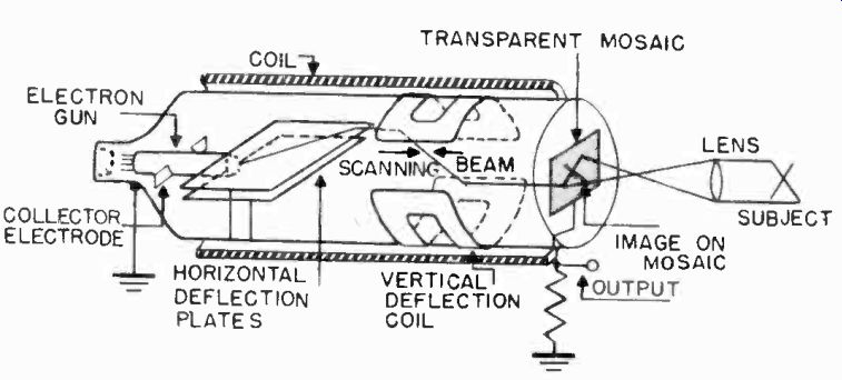
Figure 4. Construction of the Orthiconoscope.
The orthicon's physical shape gives it several advantages over the iconoscope. The optical image and scanning beam strike the mosaic along the tube's axis. No keystoning distortion takes place as in the iconoscope. The tube is about four inches in diameter and about 20 inches long, and the mosaic is 2 by 21 inches. The orthicon lends itself to mounting in smaller, more compact cameras for outdoor work. The smaller mosaic enables the use of smaller lenses than are required with the iconoscope.
The orthicon is about 10 to 20 times as sensitive as the iconoscope. Its noise level is higher and its resolution lower. While some stations are still using cameras with orthicon tubes, the newer image orthicon is rapidly making the orthicon obsolete.
4-5 The Image Orthicon. The most sensitive commercial camera tube developed to date is the image orthicon. It is about 100 times as sensitive as the iconoscope and can pick up a scene lighted only with a candle. The images produced by the image orthicon lack the detail of those produced by the iconoscope, and its signal to noise ratio is lower. It is not the best camera tube for operation in the studio where the light level can be made high enough to permit the use of a less sensitive, but less noisy tube like the iconoscope or the image dissector.
The great sensitivity and small size of the image orthicon make it an extremely valuable tube for use in remote pick-up equipment, which must often be operated at very low light levels.
The tube is quite small, as shown in Figure 5, and has a target Figure 5. The image orthicon. (courtesy RCA) area only 1-1/4 inches in diameter. It thus makes possible light, portable cameras and permits the use of turrets carrying lenses of several different focal lengths. This is advantageous in covering outdoor events, such as football games, where it is desirable to switch very quickly from a telephoto lens to a wide angle lens. The tube's high sensitivity also allows the lens to be stopped down to achieve greater depth of focus. An image orthicon camera used in field pick-up equipment and equipped with a turret lens is shown in Figure 6.
The image-orthicon tube consists of three sections: The image section, the scanning section, and the multiplier section. These are shown in Figure 7.
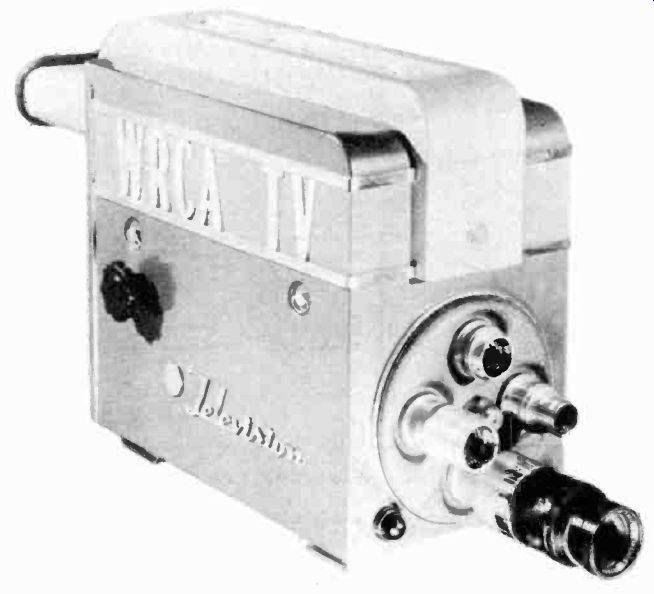
Figure 6. Image orthicon camera. (courtesy RCA)

Figure 7. Construction of the image orthicon.
4-6 The Image Section. The image section is shown in greater detail in Figure 8. It consists of a photocathode, an electron lens system, and a target. The camera lens focuses an optical image on the front of a translucent photocathode which is found on the inside of the large section of the glass envelope. Photoelectrons are emitted from the rear of the photocathode. Their distribution and number correspond to the light rays which fall on the front of the photocathode.
GRID 6(-320 V) PHOTO-CATHODE (-400V) SCENE BEING TELEVISED LENS PHOTO-EMISSIVE COATING / MAGNETIC FIELD YPICAL HELICAL ELECTRON PATHS (EXAGGERATED) TARGET SCREEN APPROXIMATELY GROUND POTENTIAL TARGET
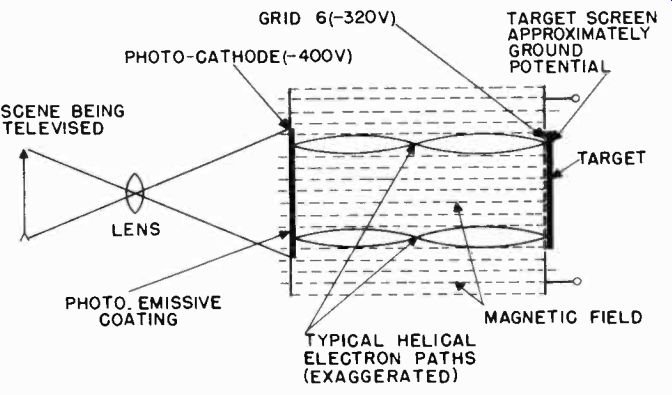
Figure 8. Multiplier section of the image orthicon.
An electrostatic field, set up by the potential difference existing between the photocathode and the target, combines with the longitudinal magnetic field to focus the electron image on the front surface of the target. The target is a very thin glass plate, in front of which is located a fine mesh screen. The photoelectrons traveling toward the target, having been accelerated by approximately 400 volts, pass through the screen and strike the target, causing secondary electrons to be emitted.
These secondary electrons are collected by the fine mesh screen and are returned to ground. This leaves a positive charge on the target which corresponds to the electron emission from the photocathode. Since the number of secondary electrons emitted by the target is greater than the number of electrons which strike the target, a charge configuration is produced on the target which is several times as great as the original charge emitted by the photocathode. This charge Is most positive at the points corresponding to the brighter portions of the picture.
The purpose of the fine mesh screen is to insure that the secondary electrons will be collected rather than be allowed to fall back on the target again to produce spurious signals. This effect is common in the iconoscope and requires that external correcting signals be injected into the video signal.
4-7 The Scanning Section. See Figure 9. The electron gun of the image orthicon operates in the same manner as does the electron gun in a conventional cathode-ray tube. The voltage on grid 2 determines the velocity with which electrons leave the gun. The potential on grid 1 limits the beam current. The combination of voltages on grids 2, 4, and 5, and the longitudinal magnetic focusing field, causes the beam to be focused upon the rear surface of the target. Grid 3 has little effect during the forward travel of the electron beam.
DEFLECTING COILS FOCUS COIL TYPICAL ELECTRON PATH GRID I (-20V) GRID 3 (+210V) AC/ GRID 2 (+210V I\711.GRID 4(WALL COATING)(+120V) GRID 5 (DECELERATOR)(+25V) CATHODE A/ (0-V) X6.3)/. X A.C. TARGET (APPROX. 0V ) ALIGNMENT COIL (INDICATED VOLTAGES ARE APPROXIMATE)
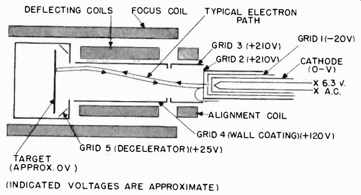
Figure 9. Scanning section of the image orthicon.
Since the target mesh is operated at ground potential, or even slightly negative, the electron beam composed of negative electrons is repelled by the negative charge on the target and never reaches it. The beam actually turns around and travels back toward the electron gun. This returning beam eventually determines the character of the output video signal.
It will be remembered that light from the original scene was focused on the photocathode and caused photo-electrons to be emitted. These electrons were accelerated, and passed through the tube to strike the target. Due to the physical characteristics of the target, each incident photo-electron caused the emission of several secondary electrons which were collected by the target mesh. Thus the final effect was to leave those sections of the target corresponding to the white portions of the picture more positive with respect to the mesh than those corresponding to dark portions of the picture. This charge pattern is transferred substantially unchanged to the rear, or scanned side, of the target.
By correctly setting the potential of the target mesh, the electron-beam can be made to approach the target at a velocity which will enable those sections of the target representing black portions of the picture to repel the beam. The beam will only supply electrons to neutralize the charge deficiency on those more positive portions corresponding to whiter sections of the picture.
Thus, if the beam is scanned over the target, part of the beam will be collected by the target, and part will reverse its direction and be accelerated back toward the electron gun structure.
The amount of current in the return beam at a given instant will depend upon the charge on the portion of the target being scanned at that time. The current variation in the return beam is such that maximum current corresponds to black in the picture, while minimum current corresponds to white in the picture.
Scanning is produced by passing sawtooth scanning currents through the horizontal and vertical deflection coils which surround the tube. These coils are located inside the focus coil.
The focus coil provides the longitudinal magnetic field which passes through the scanning and image sections. It is important that the scanning fields do not extend to the target and image section. Any scanning action in the image section will result in picture blurring due to displacement of the photo-electrons. To prevent this loss of resolution, a metal shield is placed around the target end of the image section.
Sections of the target which have been scanned have no positive charge remaining (assuming proper beam current adjustment), and are in the same condition as the portions which correspond to black. The scanning beam can not be permitted to strike the target during sweep retrace times, since this would cause the charge pattern to be neutralized and cause black lines to appear in the picture. Negative pulses are used to repel the beam from the target during horizontal and vertical retrace times. When the pulse inserted in the picture for target blanking is properly set, it provides a definite black picture reference level in the video signal.
4-8 The Electron Multiplier Section. The electron multiplier section is shown in Figure 10. As the return beam from the target enters the region of grid 3, the beam tends to spread. In so doing it strikes the outer surface of grid 2 rather than returning through the hole from which the forward beam came.
Grid 2 is also called the 1st dynode. The dynodes are coated with a material which enhances their secondary electron emitting characteristics. For each incident electron in the return beam which strikes the 1st dynode, several secondary electrons are emitted. By passing the secondary electrons to the next dynode, the number of secondary electrons is further increased.
For each secondary electron emitted from the first dynode, many more secondary electrons are emitted from the second dynode. Thus each dynode multiplies the number of electrons.
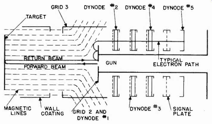
Figure 10. Electron Multiplier Section of the image orthicon.
The combined action of the dynodes results in a considerably stronger signal than that originally produced on the photocathode.
It is this multiplier arrangement in the image orthicon which gives the tube its high sensitivity.
When the electrons in the return beam cause the emission of several secondary electrons from the first dynode, the secondary electrons find their way into the space between dynode 1 and grid 3 immediately, or, after falling back to the dynode 1 surface a few times. When they finally do reach the space, they are subjected to an accelerating field produced by dynode 2 which is operated at approximately 500 volts. The accelerating field causes them to pass through a screen into the dynode 2 vanes.
The voltage on grid 3 is adjusted for optimum picture quality, and controls the number of electrons landing on dynode 2. The dynode vanes are flat and radiate from the center of the tube near the gun in "wheel" fashion, as shown in Figure 11.
An electron entering the vane structure perpendicularly to its plane must always strike one of the vanes. The electron, in striking the vane, excites further secondary emission. The secondary electrons are then accelerated to dynode 3, then 4 and 5. A typical electron path from one dynode to the next is shown in Figure 10. The final multiplied current is collected by the signal plate. The current is passed through a load resistor and constitutes the output video signal.
4-9 Monoscope Tubes. In tubes such as the iconoscope and image orthicon, the video signal is created by an electron beam
bombarding a photosensitive plate. The plate emits secondary electrons in varying numbers as the beam bombards successive points on its photosensitive surface. A photosensitive plate, or any surface which gives off secondary electrons, can be used to generate a television signal.
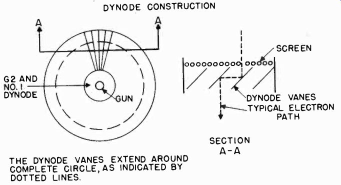
Figure 11. Construction of the dynode vanes in the image orthicon.
This principle has been used in another television camera tube of simple construction. This tube is known as a monoscope (also called a phasmajector or a monotron), and is built into a simple camera which produces a fixed image used for testing equipment in the television station. A monoscope camera is sometimes used in receiver manufacturing plants as a source for a test picture when no television signal is otherwise available.
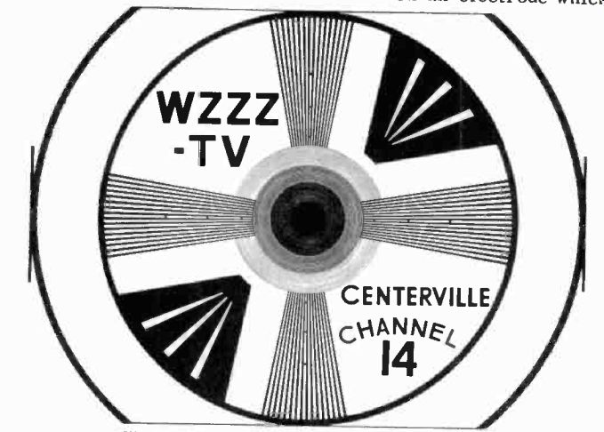
Figure 12. Pattern obtained from monoscope tube.
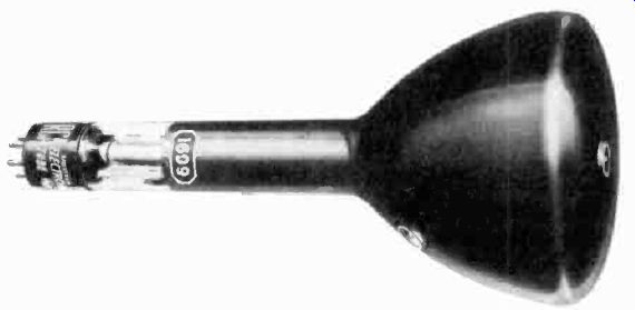
Figure 13. Monoscope tube. (courtesy RCA)
The picture obtained from a monoscope is shown in Figure 12.
This pattern is printed on an aluminum plate with ordinary printer's ink. The back of this plate may be seen in Figure 13.
The carbon in the ink and the aluminum have different secondary emission characteristics. The aluminum gives off about twice as many secondary electrons as the carbon when bombarded by an electron beam.
The printed plate is mounted in the tube where an electron beam scans the printed half-tone pattern, causing greater secondary emission from the aluminum surfaces (the white portions of the picture) than from the black printed portions. The varying secondary electrons are collected on an electrode which consists of a conductive coating on the wall of the monoscope tube. The video signal is developed across a load resistor connected between the coating and ground.
Deflection of the scanning beam is achieved magnetically with horizontal and vertical deflection coils. These coils are mounted in a yoke which fits over the neck of the monoscope tube. The electron gun is similar to that found in conventional cathode-ray tubes. Electrostatic focusing is used.
The monoscope has a much higher efficiency than tubes utilizing photosensitive surfaces. Signals as high as 4 or 5 millivolts are obtained across the output load. The detail of the image is good and is limited only by the cross-sectional area of the scanning beam and the quality of the half-tone used to print the pattern. Most monoscope tubes are capable of 500 line resolution, which is sufficient to test the full capabilities of television equipment as to contrast and resolution. The ruled lines on the pattern of Figure 12 are used to check the linearity of deflection circuits.
The chief advantage of a monoscope camera in a television station or receiver factory is that it offers a standard reproducible image for comparing the performance of equipment over a period of time. No source of lighting is required. Consequently, there are no variations in illumination and an image of constant contrast is obtained.
CAMERA CIRCUITS
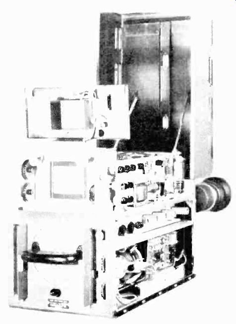
Figure 14. Pickup head and electronic viewfinder. (courtesy DuMont)
4-10 The following description of camera circuits applies to designs using the type 2P23 image-orthicon tube which is used inmost of the new television station cameras. Circuit designs differ somewhat in equipment offered by the various manufacturers, but the basic principles are the same. The description of the image orthicon camera circuits covers most of the circuits required for other types of camera pick-up tubes.
The television camera is in reality two units. One is the pickup head containing the image orthicon and its associated video, sweep, and power supply circuits. The other is the electronic view finder containing a miniature television receiver on which the camera operator watches the scene being televised. These units are shown in Figure 14. In pre-war cameras, optical viewfinders were often used. However, since the human eye and the image orthicon have different color responses, with an optical viewfinder the camera operator sees a picture which does not correspond to the one transmitted. The electronic viewfinder enables him to see the picture exactly as it is sent out over the air.
Some cameras are equipped with a third unit which is housed in a separate case. This unit is known as the camera pick-up auxiliary. When in use it is placed close to the camera. The camera pick-up auxiliary contains the power supply and synchronizing circuits for the camera which need not be housed in the pick-up head itself. By placing these circuits in an external case, the weight and size of the camera are kept to a minimum.
4-11 The Video Circuits. A video amplifier system is located in the pick-up head, along with the camera tube and the sweep circuits. Figure 15 shows the circuit of a typical video amplifying system for use in a television camera.
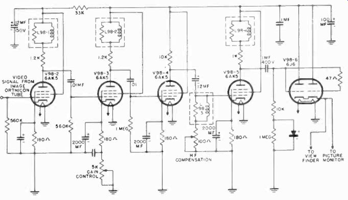
Figure 15. Circuit of video amplifier used in image orthicon camera.

Figure 16. Block diagram of video amplifier used in image orthicon camera.
The video signals appearing on the final multiplier of the image orthicon tube are coupled to the grid of the first video amplifier, V98-2. The video amplifier stages consist of 6AK5s, V98-2 through V98-5, and one 616 tube, V98-6, as shown in the block diagram of Figure 16. The first two stages are shunt-peaked to produce a frequency response flat to 8 megacycles (the response of the video amplifier in station equipment is generally made greater than the required 4 mhz to insure that no loss in picture quality will occur). The third stage is coupled to a high frequency compensation network used to accentuate high frequency response to compensate for high frequency losses which occur in the input coupling network. V98-5 is a voltage amplifier stage feeding V98-6, a 616 double triode, connected as a cathode follower output. The cathode follower is used to match the high impedance of the last video amplifier stage to the low impedance of the transmission line which connects it to the picture monitor.
A manual gain control is provided in the cathode of V98-3 to accommodate the various signal output levels of different orthicon tubes and/ or different light conditions.
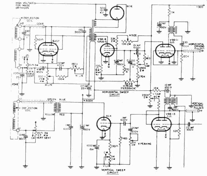
Figure 17. Vertical and horizontal circuits for use with image orthicon.
4-12 The Sweep Circuits. The camera tube sweep circuits are similar to those used in a television receiver. A typical camera sweep circuit is shown in Figure 17. Horizontal and vertical synchronizing or driving pulses, already separated and shaped, are received from the camera pick-up auxiliary unit. The horizontal pulses trigger one-half of a 6J6 tube (V98-11), used as a blocking oscillator. The blocking oscillator pulses are applied to the second section of the 6J6, which is a discharge tube, producing a sawtooth voltage on discharge condenser C-1. This sawtooth is applied to the grid of the 6BG6-G amplifier tube which amplifies the sweep voltage and feeds it to the camera tube yoke through a coupling transformer. A 6AS7 tube is used as a damper. High voltage for the image-orthicon is derived from a kickback circuit (Section 3) in the horizontal sweep output stage.
The vertical synchronizing pulses trigger one half of a second 6J6 tube (V98-13) also used as a blocking oscillator. The blocking oscillator pulses are applied to the second section of the tube which produces a sawtooth voltage at the vertical frequency.
The resultant sawtooth is fed to the grid of a 6C4 sweep amplifier. This stage is transformer coupled to the vertical deflection coils.
4-13 The Electronic Viewfinder. The electronic viewfinder is mounted in the pick-up head. Its purpose is to permit the camera operator to see the scene being televised. The viewfinder is actually a television receiver without radio frequency circuits. A block diagram of the viewfinder is shown in Figure 18.
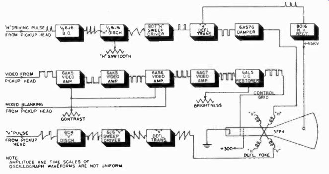
Figure 18 Block diagram of circuits of electronic viewfinder.
It contains the same type of sweep circuits used to deflect the beam in the image-orthicon tube. In the camera viewfinder the beam traces out the picture on a small television receiving tube, usually a 5FP4. The 5FP4 is a five inch magnetic cathode-ray tube identical to those used in television receivers, except for its small size. The picture on the tube is 3 x 4 inches in size.
In the viewfinder there is no need for RF and IF circuits or a video detector to detect and amplify the video signal in the television receiver. The video signal is fed directly from the camera to the viewfinder. Several video amplifier stages bring the video signal up to a level sufficient to drive the grid of the viewfinder tube.
4-14 The Camera Pick-Up Auxiliary Unit. The camera pick-up auxiliary unit serves as the connecting link between the picture monitor and the camera. Its physical location in the system is such that it is less than 30 feet from the camera, while up to 1,000 feet of cable may be used between the auxiliary and the monitor control. The pick-up auxiliary units serves four functions:
1. It provides regulated positive and negative d-c voltages for the pick-up unit in the camera.
2. It provides adjustable regulated current for the image orthicon tube focus coil.
3. It provides centering voltages for the pick-up unit and viewfinder.
4. It provides vertical and horizontal synchronizing pulses for the pick-up unit and the viewfinder.
THE SYNCHRONIZING GENERATOR
4-15 In television stations, the synchronizing generator is the "brain center" which furnishes the timing pulses to the studio and film cameras, to the picture monitors, and to the mixing amplifier (which adds the synchronizing pulses from the sync generator to the video signal generated in the camera). Sync generators are also used in laboratories and factories in conjunction with a monoscope camera to furnish a complete video signal which can be used for the development and production testing of television receivers.
The synchronizing generator furnishes all of the timing pulses required in a complete television system. These pulses are accurately timed with relation to each other. Their shape and length is carefully controlled in accordance with the standards set up by the FCC to assure stable operation of television receivers. The waveshape and time relation of these pulses is shown in Figure 19. This is the standard television signal whose components were discussed in Section 2.
Depending upon the commercial design, one or more of the following signals are supplied by the sync generator:
1. Horizontal driving signal This consists of short-duration, square wave pulses at the horizontal scanning frequency (15,750 cycles). These pulses are used to trigger the sawtooth sweep generator (in the camera), which supplies the horizontal scanning voltage for the pick-up tube.
2. Vertical driving signal This consists of square wave pulses of longer duration than the horizontal pulses. These pulses occur at the vertical scanning frequency (60 cycles).
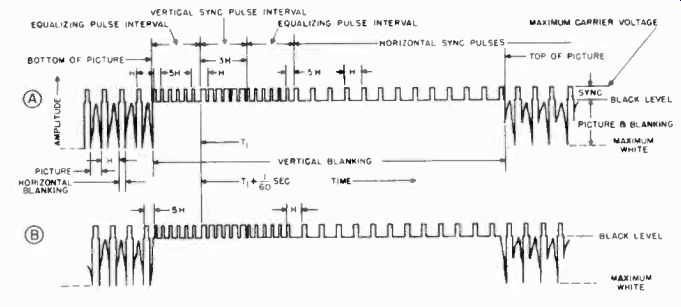
Figure 19. Standard F.C.C. television signal.
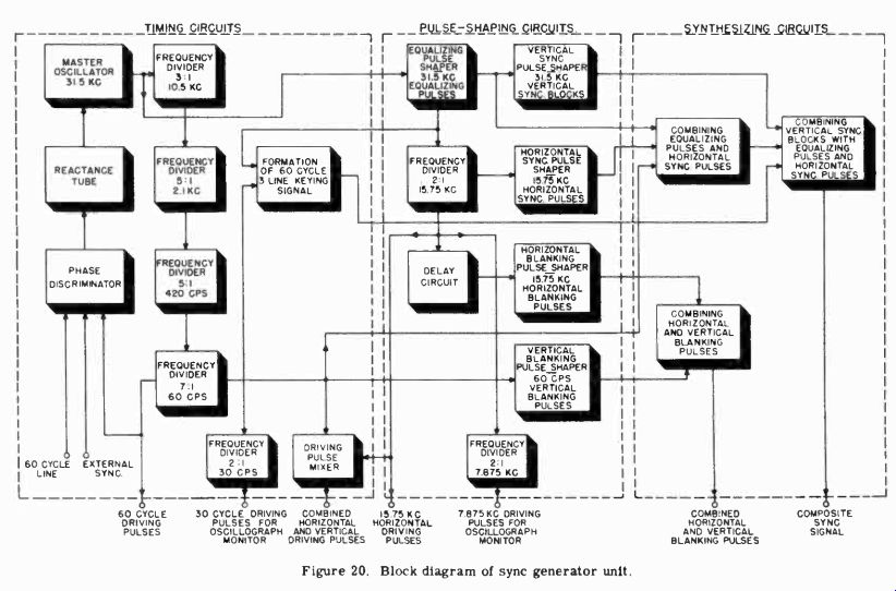
Figure 20
They are used to trigger the sawtooth sweep generator (in the camera) which supplies the vertical scanning voltage for the pick-up tube.
3. Mixed driving pulses Some sync generators combine the vertical and horizontal driving pulses, instead of feeding them separately to the camera. This eliminates one co-axial line which must be run from the generator to the camera. Separator circuits are then employed in the camera, or camera pick-up auxiliary, to separate the vertical and horizontal driving pulses.
4. Synchronizing signal This is the signal shown in Figure 19, which must be added to the camera picture signal before it is transmitted in order to synchronize the scanning action in the receiver. It is a composite signal consisting of (a) short duration, horizontal synchronizing pulses at 15,750 cycles; (b) longer duration, vertical synchronizing pulses of the "serrated" type at 60 cycles, and (c) a series of six short-duration, equalizing pulses just preceding each vertical pulse interval and six more following it.
5. Blanking signal This signal is added to the transmitted video signal in order to blank out the return trace in the receiver picture tube. It consists of square wave pulses at the horizontal scanning frequency (15,750 cycles) and the vertical scanning frequency (60 cycles). These pulses are of longer duration than the synchronizing pulses, and their amplitude extends down to the black level of the video signal. They form the "pedestals" on which the synchronizing signals are placed and also blank out the scanning beam during the retrace period.
6. Oscillograph monitor driving signals These signals are pulses at half the horizontal (7,875 cycles) frequency and half the vertical (30 cycles) frequency. They are used to trigger the sweep circuits in the oscillograph monitors which are located in the picture monitor. Oscillograph patterns which are two lines or two fields in length are thus obtained.
Sync generators are divided into three main sections as shown in the block diagram of Figure 20. The first section contains the timing circuits while the second section contains the pulse shaping circuits. The third section synthesizes the various pulses into the composite sync and blanking signal. The timing unit generates keying signals which occur at frequencies corresponding to the different pulses in the video signal. The timing unit also provides a means whereby these frequencies (which are all derived from a single master oscillator) maybe "locked in" either with the local 60 cycle power line frequency or with some other external source, such as a remotely generated synchronizing signal. The pulse-shaping unit forms the sync blanking and equalizing pulses. These pulses are then combined into a composite signal by "keying" the shaper circuits with signals from the timing unit.
4-16 The Timing Circuits. The timing of the vertical synchronizing pulses must be very accurately related to the timing of the horizontal synchronizing pulses if accurate interlacing of the two fields of each television frame is to be achieved. In Section 2, the interlaced scanning system was explained. The half-line spacing between fields was achieved by inserting equalizing pulses before and after the vertical sync pulse.
If the vertical and horizontal sync pulses and the equalizing pulses are not properly related to one another a distorted picture results. It is therefore convenient to relate them to one single continuous frequency which is a multiple of their fundamental frequencies. This multiple frequency is generated by the master oscillator in the synchronizing generator. All the signal components of the sync generator are derived from this oscillator by frequency divider and wave-shaping circuits. By relating the timing of all sync signal components to this master oscillator, stable and accurate timing of the pulses is achieved.
4-17 The Master Oscillator. The master oscillator is a stable sine-wave oscillator whose frequency is locked to the 60 cycle power line or to a remotely operated synchronizing generator.
Locking the master oscillator to the power line insures synchronization between the television scanning circuits and film cameras which are also locked to the power line by synchronous motors. It also eliminates the possibility of 60 cycle hum patterns drifting through the picture, should this hum originate in the over-all television system. When a program is received from a remote pick-up, the studio sync generator is locked to the remote sync generator. This permits switching from the remote program to the local studio program without disturbing the synchronization of receivers.
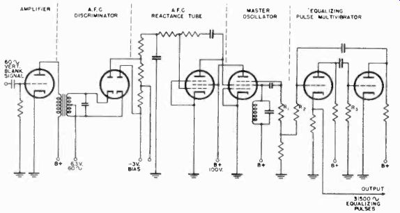
Figure 21. Master oscillator and a-f-c circuits of sync generator.
The master oscillator frequency is 31.5 khz, which is also the frequency of the equalizing pulses. Hall this frequency is the horizontal frequency of 15.75 khz. If 31.5 khz is divided successively by 3, 5, 5, and 7, a 60 cycle frequency results which is the frequency of the vertical synchronizing pulses. Thus, with suitable frequency divider circuits, a timing signal can be obtained from the master oscillator for each type of pulse.
A sine-wave oscillator, such as the Colpitts (Section 3) or the Transitron is used to generate the master oscillator frequency.
The drift stability of the oscillator is not as important as the cycle-to-cycle regularity which is required to produce a television picture with straight vertical edges. Oscillator drift is prevented by locking the oscillator to the power line with an automatic frequency control system which will be explained later.
A typical master oscillator circuit using a Transitron oscillator is shown in Figure 21. The Transitron oscillator can be recognized by the fact that a pentode is always used and the positive voltage on the screen is greater than that on the plate.
A negative voltage is applied to the suppressor through resistor R-1. Under these conditions, the tube offers a negative resistance to the tuned circuit. In other words, a decrease of screen voltage causes an increase in screen current and vice versa, due to the relative effect of the suppressor and screen grid fields. The advantages of the Transitron are its simplicity, and the ease with which its frequency can be controlled by an injected signal.
Automatic frequency control of the master oscillator is achieved with the discriminator and reactance tube circuits shown in Figure 21. The phase discriminator compares the 60 cycle power line frequency (6.3 volts a-c) with the 60 cycle output of the frequency divider chain in the master oscillator. The discriminator develops a direct-current output whose value depends upon the relative phase of the two input signals to the discriminator. This d-c current is fed to the reactance tube which is connected across the tuned circuit of the Transitron oscillator.
The gain and phase relationships of the reactance tube are such that they produce a current and voltage in the plate circuit, equivalent to an inductive or capacitive reactance. This reactance is capacitive or inductive, dependent upon the amplitude of the fluctuating d-c signal on the grid. The variable reactance, connected across the tuned circuit of the oscillator, causes its frequency to vary accordingly. If the master oscillator and power line are in phase, there is zero output from the discriminator. If the two move out of phase, a d-c control voltage is obtained from the discriminator which changes the reactance across the oscillator tank circuit, pulling the oscillator back to its correct frequency.
4-18 The Frequency Divider Chain. The frequency divider chain consists of a number of stages which divide the master oscillator frequency into submultiples of the vertical and horizontal sync frequencies. Three types of divider circuits are used for this purpose. These are the multivibrator, the blocking oscillator, and the counter circuit.
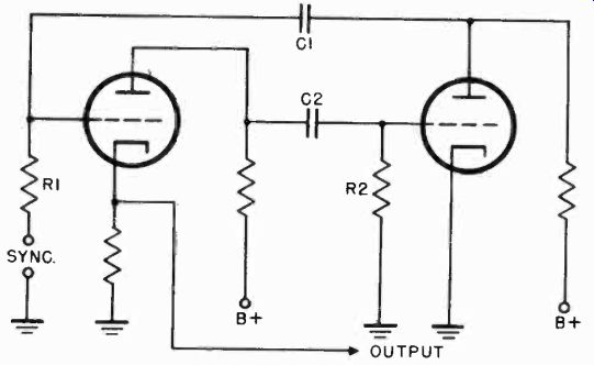
Figure 22. Multivibrator frequency divider.
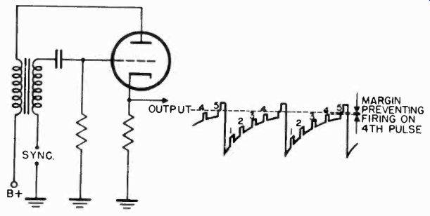
Figure 23. Blocking oscillator frequency divider.
The multivibrator divider is an oscillator composed of two resistance coupled amplifiers. The output of the second stage is fed back to the input of the first stage to support oscillation.
The oscillator frequency is determined by the time constants R1-C1 and R2-C2 (Figure 22). If a pulse is fed into the grid of the first stage, it will synchronize the oscillator on a sub-multiple of the pulse frequency. The sub-multiple at which it operates depends upon the time constants of R1-C1 and R2-C2.
The blocking oscillator divider is a little more stable than the multivibrator because it substitutes a stable transformer for one of the tubes. The blocking oscillator divider is shown in Figure 23. The voltage on the grid during one cycle of oscillation is also shown in the figure. Frequency division is obtained by applying a signal to the grid of the oscillator and setting the R-C time constant in the grid circuit to a sub-multiple of the incoming signal. The oscillator then operates on a lower frequency than the incoming signal.
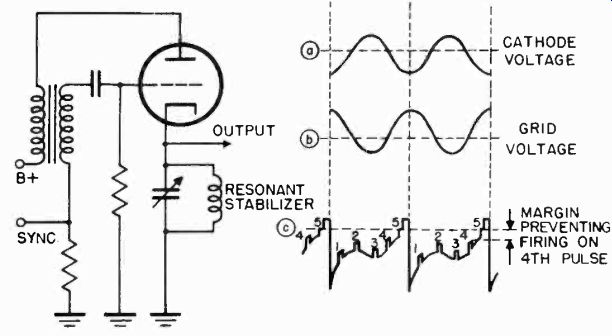
Figure 24. Stabilized blocking oscillator frequency divider.
As shown on the grid characteristic, only the fifth incoming pulse occurs sufficiently far up on the grid curve to overcome the cutoff bias on the oscillator and cause it to produce a pulse.
For every five pulses coming into the oscillator, only one pulse is produced by the oscillator. Note that the fourth pulse is almost sufficient to trigger the oscillator. Incorrect frequency division occurs if drift in the oscillator stage permits the fourth pulse to rise above the cutoff voltage. A stabilized blocking oscillator prevents this by providing a greater margin of safety between the amplitude of the next to the last pulse and the cutoff voltage.
A stabilized blocking oscillator is shown in Figure 24. This circuit is the same as the blocking oscillator circuit shown in Figure 23, except that a tuned circuit is placed in the cathode lead.
The resonant circuit in the cathode is shock excited by the pulse of grid current that flows through it during the positive grid portion of the cycle. The voltage that appears on the cathode is a damped oscillation such as shown in Figure 24a. This damped oscillation appears on the grid 180 degrees out of phase as shown in Figure 24b. This transient voltage, which occurs each time the oscillator conducts, is added to the grid characteristic as shown in Figure 24c. The effect is to move the next to the last sync pulse further below the cutoff voltage, while also moving the desired pulse further above cutoff. Thus, a greater margin of voltage is provided between the last and the next to last pulses.
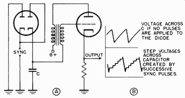
Figure 25. Pulse counting circuit.
The transient voltage frequency is set by tuning the cathode stabilizing circuit to one and one half times the desired oscillator frequency. This voltage component added to the grid characteristic insures synchronization of the blocking oscillator to the desired driving pulse despite variations in tube characteristics, power supply voltages, and the amplitude of the driving pulses.
The third type of circuit used for frequency division is known as a "pulse-counting" circuit, and is shown in Figure 25a. Two diodes replace the grid leak resistor of the conventional blocking oscillator. As successive driving pulses are applied to the diodes, the capacitor C charges in steps, each step corresponding to another pulse. Figure 25b. Finally, the last step has sufficient amplitude to trigger the oscillator. Thus, for several incoming pulses, only one pulse is produced by the oscillator.
The frequency division from 31.5 khz to 60 cycles is usually done in four stages in the ratios of 3, 5, 5, and 7. A complete chain of frequency divider circuits, consisting of four stabilized blocking oscillators is shown in Figure 26. Note that the stabilizing tuned circuit is put in the grid of the blocking oscillator to illustrate another version of this type of dividing circuit.
4-19 The Pulse Shaping Circuits. The timing pulses which are generated in the frequency divider chain do not have the correct wave form required for the composite synchronizing signal.
105001. 2100 1. 420 %
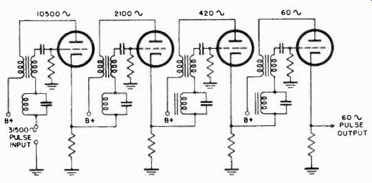
Figure 26. Frequency divider chain.
They are merely used to "key in", at the correct time, the horizontal, vertical, and equalizing pulses which are generated in the shaping circuits. The horizontal and vertical blanking pulses also are formed in the shaping circuits. The blanking pulses must be integrated with the synchronizing pulses to form the standard FCC signal shown in Figure 19.
4-20 The Equalizing Pulses. The equalizing pulses are half as wide as the horizontal sync pulses and are spaced at half-line intervals. Six equalizing pulses occur before the vertical sync signal and six occur after it during each complete field.
Although only twelve equalizing pulses are needed per field, it is simpler to generate a continuous train of them and turn them on only when they are needed. If the equalizing pulses were to occur throughout the field, they would have a frequency of 31.5 khz (twice that of the horizontal pulses which occur 15,750 times per second). 31.5 khz is also the frequency of the master oscillator. Therefore, the master oscillator frequency can be used to key the equalizing pulse shaper.
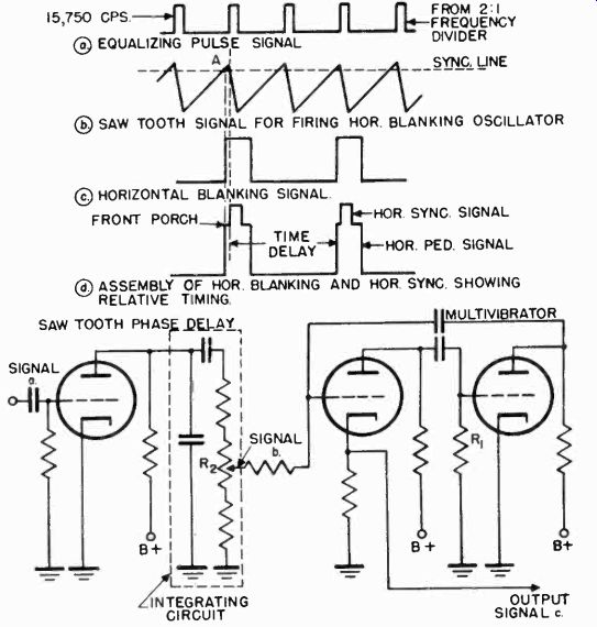
Figure 27 Generation of horizontal blanking pulses.
The multivibrator makes an ideal pulse shaper because it generates square wave pulses. The pulse width of the multi vibrator can be adjusted by setting R3 in Figure 21. This control can be used to set the width of the equalizing pulses, after which R2 can be set for exact synchronization with the master oscillator signal which is fed into the grid of the first stage.
4-21 The Horizontal Blanking Pulses. The horizontal blanking pulses cut off the television picture in the receiver during the time that the spot is returning from the right to the left side of the screen. The blanking signal also provides a "pedestal" on which the horizontal sync pulse is superimposed. The frequency of the blanking pulse is equal to the horizontal scanning rate, which is 15.75 khz. In other words, for each horizontal sync pulse there is one blanking pulse.
The horizontal blanking pulse precedes the horizontal sync pulse by a very short time interval as shown in Figure 27d. This time interval is often called the "front porch". The front porch may be considered a safety factor to simplify the separation of the sync pulses from the blanking signals at the receiver. Under weak signal conditions, the start of the sync and blanking pulses would not be distinguishable if the pulses were to occur close together.
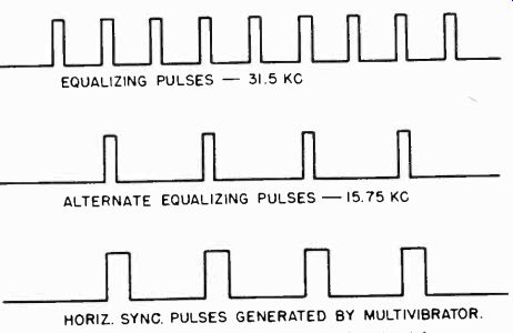
Figure 28. Relative phase of equalizing and horizontal sync pulses.
Since the horizontal sync pulse must occur in phase with the equalizing pulse as shown in Figure 27a and d, means must be provided for keying the blanking pulse shaper circuit a short time interval before the sync pulse occurs. A method for accomplishing this is shown in Figure 27. The equalizing pulses are fed to a 2:1 frequency divider which produces pulses occurring at 15.75 khz. These pulses are then coupled to an integrating circuit which changes their shape to a sawtooth, as shown in Figure 27b. If a point on this sawtooth voltage such as A, is used to trigger the blanking pulse shaper circuit, the blanking pulse will occur a short time before the equalizing and horizontal sync pulses. A multivibrator is used as the blanking pulse shaper. The pulse width is determined by R-1 and the "front porch" interval is set by the adjustment of the voltage divider R-2. R-2 determines the point on the rising sawtooth at which the multivibrator will trigger.
4-22 The Horizontal Synchronizing Pulse. Horizontal sync pulses occur 15,750 times per second, which is half the frequency of the equalizing pulses. The 2:1 frequency divider which was used to obtain a keying signal for the blanking pulse shaper also feeds a signal to the horizontal pulse shaper. The relative phases of the equalizing and horizontal sync pulses are shown in Figure 28. In the top figure are the equalizing pulses occurring at 31.5 khz. The 2:1 divider circuit produces alternate equalizing pulses occurring at 15.75 khz. These key another multivibrator whose output pulse width is set for the wider sync pulses shown in the bottom of the figure.
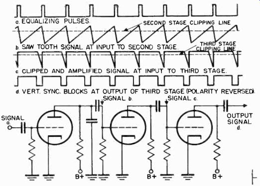
Figure 29. Formation of the vertical sync signal.
4-23 The Vertical Synchronizing Signal. The vertical sync signal is made up of a series of six wide pulses. The vertical sync signal is serrated, or divided into these six smaller pulses, so as not to interrupt the regularly timed firing of the horizontal scanning system during the transmission of the vertical sync signal. The serrated vertical sync signal is formed by integrating the equalizing pulses to form a sawtooth voltage as shown in Figure 29. The sawtooth signal is then clipped in two successive amplifier stages to produce the desired wave form.
4-24 The Vertical Blanking Signal. The vertical blanking signal performs a function similar to that of the horizontal blanking pulse. It is often referred to as the vertical pedestal signal.
It blanks out the scanning beam during the time that the beam is retracing from the bottom to the top of the picture. The vertical blanking signal is a wide pulse occurring once each field or 60 times per second. A multivibrator, synchronized by the 60 cycle timing signal from the last frequency divider stage, is used to generate the pulse.
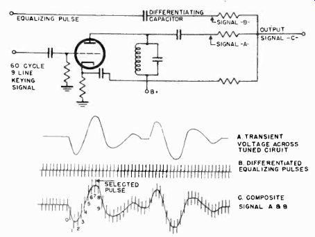
Figure 30. Forming the 60-cycle, three-line keying signal.
4-25 Combining the Sync and Blanking Signals. Two 60 cycle keying signals are required in order to combine the various pulses produced in the shaper circuits. One keying signal interrupts the train of horizontal sync pulses for a time interval corresponding to nine horizontal sync pulses. During this interval, a group of eighteen equalizing pulses is inserted. The other 60 cycle keying signal adds six serrated vertical sync pulses to the six center equalizing pulses (of the eighteen inserted between the horizontal sync pulses). The first of the 60 cycle keying signals is the signal obtained from the last frequency divider. It is called a 60 cycle, 9-line keying signal, because it interrupts the horizontal sync pulses for a period of nine lines. The other keying signal is called a 60 cycle 3-line keying signal because it interrupts the equalizing signal for a period of six pulses (corresponding to three lines). The timing of the leading edge of the 60 cycle 3-line keying signal is very critical and must be accurate within a time interval corresponding to the width of an equalizing pulse. This timing accuracy can be obtained by firing the 60 cycle 3-line signal from the leading edge of a particular equalizing pulse. It is difficult, however, to make certain that synchronization occurs on the correct equalizing pulse out of the 525 which are generated during each 60 cycle period.
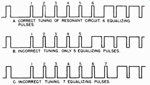
Figure 31. Effect of circuit tuning on composite synchronizing signal.
The method by which the 60 cycle 3-line keying signal is correctly synchronized may be understood by referring to Figure 30. The equalizing pulses are fed to the plate through a differentiating circuit. The differentiated equalizing pulses appear as in Figure 30b. At the same time the 60 cycle 9-line keying signal is fed to the grid. This keying signal shock excites the tuned circuit in the plate and causes transient oscillations as shown in the waveform of Figure 30a. The transient oscillations and the differentiated pulses are combined in the plate circuit. If the resonant circuit is correctly tuned, the 7th equalizing pulse which occurs after the 60 cycle 9-line keying pulse will appear at the top of the transient and becomes the 60 cycle 3-line keying signal. Correct tuning of the resonant circuit enables just 6 equalizing pulses to be keyed in later, as shown in Figure 31a.
If the circuit is incorrectly tuned so that an equalizing pulse other than the 7th is at the top of the transient, an incorrect number of equalizing pulses will appear in the final signal as shown in Figure 31b and c.
4-26 Insertion of the Equalizing Pulse into the Horizontal Sync Signal. The horizontal sync pulses are interrupted for an interval of nine lines. This is accomplished by feeding the horizontal sync pulses into a modulator stage (tube D) as shown in
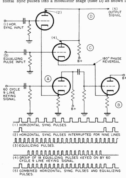

Figure 32. Circuit used to insert equalizing pulses into horizontal sync
pulses.
Figure 32. The 60 cycle 9-line keying signal is fed into tube A. The keying signal from tube A is fed to the cathode of tube D and cuts it off for nine horizontal lines. At the same time the equalizing pulses are fed into another modulator, tube C. The 60 cycle 9-line keying signal is fed into the cathode of tube C, 180° out of phase with the signal that is injected into the cathode of tube D. This causes tube C to conduct for a period corresponding to 18 equalizing pulses. The plates of the two modulators, C and D, are tied together to form the combined horizontal and equalizing pulse signal.
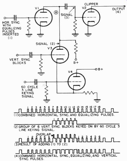

Figure 33. Circuit used to mix serrated vertical sync pulses with combined
horizontal and equalizing pulses.
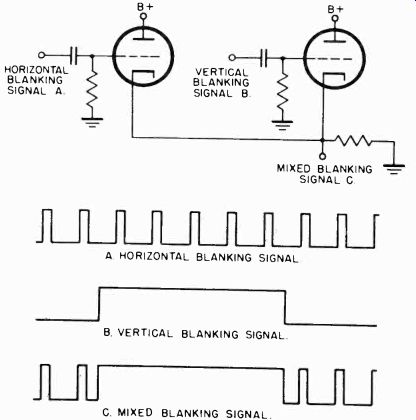
Figure 34. Circuit used to mix horizontal and vertical blanking signals.
4-27 Inserting The Vertical Sync Pulse. The 60 cycle 3-line keying signal is used to select the six vertical sync blocks. It is fed into the grid of tube V4 (Figure 33) whose cathode is tied to the cathode of V3. This puts the keying signal on V3 and causes it to conduct for a period equal to six vertical sync blocks.
Therefore, even though a continuous chain of vertical sync blocks are fed to the grid of V3, only six blocks appear at the plate of V3 as shown in waveform 2.
The serrated vertical sync signal consisting of the six blocks is then combined with the horizontal sync and equalizing pulses.
The horizontal sync and equalizing pulses which were previously combined are fed to the grid of V1. These are shown as waveform 1 in Figure 33. At point A, where the modulator tubes V1 and V3 are tied together, a combined signal such as shown in waveform 3 of Figure 33 results. The signal is the combination of waveforms 1 and 2. The equalizing pulses which overlap the vertical serrated pulses are clipped off by tube V2, giving the complete synchronizing signal shown in waveform 4 of Figure 33.
4-28 Mixing the Horizontal and Vertical Blanking Signals. The horizontal blanking signal, Figure 34, is modulated by the vertical blanking signal so as to blank it off during the vertical retrace interval. This is accomplished simply by tying the cathodes of the modulator tubes together as shown in the figure, and results in the waveform shown in Figure 34c. The combined blanking signals and sync signals are mixed later in the video mixing amplifiers.
MONITORS
4-29 Picture Monitors. The picture monitor is essentially a television receiver without a radio frequency section. Picture monitors are located at various points in the television station to check the quality of the image.
The sweep circuits of a studio picture monitor, which is used to check the pictures on more than one camera, are synchronized by driving pulses fed directly from the sync generator. In this way, there is no interruption of the scanning while switching the monitor from one camera signal to another. Other types of picture monitors receive both the synchronizing and picture signals together in order that they may provide adequate monitoring of the over-all signals before they are sent to the transmitter. Still other monitors are equipped with shading controls when used with iconoscope cameras.
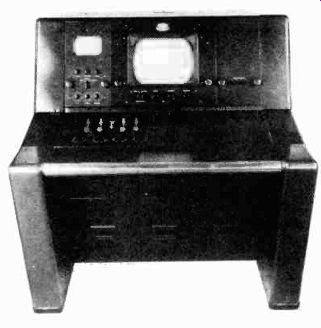
Figure 35. Picture monitor. (courtesy DuMont)
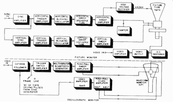
Figure 36. Block diagram of picture and oscillograph monitor.
Monitors use tubes of 5, 7, 10, 12, and 15 inch diameter. The small tubes are convenient for monitors used with portable remote pick-up equipment. The larger monitor tubes are preferable in studio control equipment. They make viewing more comfortable for the video engineer and the program director who must observe the camera picture while directing the program. The larger monitors are also used in the master control equipment, the film camera chains, and in the transmitter room.
The picture monitor (Figure 35), used in the studio control room for checking the camera signal, is the most complete monitor found in the station. Its functions are threefold:
1. It contains a picture tube with video and sweep circuits to monitor the outgoing picture signal.
2. It contains a small three or five inch waveform monitor which allows observation of either the input or output video signal. This monitor may be considered a cathode-ray oscillograph whose sweep is fixed at either of two frequencies: half the horizontal frequency or half the vertical frequency. This permits the viewing of two lines or two fields.
3. Four of the controls of the image-orthicon camera are located in the monitor. These are the beam current, the beam focus, the target voltage and the photocathode focus controls.
These controls determine the power supply voltages applied to the camera tube. They are located in the picture monitor because the voltages applied to the camera tube can be most accurately set while observing their effect on the picture.
A block diagram of the picture monitor section is shown in Figure 36. The circuits used are much the same as those found in the 5 inch monitor used as a camera viewfinder.
4-30 Video Waveform Monitor. The video waveform monitor, located in the control room monitor, permits examination of the camera output signal at either the vertical or horizontal frequency. The video waveform monitor is a cathode-ray oscillograph whose sweep frequencies are set at either 30 cycles or 7,875 cycles.
The sweep for the waveform monitor is generated by a multivibrator. The multivibrator is triggered by either 30 cycle vertical or 7,875 cycle horizontal pulses, received from the sync generator. Either frequency is selected by the sweep frequency switch. These pulses are amplified by a trigger amplifier before being applied to the multivibrator. Another section of the sweep frequency switch changes the time constant of the charging circuit in the multivibrator for horizontal and vertical operation. Sawtooth voltages of either line or frame frequency are thereby produced in the plate circuit. Two lines or two fields can thus be observed on the waveform monitor.
The video amplifier of the waveform monitor consists of a 6AK5 amplifier followed by a push-pull stage using two 6AG7s.
MIXING AND DISTRIBUTION AMPLIFIER
4-31
The mixing and distribution amplifier combines the video signal from the camera with the blanking and composite sync signals from the synchronizing generator. Provision is usually made in this unit to distribute the combined signal to several outputs, each of which is isolated from the other. The mixing and distribution amplifier is also used as a distribution amplifier if the video and synchronizing signals from a single source must be fed to several outlets.
4-32 Mixing the Video and Sync Signals. A block diagram of the circuit used for combining the video and sync signals is shown in Figure 37. The video signal from the camera is fed through a co-axial line to the video gain control. The camera signal is amplified in a two-stage video amplifier (tubes V28-301 and V28-302), having a gain of approximately 15. The signal is then fed to the grid of V28-305, which is the mixer stage. Simultaneously, blanking pulses are fed into V28-306 and amplified to a 5 volt peak-to-peak level. These blanking pulses are then applied to the suppressor grid of mixer tube V28-305. The video and blanking signals applied to the grid and suppressor of the mixer, respectively, appear as in Figure 38a and b. In the common plate load of V28-305, the video and blanking signals are mixed and appear as in Figure 38c. A 1N34 crystal rectifier follows the mixing tube to clip any portion of the blanking signal which rises above a d-c level determined by the crystal bias control R-1. This fixes the blanking (or black) level in the video signal.
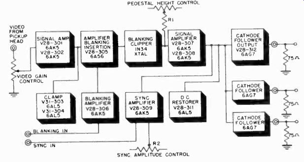
Figure 37. Block diagram of mixing and distribution amplifier.
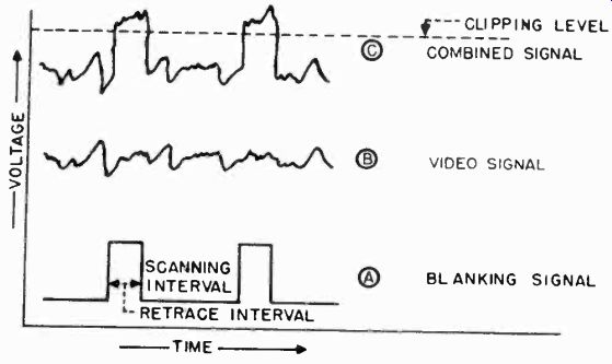
Figure 38. How blanking signal is combined with video signal.
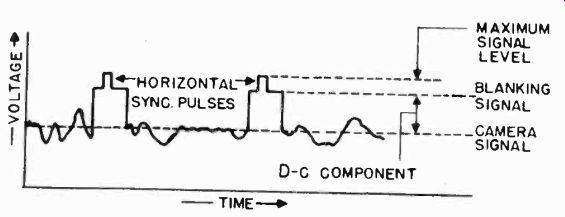
Figure 39. The completed composite video signal.
The signal which now contains blanking pulses is amplified by V28-307 and V28-308 in parallel. The parallel combination is used to provide sufficient voltage swing at the plates without having to drive the grids over a range great enough to cause appreciable non-linearity.
Sync signals at a 1 volt level enter the monitor control from the synchronizing generator and are applied to the grid of V28-309. The plate load of V28-309 is common to V28-307 and V28-3-8. Mixing is therefore effected across this common plate load. The combined signal at this point appears as in Figure 39. The sync level is controlled by variation of the grid bias resistor R-2 on V28-309. To meet the requirements of the standard video signal, the sync is adjusted to equal 25% of the peak-to-peak amplitude of the composite signal.
The combined video signal is coupled to the outgoing transmission line through a cathode-follower V28-312. V28-311 is a d-c restorer on the grid of V28-312 which reinserts the d-c level lost in coupling the video signal through the a-c amplifiers.
By paralleling several cathode-followers in the output, several isolated output points are obtained.
THE VIDEO TRANSMITTER
4-33
The video or picture transmitter generates an amplitude modulated signal and operates on a carrier frequency in the television band between 50 and 216 megacycles. There are twelve television channels in this band of frequencies, each six megacycles wide. In the 6 Mhz channel both picture information and sound information must be transmitted. The picture signals occupy 4.25 megacycles of this channel, while the sound signals use only 25 kilocycles.
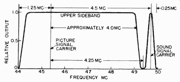
Figure 40. Single sideband television signal.
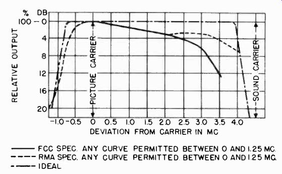
Figure 41. RMA and FCC specified transmission channels.
4-34 Sideband Suppression. In normal double side band transmission, as used in standard broadcasting, the modulating frequencies appear above and below the carrier frequency. If double side band transmission for television were used, an 8.5 Mhz band would be required, since the video signal contains frequencies from about 30 cycles to 4.25 megacycles. To limit the width of the television signal sufficiently so that it will fit into the assigned channel, a special modulating method is used. This method is known as vestigial sideband transmission. In this system only a portion of the lower side band of the picture information is transmitted as shown in Figure 40. The picture carrier is placed 1.25 Mhz above the lower edge of the assigned 6 Mhz channel. The entire upper sideband of picture information is transmitted in the 4.25 megacycle region above the picture carrier. The sound carrier is located 4.5 megacycles from the picture carrier. This leaves a frequency band of 0.25 megacycles between the picture and sound signals. The last quarter megacycle is used as a guard band between the sound carrier and the picture signals in the next channel.
In the 1.25 megacycle region below the picture carrier it is possible to attenuate or reduce the lower side band energy substantially to zero by the time the lower edge of the 6 Mhz channel is reached. Some types of transmitters accomplish this attenuation of the lower side band by tuning out these frequencies in the radio frequency amplifier stages. Other forms of transmitters pass the carrier frequency with the double side band modulation signals up to the final power amplifier stage. A filter for attenuating the lower sideband frequencies is then inserted in the transmission line between the final amplifier stage and the antenna. Whichever method is used, the video trans miner should have a frequency response characteristic represented by the ideal curve shown in Figure 41. Also shown are the practical standards for the response characteristic of a video transmitter as proposed by the FCC and RMA.
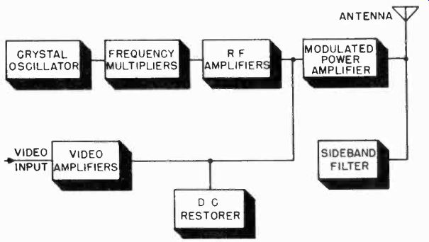
Figure 42. Block diagram of high level modulated transmitter.
4-35 Modulation Methods. There are three basic sections of the television transmitter, namely (1) the radio frequency generator, (2) the modulator, and (3) the power amplifiers. Two methods of modulation are used. One method is high-level modulation used in the television transmitter shown in the block diagram of Figure 42. In this system, the radio frequency is generated at a lower frequency than the carrier, and then multiplied to obtain the carrier frequency. The RF carrier is then amplified in a series of RF amplifier stages, sharply tuned to the carrier frequency. Simultaneously, the video signal from the studio is successively increased in several video amplifier stages, until a signal level, sufficient to modulate the final amplifier, is reached. The undesired portion of the lower sideband is removed by a high-level filter in the antenna circuit. This system is called high-level modulation because the RF carrier is modulated in the last high power amplifier stage.
In the low level modulated transmitter (Figure 43), the stages which generate the radio frequency carrier are similar to those used in the high-level type. At the output of the frequency multiplier stages, the carrier level is only a few watts. Video modulation takes place at this point. The modulated RF carrier is then amplified by a series of wideband stages. The pass band of each stage is so tuned that the unwanted portion of the vestigial sideband is removed.
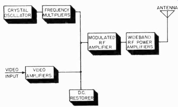
Figure 43. Block diagram of low level modulated transmitter.
Both high level and low level modulation are used in commercial transmitters. Each system has advantages and limitations.
The wide band video amplifiers capable of supplying a video signal of large amplitude and high power for high level modulation are costly and inefficient. Tubes capable of delivering the modulation power have relatively high interelectrode capacitances and waste much of the energy at the video frequencies.
On the other hand, since a large number of wide band RF amplifiers are needed in low level modulation systems, great care must be exercised to keep the transmitter tuned so that the band-pass characteristic is adequate for satisfactory picture resolution. In high level modulation, the picture quality is affected only by the response of the video amplifiers which remain stable over long periods. Only one final RF power amplifier stage and the vestigial filter need be tuned with high level modulation. In low level modulation, misadjustment of any of the wide-band RF amplifiers seriously affects the picture quality, and may even reinsert the unwanted portion of the vestigial sideband.
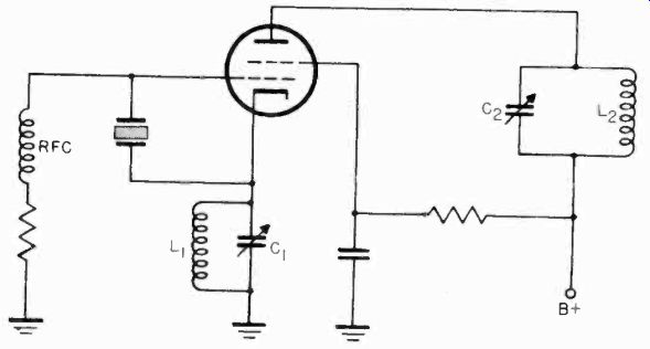
Figure 44. Tri-tet oscillator.
It is apparent from the foregoing discussion that the three important considerations concerning the design of video transmitters are the video power required for modulation, the tuning of the RF power amplifier, and the use of either a vestigial sideband filter or vestigial sideband tuned amplifiers.
4-36 Generation of the Carrier Frequency. The principal problem encountered in generating the carrier frequency is that of maintaining the required frequency stability. The frequency stability is specified by the FCC as being plus or minus 0.002% of the assigned carrier frequency. A temperature controlled low frequency crystal is usually employed in order to assure this stability. Since it is difficult to grind quarts crystals which will be stable at frequencies above 10 Mhz, it is standard practice to start with a crystal frequency of about 5 Mhz and use a series of frequency multiplier stages to reach the desired carrier frequency.
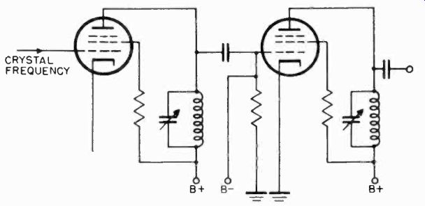
Figure 45. Simplified schematic of frequency multiplying stages.
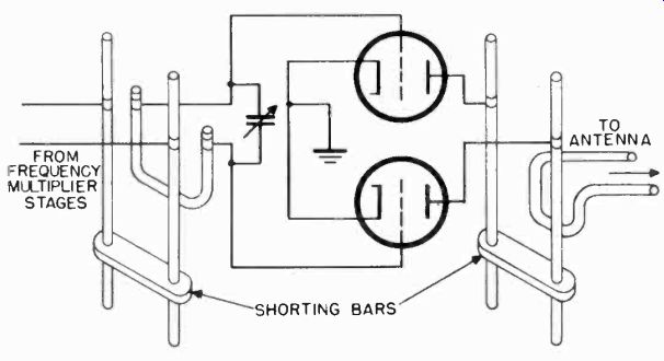
Figure 46. Transmission line tuned push-pull RF amplifier stage.
4-37 Tri-Tet Oscillator Circuit. The tri-tet oscillator is commonly employed in television transmitters and is shown in basic form in Figure 44. A quartz crystal is used between the control grid and the cathode of the tube. Tuned circuits are employed in the plate and cathode. When the tuned circuit L1-C1 is tuned to a considerably higher frequency than that of the crystal, oscillations take place. These oscillations occur at the resonant frequency of the crystal. They also. cause variations in the control grid potential, causing the RF signal to appear in amplified form in the plate circuit. The plate resonant circuit L2-C2 may be tuned to the fundamental (crystal) frequency or to a multiple of that frequency.
4-38 Multiplier Stages. The frequency multiplier stages are conventional class "C" amplifiers in the low level stages. A typical two stage frequency multiplier is shown in Figure 45.
The tank circuit in the plate is tuned to twice or triple the incoming frequency on the grid, depending upon the degree of multiplication desired. In the multiplier stages, the tuned circuits are made up of conventional capacitors and inductors. The frequency multiplying stages are generally of the pentode type since they are more efficient for this purpose. In high-level modulation transmitters, the desired carrier frequency is generally obtained in the stage preceding the final power output amplifier, which acts as anon-multiplying stage. The required RF power is gradually built up in the multiplying stages.
4-39 High Level Modulation of Power Amplifier. In a high level modulation transmitter only the final power amplifier is modulated by the video signal. Figure 46 shows a typical power amplifier. The tuned circuits used in this final stage are generally made up of transmission line conductors rather than conventional capacitors and inductors. The distributed capacitance and inductance of the transmission lines are tuned by cutting the lines to the proper length, determined by the carrier frequency. The push-pull arrangement is used with triode tubes to simplify the problem of neutralization. Small air condensers for neutralizing are built into the transmission lines.
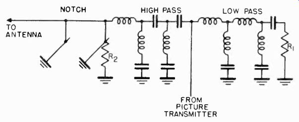
Figure 47. Vestigial sideband filter.
The grid circuit of the final power amplifier is tuned to the frequency of the RF carrier. The video modulator is also coupled into the grid and modulates the carrier frequency. The modulation of the carrier by the 4.5 Mhz video signal produces side bands extending for 4.5 Mhz above and below the carrier frequency. The plate circuit of the final stage must be broad-band tuned for the carrier and the sidebands which are generated.
The amplified wideband signal is coupled from the plate circuit to the antenna.
4-40 Vestigial Sideband Filter. The vestigial sideband filter is a permanently tuned RF filter which is inserted into the output circuit of the final power amplifier of a high-level modulated transmitter. The filter removes a portion of the lower sideband of the modulated carrier and passes on to the antenna a signal which occupies a bandwidth of less than 6 megacycles.
A schematic diagram of the vestigial sideband filter is shown in Figure 47. It consists of three filter sections. A low-pass filter absorbs the undesired energy in the lower sideband and dissipates it in resistor R1. The desired signals are then passed through a high pass filter. A notch filter is located between the antenna and high pass filter. The notch filter is tuned so that the load resistor R2 dissipates all energy at a frequency which is 0.25 megacycles below the lower limit of the channel.
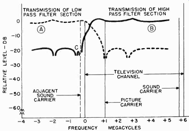
Figure 48. Transmission characteristics of vestigial sideband filter.
The effects of the three filters on the transmission characteristic of the system is shown in Figure 48. Curve A is the transmission characteristic of the low pass filter. The frequencies below the picture carrier are readily passed by this filter. These frequencies are then dissipated in the resistor R1. The high pass filter is tuned to accept the frequencies above the picture carrier (curve B) and pass them on to the antenna.
The notching filter absorbs energy at the adjacent sound carrier frequency (point C) and dissipates it in resistor R2. The purpose of the notching filter is to eliminate all possible interference with the adjacent sound channel.
4-41 Low Level Modulation R-F Amplifiers. The RF amplifiers used with the low level modulation system must meet a number of special requirements. Instead of being tuned to a single resonant frequency, as they are with high level modulation, each stage must have a wide band response and linear output between the limits of modulation. In addition to this, suppression of the lower sideband must take place in the RF amplifiers.
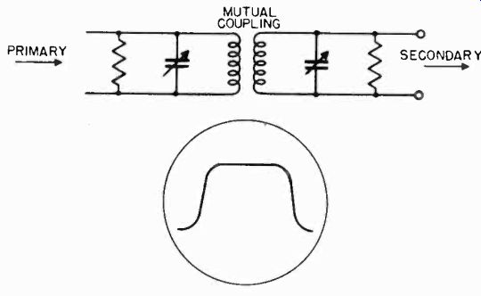
Figure 49. Overcoupled circuit and its response characteristic.
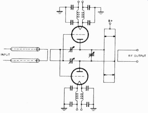
Figure 50. Wideband RF amplifier circuit.
Adequate bandwidth for the video signals about 4 Mhz is attained through the use of overcoupled circuits. The response characteristic of an overcoupled circuit is shown in Figure 49.
Figure 50 shows the circuit arrangement of a wide band amplifier as used in RF power stages. Tuned transmission lines are employed in the grid and plate circuits. The coupling and loading may be varied in order to produce a wideband response characteristic.
Variation in coupling is accomplished by changing the physical position of the secondary with respect to the primary. This is usually done by means of a worm drive gear system. Figure 51 shows the physical arrangement of the RF power tubes and transmission line elements. On the right is the gear drive which changes the coupling between the tuned lines.
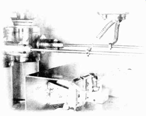
Figure 51. Worm drive mechanism for changing coupling in RF amplifier.
The wideband RF amplifier stages are tuned so that the upper sideband of the television information is included in the passband characteristic of the tuned circuits. The carrier is positioned on the edge of the low frequency end of the passband and the circuits are adjusted to give a smooth frequency response characteristic over the 4 Mhz upper sideband. This adjustment produces a single sideband transmission system, since the tuned circuits reject the lower sideband. The tuned circuit in each amplifier stage contributes to the overall attenuation of the unwanted frequencies.
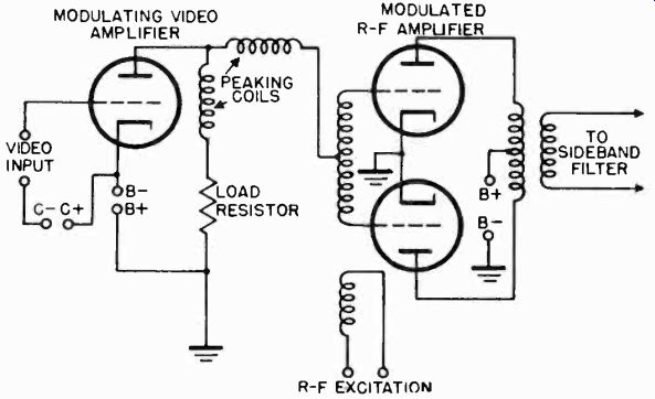
Figure 52. Modulated Class n amplifier.
4-42 Modulators. The modulator section of the transmitter
consists of several stages of video amplification, a sync expander, and a circuit for reinserting the d-c component which is lost in the capacitive coupling between amplifiers. In high level modulated transmitters, about 600 volts of peak-to-peak video signal is required to modulate the grid of the final power amplifier stage. 150 volts or less is necessary to properly modulate a transmitter using the low level system.
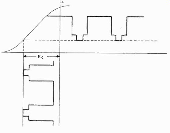
Figure 53. Grid characteristic of Class B modulated amplifier.
All video amplifier stages must have a frequency response of 30 khz to above 4 megacycles. Standard practice is to feed 1 volt of video signal from the studio to the video amplifiers. The required video gain then depends on the power level at which modulation takes place.
4-43 Modulating the R-F Signal. When the video signal has been increased to the voltage level required, it is coupled to the RF carrier through the grid of the modulated stage. Fundamentally, the modulator stage is a class "B" amplifier, as shown in Figure 52. The tube is biased in the vicinity of cutoff.
Figure 53 shows the ideal case where the grid bias is adjusted so that the signal excursions on tl3e grid maintain the output waveform over the linear portion of the grid plate transfer characteristic. Should the bias be excessive, operation will take place on the lower knee of the curve, and the resulting non linearity will cause compression in that part of the signal which represents the white picture area. When the bias is not as great as the tube linearity will permit, sync compression may take place. Sync compression is the result of operation on the upper knee of the transfer characteristic, and when present the sync level will occupy less than 25% of the composite video signal.
The video signal amplitude at the modulator stage is of prime importance since upon this factor depends the modulation percentage level of the television carrier. The FCC standards state that the sync pulses must occupy 25% of the total RF signal amplitude, and that the transmitter be modulated to at least 15% of the peak level of a white picture. These modulation limits are shown in Figure 54 for a black picture with a white line. In order to operate within these prescribed limits, which permit an effective modulation capability of only 85%, it is necessary to drive the transmitter with a greater sync-to-picture ratio.
Analysis of the proportions of Figure 54 shows that the input video signal must consist of 29.5% sync with respect to the peak to-peak video signal. A sync stretcher, such as described elsewhere in this section is incorporated in the circuit between the video amplifier and modulator to expand the sync and compensate for the loss in sync-pulse amplitude in the succeeding modulator and power amplifier stages.
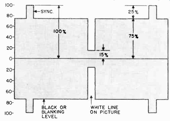
Figure 54. Modulation limits of transmitter.
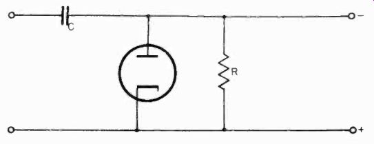
Figure 55. Circuit of diode d-c restoration circuit.
4-44 D-C Restoration. The d-c component of the video signal which represents the average brightness of the televised scene is lost when the signal is passed through the video amplifier stages to the modulator stage. The d-c level of a television signal can be reinserted by using a d-c restoration circuit, such as shown in Figure 55. By making the RC time constant of the circuit much greater that the time interval of one line of the television picture, a voltage is built up across the diode load resistor which is about equal to the peak value of the video signal (the level of the tips of the sync signal). This voltage is applied to the grid of the modulator as an additional biasing potential. As shown in Figure 56, the effect of the d-c restorer is to refer the tips of the sync signals to the same level. Without d-c reinsertion, the video signal would center itself about the bias level and the sync tips would assume different levels.
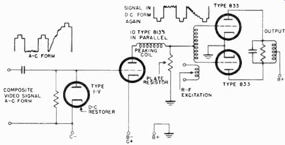
Figure 56. D-C re-insertion in grid circuit of video modulator

Figure 57. Modulated television carrier.
The d-c restorer brings all the sync pulses to the same bias level at the grid of the modulator. The tips of the sync pulses thus serve as a reference level for the black and white portions of the video this point on in the transmitter. The modulator is therefore direct coupled to the grid of the RF power amplifier. Once the RF signal has been modulated by the video signal with the d-c level properly restored, the sync and blanking levels remain fixed. Any variation in the modulation envelop, caused by the video signal, will correspond to changes in the d-c background brightness of the picture (Figure 57).
In addition to restoring the d-c signal, the d-c restorer, by holding the sync tips at a fixed level, maintains the modulated RF signal at a constant peak power level.
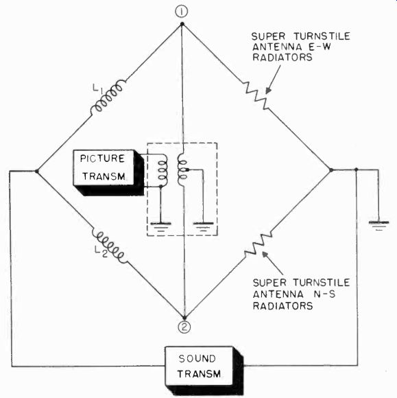
Figure 58. Circuit of diplexer.
4-45 Coupling the Transmitter to the Antenna. It is common practice to use the same antenna for both the picture and sound transmitters. If both of these signals are fed directly to the antenna, sound signals would enter the picture circuits of the transmitter, and the picture signal into the sound circuits.
Cross-coupling of the signals is prevented by using a network known as a "diplexer". The diplexer has two reactors which form two arms of a bridge circuit. Figure 58. The other two arms of the bridge are formed by the elements of the antenna radiators. The picture transmitter is push-pull coupled to points 1 and 2 of the bridge. The impedance of L-1 is made equal to L-2. The impedances of the elements of the radiators are also equal. The bridge is therefore in balance and the potential at point 1 equals the potential at point 2. Since the picture transmitter feeds two points of equal potential with respect to the sound transmitter, no sound signal can feed back into the picture circuits.
The sound transmitter is fed into the circuit across the mid-points of the antenna and the inductances L-1 and L-2. Since the potentials at paints 1 and 2 are equal, no picture signal can pass into the sound circuits. Thus, while the signals from the two transmitters are fed simultaneously to the same antenna, the output circuits are effectively isolated from each other. A view of the transmission lines elements (L-1 and L-2) of a diplexer is shown in Figure 59.
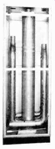
Figure 59. Interior of diplexer. (courtesy RCA)
THE SOUND EQUIPMENT
4-46 The sound equipment used in a television station is very similar to that used in a broadcasting station, and therefore will only be treated briefly here.
The sound pick-up equipment consists of microphones, phonograph turntables, and motion picture film soundtrack recorders.
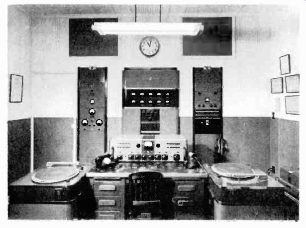
Figure 60. Sound control unit. (courtesy RCA) Generally, the phonograph equipment
is located in the studio control room where the program director and the technical
operators coordinate the recorded sound with the television pickup. Additional
transcription turntables are located in the master control room for use when
inserting background music into those programs where close synchronization
is not required between the audio and the video. The sound track equipment
used to reproduce audio signals recorded on film are also located in the master
control room. Figure 60 shows a sound control unit with station announcement
microphone and pick-up turntables located in the master control room.
4-47 Handling Sound Equipment. The sound pick-up equipment used on the studio floor requires special handling, since it is important that the microphones do not appear in the picture.
The microphone is generally mounted on a long boom (Figure 61) and adjusted so as to be over the heads of the actors out of range of the camera. A number of microphones connected to amplifiers, adjusted for different gains can be coordinated with the perspective of the pick-up cameras to produce realistic sight and sound combinations. For example, when a switch is made from a close-up camera to a distant camera, a corresponding change in the sound level and quality must occur simultaneously with the change in cameras. Suitable frequency response filters are incorporated in the amplifier circuits to give the impression of a shift in distance from the scene.
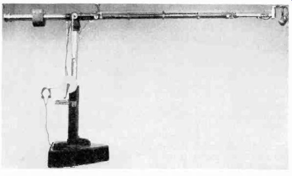
Figure 61. Microphone boom. (courtesy DuMont)
4-48 Microphones. Three types of microphones are used with the "mike" boom in the studio and on remote pickups. These are called uni-directional, bi-directional, and non-directional, The uni-directional microphone is sensitive only to sound coming from a single direction. The speaker must talk into the sensitive side of the microphone. Any noise or voices coming from other directions are greatly attenuated. The bi-directional microphone has equal sensitivity at the front and back, but attenuates sounds coming from the sides. Two people can conveniently talk into one microphone of this type. The non-directional microphone is equally sensitive to sound from all directions.
The microphone converts sound energy into electrical signals.
The electrical output from the microphone is fed to the sound control desk inside the control room. Each microphone is connected to a separate amplifier whose gain and frequency response can be controlled by the audio engineer. Since several microphones may be used in the studio, the engineer must maintain a volume balance between them by adjusting the gain of each amplifier. On the sound control board, the engineer has a series of switches by means of which he may turn on any combination of microphones and blend their outputs. He may also switch in the sound from phonograph of film pick-ups.
After the sound signal has been properly adjusted at the monitor desk, it is sent, via a separate line, to the audio transmitter.
4-49 The Sound Transmitter. The carrier frequency of the sound transmitter is 4.5 megacycles higher than the video frequency carrier. The sound accompanying television pictures is transmitted by frequency modulation.
The maximum frequency deviation permitted by the allocation for television sound is plus or minus 25 khz as compared to plus or minus 75 khz for standard FM broadcasting. The frequency deviation of the television sound is purposely limited to 25 khz to allow as much room as possible in the 6 megacycle television channel for the video signals. The fidelity of the television sound signal is as good as that of the standard FM signal, even though its frequency deviation is less. The frequency deviation is determined only by the loudness of the audio signal at the transmitter and not its frequency response.
The lineup of sections of the FM transmitter differs considerably from those in the AM transmitter. A block diagram of an FM transmitter is shown in Figure 62. The heart of the FM system is the reactance tube. This tube converts the audio signal coming from the studio into a frequency modulated signal.
The reactance tube and its circuits are connected across the tank coil of an oscillator (such as a Hartley or Colpitts). If no audio signal is fed to the reactance tube, the oscillator generates its carrier frequency. When a signal of varying frequency and amplitude is applied to the grid of the reactance tube, variations in the reactance tube plate current occur. The plate current also flows through the oscillator tank circuit. The reactance tube circuit is so designed that the changing plate current effectively changes the value of inductance or capacity across the oscillator tank circuit. As this reactance changes with variations in the audio signal, the oscillator frequency continuously varies above and below the carrier frequency. The stronger the audio signal, the greater is the frequency deviation. The rapidity with which the signal deviates from the carrier frequency is determined by the frequency of the audio signal. High frequency sounds cause the frequency modulated signals to vary more rapidly.
The mean or carrier frequency of the oscillator is not the final carrier frequency of the transmitter, nor are the frequency deviations at this point in the transmitter as high as the allowable 25 khz. For example, the mean frequency of the oscillator ...
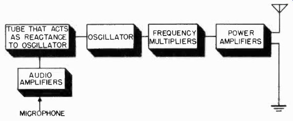
Figure 62. Block diagram of FM sound transmitter.
... may be only 2 Mhz. At this point in the circuit the volume of the audio signal may be controlled so that the 2 Mhz carrier deviates plus or minus 5 khz. If this signal is fed into a frequency doubler stage, the carrier frequency will be 4 Mhz and the frequency deviation 10 khz. Successive frequency multiplier stages bring the carrier frequency up to the desired sound carrier with a frequency deviation of 25 khz.
Except for the reactance tube circuit which converts the audio signal into a frequency modulated signal, the components of the FM transmitter are the same as those described for the video transmitter. The frequency multiplying stages and the power amplifiers are similar in the sound and picture transmitters.
MASTER CONTROL
4-50 A simple television station system was shown in Figure 1. It consisted of a single camera and associated control equipment which fed the signal to the transmitter. Large-scale television station operation requires a far more complex arrangement of equipment than shown in this simple system. To handle a full day of programming, more than one studio is required, each equipped with several cameras. A great deal of television program material comes from movie film, so that provision must be made for extra film cameras. Other programs are televised remotely and transmitted to a control room at the station before being put on the air. Many stations use network programs to fill some of their broadcast time. The integration of all of these facilities requires a central monitoring point through which programs pass before transmission. This centrally located point in the television station is called the master control room. The complexity of the master control depends upon the number of studios, film cameras, and remote facilities which the station has available.
A typical small television station installation is shown in Figure 63. Here three studios A, B, and C, are available, two for live talent operations, and a third for film pick-up. Shown in dotted lines are two remote program sources, typically used for sports pickup and similar field activities. Also indicated is a source and output for network programs. Finally, the output to the transmitter is shown.
The master control shown in Figure 63 must accept signals from as many as six sources and furnish signals to either the transmitter, the network outlet, or both. While all of these facilities will seldom be in use at one time, situations will arise when all of the master control equipment is necessary. The control room must be designed to meet such an emergency.
An example of how all the station facilities shown in Figure 63 could be used simultaneously is as follows. A live talent program could originate in Studio A, which would require the output of Studio C (the film studio) for portions of the program.
An advertiser could be viewing the rehearsal of a new program, scheduled for subsequent use, emanating from Studio B. Remote source 1 could be feeding a sports event to the network.
The rehearsal of a new remote program could also be in progress, requiring transmission of signals from remote pickup 2 to master control for distribution to viewing rooms, where the possibilities of the program can be evaluated.
It is easy to see that the master control room which is adequate to cope with such a typical situation will call for a relatively large complement of complex equipment. A listing of the functions that such a master control room must perform gives some idea of the type and amount of equipment necessary.
4-51 Master Control Functions. The following is a list of functions that must be performed by master control.
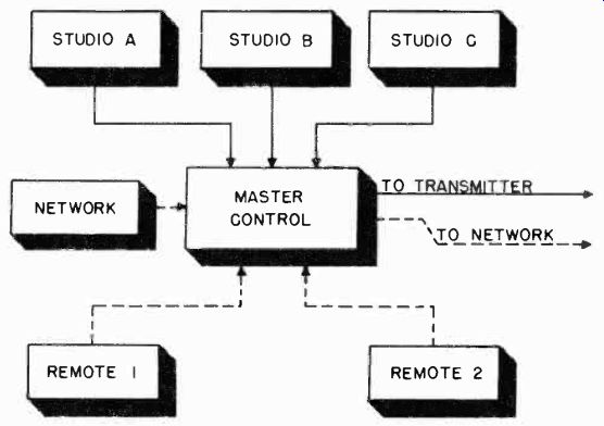
Figure 63. Block diagram of facilities of a small television station.
1. From the synchronizing generator, usually located in the master control room, driving and blanking pulses must be fed to all local studios.
2. Picture signals derived from local studios must have synchronizing information added to them at master control before they are fed to a network or to the transmitter. Remote and incoming network programs which are furnished complete with synchronizing information must pass through master control without any additional synchronizing information being added.
However, if the incoming sync signal is distorted, provision must be made to "clean it up".
3. Provision for phasing the synchronizing generator pulses to suit the needs of film projectors must be included.
4. When remote or network programs are contemplated, the vertical synchronizing information from these remote sources must be properly related in phase and frequency to those of the local synchronizing generator, so that switching from local to remote and from remote to local generators may be accomplished without affecting receivers tuned to the station.
5. Facilities for the monitoring and selecting of the proper video channel must be incorporated so that the transmitter or network outlet may be given the required program at the correct signal level and at the proper time. In other words, master control must have a picture monitor for each source of signal. If, for example, the program on the air combines signals from two sources (say, live talent and film), a picture coming from each source must appear on a separate monitor at master control.
At the cue of the director, the master control operator can switch one or the other picture on the air.
6. Selecting and monitoring facilities must also be available for the "preview" signal, which is the next signal to be placed on t)le air.
7. Monitoring and terminal facilities must be available for the servicing of incoming and outgoing network programs.
8. To facilitate the setting up of the foregoing three functions, video patch panels are necessary so that the several program sources may be properly routed through monitoring facilities to the transmitter, as well as directed to viewing rooms and executive offices.