In the previous section we looked at a basic tubes (valves) oscillator circuit. It is possible to use this as a simple radio transmitter. If an aerial were to be connected to the top of the coil Li and an earth to its bottom end, the oscillations produced would be radiated as electromagnetic waves, but not very effectively because the power would be low. However, high frequency amplifying stages can be used to build up the strength of the oscillations, culminating in a power output stage capable of putting out anything from a few watts to hundreds of thousands of watts into the air.
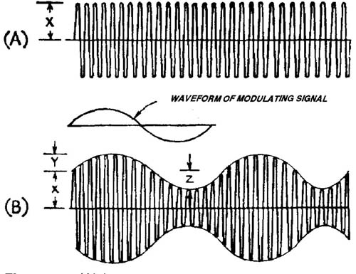
FIG. 1 (A) Unmodulated continuous or carrier wave showing constant amplitude.
(B) Carrier wave after modulation has been imposed on it in the form of a sine
wave (middle diagram). Note amplitude varying in concert with the sine wave.
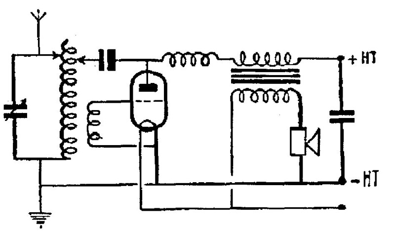
FIG. 2
What would be sent out from such a transmitter would be a continuous series of magnetic waves which by itself does not contain any information in the way of speech or music but which is able to carry such sounds if they are imposed upon it. For this reason it is known as a carrier wave. The process of imposing speech and music on it is called modulation and the end result is known as a modulated carrier wave. The modulation system used for broadcasting in the long, medium and short wave bands is called amplitude modulation, discovered as long ago as 1913 and still unchanged in principle. The term means exactly what it says: the amplitude of the continuous waves is modulated — altered in size — by the speech, or music. One of the best-known methods of achieving this is called anode modulation, which works on the basis of varying the HT applied to the anode of the oscillator in unison with the variations in sound picked up by microphone. A simple circuit capable of achieving this is shown in FIG. 2, in which you will see that the secondary of an LF trans former has been inserted in the feed from the HT battery to the HF choke. The microphone shown in the primary circuit of the transformer is a carbon type, which needs to be supplied with an energizing voltage, in this case obtained from the LT supply for the tube (valve) heater. Sounds reaching the microphone are converted into fluctuating DC currents which, flowing through the transformer primary, induce voltages in the secondary which either aid or oppose the steady DC voltage from the HT battery, thus causing the anode voltage on the tube (valve) to rise and fall in sympathy. This in turn alters the amplitude of the oscillations generated by the triode. The amount by which their amplitude is affected by the modulating device is called depth of modulation. This has to be set carefully, as too little would result in the transmissions having background noise, whilst too much would cause distortion of the sounds. The simple transmitter shown here would certainly work to a certain extent but not very well because the depth of modulation would not be very great. This could be much improved by introducing another triode as an amplifier for the microphone, as shown in FIG. 3. It will be seen that the anode of the amplifier tubes (valves) is connected to the HT feed to the oscillator and also to an LF choke inserted in the lead to the HT supply. As we have seen in the previous section, the anode current of the amplifier will rise and fall with the variations in sound at the microphone, thus altering the voltage drop across the choke and imposing a good depth of modulation on the oscillator. Just as the strength of the latter can be built up by amplifiers, so can the power of the former, the aim always being to match them correctly. Anode modulation, as it is called, was for a long time the principle method used, but others, such as grid modulation, have joined it. Whatever the means of modulation the end result is the same and if a 1913 speech transmitter could be found and made to work it could be received on a modern AM receiver. It is this continuity of basic principles that gives vintage radio a unique advantage over other hobbies: no matter how old the set, it can still be made to give out speech and music.
Sidebands
As well as modulating the amplitude of the carrier wave, the sounds picked up by the microphone have another effect, of causing it to ‘spread out’ on either side of the basic frequency of oscillation. If we accept that the range of human hearing is from about 20 Hz up to l6kHz, to reproduce them all properly they would have to be imposed on the carrier wave. Supposing that this were 1000 kHz, what are called sidebands of 16 kHz would be setup on either side consisting of 1000 kHz — l6kHz and 1000 kHz + 16 kHz, that is from 984 kHz to 1016 kHz. Thus the total ‘airspace’ taken up by the transmitter would 32 kHz. This would be fine if there were but a few transmitters on the air but in real life there are hundreds on the medium wave band alone. This band, covering as it does from 550 kHz to 1600 kHz, has a total usable ‘space’ of 1005 kHz, which could accommodate only 31 stations. The situation would be even worse on long waves where the total space is only about 150 kHz and fewer than five stations could be squeezed in. In practice radio stations are separated by no more than 9 kHz so the sidebands must be limited to no more than 4.5 kHz. This places a severe limitation on the range of musical frequencies that may be broadcast, but the tolerance of the human ear is such that the end result at radio receivers is reasonably acceptable, especially where speech and modern ‘non-music’ are concerned.
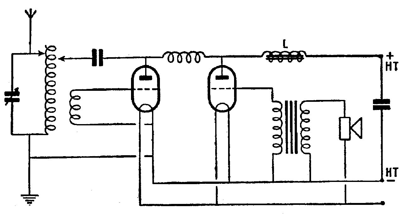
FIG. 3
We shall look again at sidebands shortly when discussing the way in which they affect the design of radio receivers.
Receiver principles
We saw in Section 5 how the combination of a coil and a variable capacitor makes it possible to select any particular frequency from the hundreds arriving at an aerial system. If this chosen frequency is fed to the anode of a diode it will pass only the positive half-cycles, so closely spaced in radio transmission that the result at the cathode will be a steady DC voltage plus varying audio frequencies mimicking exactly those used to modulate the transmitter. In simple receivers the carrier wave has no further use and will be discarded, whilst the AF signals may be fed directly to a pair of earphones or to an amplifier.
The good points of a diode as a detector are that it will accept large inputs without overloading and its output is free from distortion. However, its sensitivity is low and it imposes a loading effect on the preceding tuned circuit which impairs it selectivity.
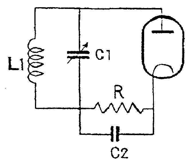
FIG. 4 The circuit of a simple diode detector L1 and C1 are respectively
the tuning coil and the tuning capacitor. R is the diode load resistor, on
which the AF output from the diode is developed. C2 is a by-pass capacitor
which filters out the remaining RF.
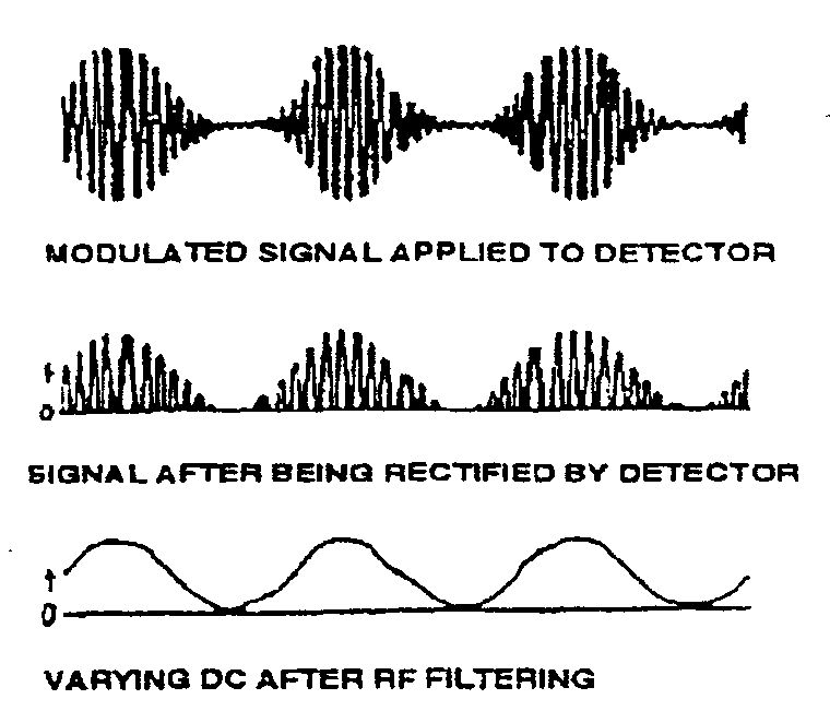
FIG. 5
The amplifier following a diode may be a triode. However, it is possible to make the latter act as both detector and amplifier by taking the incoming signal to its grid via a small capacitor. The grid then acts as the anode of a virtual diode consisting of itself and the filament (or cathode). In this case the steady DC resulting from the carrier is built up across the capacitor, with the filament positive and the grid negative, the AF signal also imposed :on the grid. If the negative voltage were allowed to build up indefinitely it would reach a level where it would ‘cut off’ the anode current, so a resistor is connected between grid and filament or cathode through which the voltage can leak away — hence the term ‘grid leak’. Its values may be from about 1 mf up to 5 mf and it may be connected either directly between grid and filament or indirectly by shunting it across the grid capacitor. The AF signals on the grid modulate the electron stream as usual and result in a varying anode current carrying the information which may be reproduced in earphones or passed on by resistance capacity or transformer coupling to another amplifier and ultimately to an output stage and a loudspeaker.
A triode used in the way just described is called a grid leak detector or merely a grid detector in the USA (an upmarket term ‘cumulative grid detector’ may be encountered now and again but it never really caught on because it was too much of a mouthful). Due to the virtual diode effect loading is still imposed on the tuned circuit and although the sensitivity is reasonably good the selectivity is poor. To overcome this problem, reaction (regeneration in the USA) was introduced. It was found that if a certain proportion of the output signal at the anode is fed back to the grid, much as in an oscillator circuit, the load on the tuned circuit is reduced, resulting in greatly enhanced selectivity and sensitivity. The trick is to have the amount of feedback adjusted to just below the point at which oscillation would occur, otherwise the triode would behave as a low power transmitter capable of causing severe interference to neighboring receivers. In the early days of broadcasting carelessly adjusted reaction and oscillating detectors were a major menace and the old British Broad casting Company and the radio press carried on a constant publicity campaign to persuade listeners to avoid offending in this way.
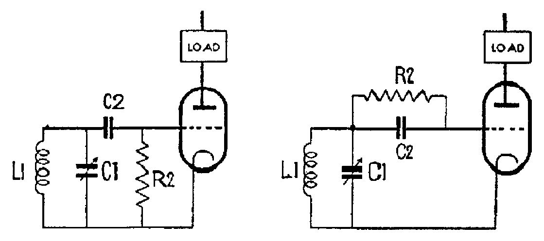
FIG. 6 Two versions of grid leak detection.
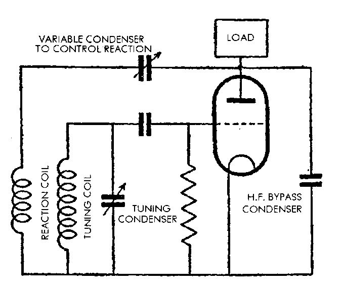
FIG. 7 Adding reaction to a grid leak detector L2. The ‘reaction coil’ is
wound on the same former as L1 and induces positive feedback into it. C2, the
‘reaction capacitor’ enables the degree of feedback to be adjusted. C3 by-passes
any residual RF to the earth line.
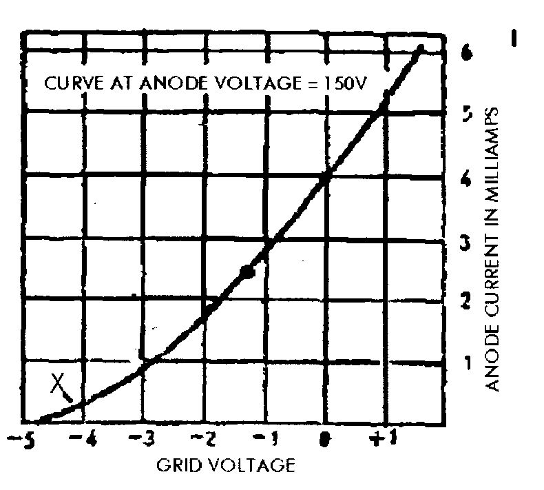
FIG. 8
An alternative way to use a triode for detection is to make use of its characteristic curve. Cast your mind back to the way in which an amplifier is operated at the centre of the straight part of the curve (Y) in order that both positive and negative portions of the AF signals may be reproduced equally. Now consider what will happen if the grid bias is adjusted to reduce the anode current to near the cut-off point (X). Only the positive going part of an incoming signal will have any effect now since it will make the grid less negative and cause anode current to flow; on the other hand the negative going signal will only increase the negative bias and maintain the cut-off condition. If an RF signal from a tuned circuit is applied to the grid the result will be a varying positive voltage derived from the original AF modulation which will then be reproduced as amplified AF signals at the anode. Because of its use of the bend in the characteristic curve this effect is known as anode-bend detection (simply anode detection in the USA).
The anode-bend detector imposes little loss on the tuned circuit and good selectivity is obtainable without the need for reaction. However, the incoming signal does have to be fairly strong to make it work properly and for this reason it was seldom employed without an RF amplifying stage preceding it.
Before leaving the subject of detectors we should look at the simplest of all, and one that was used in thousands of receivers through the 1920s and even later. This is the so-called crystal detector which was usually composed of a small chunk of lead sulphide, otherwise known as galena. This has the useful property of permitting electricity to travel through it in one direction only, just like a tube (valve) diode. In practice the crystal would be held in a small metal cup, above which was mounted a small movable arm holding a tiny spring-like coil of wire called the ‘cat’s-whisker’. Randomly disposed on the surface of the crystal are ‘sensitive spots’; the trick is to adjust the cat’s-whisker to make contact with one of these, at which point diode action is obtained. An aerial and an earth are taken to a simple tuning device which is connected to one side of the detector and a pair of headphones is connected to the other. When a good signal is received from a transmitter, and the cat’s-whisker is adjusted properly, enough rectified signal passes through the headphones to enable them to repro duce the original AE The only optional refinement is a small capacitor shunted across the headphones to remove any residual HF, so the complete receiver consists of no more than four or five components. No batteries are required, hence the attraction of the crystal set to listeners on low incomes.
With the principles of reception now established we can look in the next section at some typical early designs for receivers.
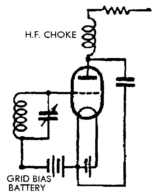
FIG. 9 Basic anode-bend detector circuit.
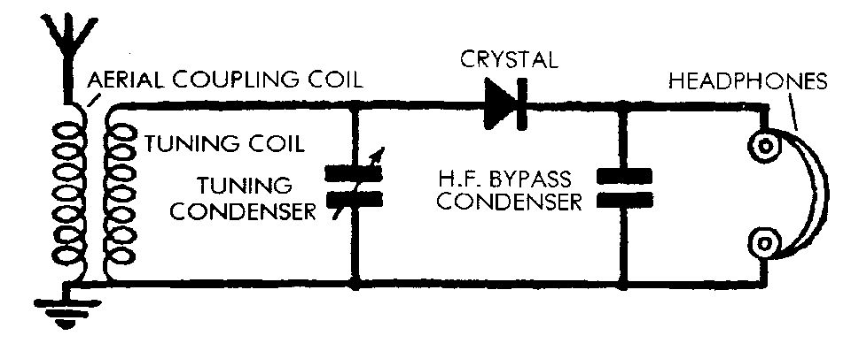
FIG. 11
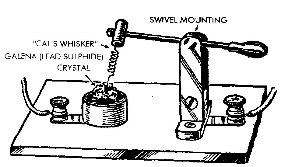
FIG. 10