This round-up of connection techniques concludes that British-designed Hierarchical Interconnection Technology could be the basis of the next generation of PCB interconnect
by JOHN CURRY
The semiconductor revolution which has transformed equipment design and construction methods over the past 25 years has in turn has brought about a revolution in connection techniques.
Methods of connecting components to PCBs, daughter boards to mother boards, mother boards to backplane boards, have all been streamlined to minimize costs and maximize equipment production, performance and reliability. Similar changes have taken place in cabling and interconnecting equipment.
Another factor that has helped transform connectors and connection techniques is the massive rise in price of traditional connector materials such as tin, brass, copper and gold.
Most connector pins and sockets have there fore been redesigned to reduce the amount of material needed to produce them and cut production time and costs wherever possible.
For example, most commercial connector pins are now pressed from metal sheet and folded, instead of being machined from solid metal, the pressing technique providing savings in material and allowing mass production at lower cost.
Costs have been further reduced by techniques such as selective plating of pins and sockets, and reducing gold and other plating thicknesses to a minimum.
The connector revolution has also been helped by the various industry recessions.
These have made all sectors of the industry very cost conscious, and resulted in ever increasing demands for cost-effectiveness in equipment design, production testing and installation.
The need for greater cost-effectiveness has been complemented by what has become an obligatory requirement for shorter product development and manufacturing times brought about by increased use of computer aids. Manufacturers have to get their new products to the market as soon as possible to secure sufficient market share to cover high development costs. Thus productivity is a key requirement in all modern connection systems.
SOLDERLESS TECHNIQUES
All these factors have resulted in faster, cheaper and easier to use methods of connection and a massive swing to solderless techniques. In telecommunications, for example, the need to minimize operating costs has obliged organizations like British Telecom to adopt quicker and cheaper ways of making connections in telephone system installations.
As a result, time-consuming terminations such as solder- and screw-terminal connections have largely been superseded by simpler and much faster solderless techniques such as insulation-displacement connection, which require the minimum of tools, little or no preparation of the wires to be connected, and therefore little skill.
An everyday example is the now familiar white telephone plugs and sockets used in home and offices. These use a non-solder technique called cable-piercing which enables them to be wired with a single squeeze of a special crimping tool. The squeezing action causes the connecting contacts of the plug or socket to pierce the cable's outer insulation and make contact with the copper wire inside.
INSULATION DISPLACEMENT
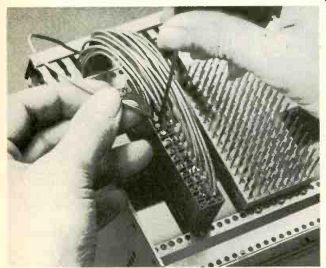
Another widely-used solderless wiring technique is insulation displacement connection, a good example of which is the Rapid Wiring System that inserts and connects a wire in a single push action without the need for wire-stripping.
Designed for wiring prototype or small production run PCBs by hand, or high density wiring of boards by machine, it utilizes a one-piece beryllium copper contact which push fits into a PCB and has an IDC terminal at one end, and an IC-pin at socket the other.
==========
2 to 24-pole PCB connectors
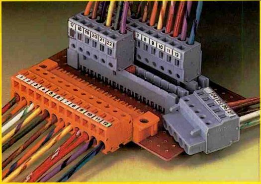
A range of PCB connectors comes from Hellermann Electronic Components. These are available in 2 to 24-pole and with a pitch of 5mm and 5.08mm. The female connector with cage-clamp connection is for solid, stranded and flexible conductors from 0.14mm2 up to 2.5 mm2, (AWG 26 to 14). Male connectors are available with straight or angled solder pins 1 by 1 mm or 1.2 by 1.2mm. There is a test socket for test plugs 2mm and 2.3mm dia. Pole marking can either be with adhesive marker strips or direct printing. The female connectors can be operated from above as well as parallel to the conductors. The front entry system allows the connection or disconnection of conductors when the connector is mated. The male connectors are suitable for PCBs up to a thickness of 3.5mm. They can be screwed to the board with the aid of fixing elements to ensure that optimum guidance of the female connector is obtained. Depending on the mounting conditions, there are several possibilities for having the connectors mated in a non-reversible way.
Screened D-connector
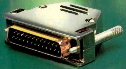
A modified version of the Ceep subminiature D-connector hood has been designed to minimize r.f.i. and EMI and to offer continuous screening in conjunction with the cable braid. Metallized plastic construction reduces the cost and weight while remaining effective.
D.i.l. PCB connector with IDC
Du Pont Connector Systems has introduced an entirely new dual-in-line solder-to-board, and male pluggable, connector system. This is based on new IDC technology and is suitable for high performance, high reliability applications in harsh environments, such as those encountered in the telecommunications industry.
Du Pont's "Quickie" d.i.l. PCB connector has a patented IDC contact with an integral anchor, which provides base-to-cover locking and ensures correct positioning of the conductor in the IDC area. It also features a pre-loaded, bridge-type cover, with dual-sided cable entry, which makes it ideal for automated assembly operations and for daisy chain applications. Low profile strain-relief is available as an optional extra.
The new connector is supplied in grid sizes of 2.54 by 2.54mm, 2.54 by 7.62mm and 2.54 by 15.24mm, and with 4 to 64 contact positions. The male pluggable version has selective gold-plated contacts: the solder-to-board version has tin/lead-plate contacts.
==========
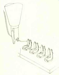
The wire is simply pushed into the slot created by the contact's two tines. The width of the slot is slightly narrower than the wire's conductor. Thus as the wire is pushed down, the two tines cut its insulation and firmly grip its conductor, making a secure gas-tight connection.
The single-push wiring action is three times faster than wirewrap and enables terminals to be daisy-chained with a common link, further reducing the number of wires that need to be cut. In addition, the IDC tines are one third the height of comparable wirewrap posts, yet can accommodate three 30s.w.g. wires, and can be re-used up to 50 times without impairing the integrity of the gas-tight connections they provide.
The savings in time and space which IDC connections provide, coupled with their reliability and re-usability, has prompted BT, and telecommunications utilities world wide, to adopt these connectors as the standard method of connection for tele phone wires and cables. BT is currently in the process of a massive conversion project which will result in their use in all UK telephone exchange and installation wiring.
The telecommunications industry's re cognition of its integrity as a dependable means of connection has helped spread the use of the technique to cables, including flat cable and coaxial cable. As a result, there are now IDC versions of most cable connectors.
PRESS-FIT CONNECTORS
Solderless connectors are also superseding soldered edge-connectors on printed-circuit boards in low- and medium volume applications. Called press-fit connectors, they have tapered pins which are simply pressed into an appropriate pattern of plated-through holes on the PCB This compresses and forces their outer surfaces against the plating so that they conform to the shape of the holes, rather than vice versa, resulting in connections that are gastight, resilient and both electrically and mechanically sound.
The board requires no heat treatment.
Thus the technique limits internal stresses and PCB warpage. In addition, the pins can be readily replaced. It also enables a variety of terminations to be fitted, including plugs, sockets, and wiring posts such the RWS IDC terminal.
For example, the widely used DIN41612 Eurocard connector is available with press-fit pins. Called "compliant" pins, they have a tapered c-shape cross section. Press fit connectors with a variety of other tapered-pin cross section shapes are also produced.
==============
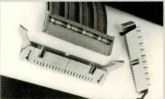
New latch for IDC
What are claimed to be the only IDC connectors in the world to offer both vertical latch and eject facilities are now available from Nortronic Associates. The top latching offers the option of considerable savings in PCB area compared with equivalent side latch connectors. Both straight and right-angled versions are available and both of these styles are now stocked in 10 to 50-way DIN configurations. Each IDC component has its pins fully protected and is centrally polarized as a guarantee against incorrect insertion. Insulation material comprises glass-reinforced thermo-plastic carrying a 94V0 rating, while each of the phosphor-bronze contacts has a gold plating over nickel. Current rating is 1A. A full range of mating female sockets is also available.
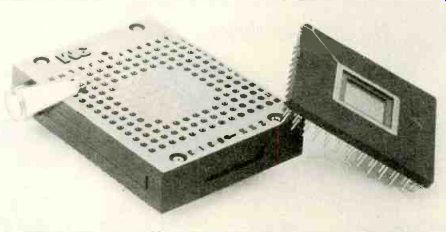
Pin grid array sockets
A family of Textool zero insertion pressure (zip) test and burn-in sockets from BFI Electronics will pack tightly onto any PCB surface and will handle a variety of P.G.A. (Pin Grid Array) devices. They will therefore be useful to quality assurance, test and programming departments.
The zero insertion pressure feature of these sockets protects expensive P.G.A. devices from damage during insertion and withdrawal. The package is securely locked into place by lowering a level-operated cam. The sockets are designed to provide maximum use of board space. The cam level is positioned on the side of the socket, making the sockets end-to-end stackable. Optical locating holes on the sockets permit robotic loading and unloading, and because the lever remains above the edge of the socket when locked, manual unloading is easier. Seven matrix sizes, ranging from 10 by 10 to 21 by 21, are available. The pin pattern can be customized for any specific device on an average 7-day turn-around.
Handtool for IDCs
An IDC connector hand termination gun designed to provide the speed of assembly associated with IDC but at price level normally realised by crimping tools is now available from Dage Eurosem.
The gun, manufactured by Robinson Nugent, has been designed so that certain elements of the connector assembly task, such as wire stripping and crimping, are no longer necessary. As a result the gun can complete twice as many terminations compared with traditional crimping tools during the same period. The hand gun, suited for the assembly of connectors used in computer, instrumentation and test and measurement applications, is capable of making typically 800 terminations an hour. The hand tool's ratcheting mechanism allows handle release only after the wire is seated correctly in the contact and also means that, if required, the connector can be reversed. A self-indexing system automatically positions the connector for wire insertion which speeds the assembly process. However, the tool can be manually indexed if required. The stuffer blade is adjustable to allow termination of 20 to 30 a.w.g. wire with different insulation thicknesses. A range of metallized plastic or plastic hoods are available as required.
=================
GTH CONNECTORS
Another popular solderless connector technology is the gas-tight high-pressure contact (g.t.h.) developed by Burndy which, as its name suggests, uses a contact-pressurizing arrangement to make a positive gas-tight connection.
Connection is made by simply lifting the connector's outer body, inserting a pre-stripped wire into low insertion force g.t.h. socket, and then pushing the body down to its normal position. This forces the contact against the wire, and penetrates any oxidized deposits on the mating surfaces.
A key feature of the system is that it uses relatively inexpensive contact materials such as tin-plated phosphor bronze.
Burndy has applied the g.t.h. technique to a variety of different connection requirements including IC sockets, connectors for flat cables, connectors for terminating wires on PCBs, and connectors for closely stacking PCBs.
ZERO INSERTION FORCE SOCKETS
Another increasingly popular method of providing plug-in mountings for dip components on p.c.b's is the zero insertion force socket.
As its name implies, the zif socket enables dip devices to be fitted or removed without the need for any insertion or withdrawal force. Nor are any tools required. The socket's contacts are normally open, and are closed by a cam-action lever arm.
On being closed, the contacts grip the smooth flat sides of the dip device's legs, the last 15° of cam movement providing a sliding action that wipes the legs clean to ensure a positive contact.
Most zif sockets are press-fit devices with wire-wrap or similar pins, and therefore eliminate the need for board preparation.
HEIRARCHICAL INTER-CONNECTION TECHNOLOGY
Custom chips, v.l.s.i., hybrid circuits and surface-mount techniques collectively en able equipment designers to pack so much functionality and therefore complexity onto a PCB, that the value of printed circuit boards will rise significantly.
Double Eurocards for example can currently cost up to about £ (x1.34 for $) 1500, but the increased complexity possible is likely to result in boards of this size containing functionality worth £ (x1.34 for $) 50,000, i.e., over 30 times more valuable. Moreover their complexity would be so great that they will take several hours to test.
Thus there is a strong case for partitioning such designs into a number of small 'daughter' modules which plug onto a Eurocard, to simplify production and maintenance. A possible answer to this problem is a British-developed technique called Hierarchical Interconnection Technology (hit).
Hit is based on the use of 'daughter' modules whose profile is less than that of a DIN41612 connector, i.e. under 12mm. Up to eight can be mounted on one side of a double Eurocard. Single and double-sided designs in various sizes and substrates are being evaluated. They will fit into zif-type rectangular sockets having 130-140 contacts.
An IEE working group has been set up to prepare a proposal for a new equipment practice on Hit. Thus Hierarchical Interconnection Technology could be the basis of next generation of PCB interconnect.
--John Curry is managing director of Astra lux Dynamics Ltd.
===========
160 Way High-density DIN connector
A new design of DIN connector which meets the increasing demand for higher densities in interconnections is manufactured by Erni and distributed by Radiatron Components. The connector is fitted with five rows of 32 contacts, making 160 ways in total. Contacts are rated at 4A at 20°C ambient and are spaced on a 0.1 by 0.1 in. matrix. Male connectors have right angle p.c.b, solder terminals: female connectors are offered with a choice of solder spills, wire wrap tails or compliant press fit terminations. Erni has also designed a special moulding which fits between two E160's on a double eurocard. This accepts up to nine of the special high current, co-axial or fiber-optic inserts already offered for the DIN 41612 M connections. This is part of a whole range of DIN 41612 connectors which include connectors for surface mounting and versions fitted with press-fit right angled spills.
IBM PC-AT dual card slot connector
Viking Connectors (UK) Ltd has introduced a dual card slot, 18 + 31 position connector as part of their new low cost card-edge connector series. This new connector has been specifically designed for the motherboard i/o slots in the IBM PC AT computer or compatible products. The one-piece design replaces the need for two separate connectors. thus saving connector and production costs. Others of the Viking range of card-edge connectors include those suitable for all IBM PCs.
Backplane for industrial control
A press-fit backplane system for use in industrial control applications is announced by EMB Ltd. The board is flexible enough to form the heart of a wide range of complex multi-processor systems. Being DEC-compatible, it will be of interest in many industrial automation applications. The hack planes are typically multi-layer boards using universal bus configurations and termination networks suitable for address and data lines.
The design is based on DEC interface standards, with vertical headers for I/O. It is implemented using Press-fit solderless connectors.
Microwave connectors
Norbain Technology Ltd has launched a range of high-reliability semi-rigid and flexible microwave cable assemblies designed for use in commercial communications and avionics applications. Designated the Seatlex 2 and manufactured by Sealectro, the cable assemblies are available in a variety of connector types including SMA, TNC and N types in either plug, right angle plug, bulkhead jack D hole and bulkhead jack 4 hole flange versions.
All microwave cable assemblies provide consistent microwave performance to 18GHz enabling low v.s.w.r. to he specified without spikes present in the upper frequency spectrum. In addition, they can he used up to 26GHz with minimal degradation using SMA connectors. All assemblies are 100°/6 tested with each individual assembly supplied with v.s.w.r. test plots. The microwave cable assemblies are available ex-stock in half meter and one meter lengths in 0.125 in. 0.18 in and 0.250 in standard cable sizes. Non-standard assemblies will be made to order.
Surface-mount interconnection
Snap (sustained necessary applied pressure) is the name given by Dowty to their inter-board connection system. This uses an extruded flat conductor cable with a polyester coating which has gaps to expose the pre-tinned copper conductors at intervals. A simple tool is used to cut the cable and from the contact points in one easy operation. The Snap connector clamp provides uniform pressure across the connector strip. The tinned conductor tracks on the PCB match the spacing of the connector cable and no soldering is required. The system requires two holes to be drilled in the PCB (of different sizes for polarity). The connector requires little space on the hoard and is less than 13mm high. is gas-tight and vibration resistant.
PLCC sockets
A new range of competitively-priced, rugged Textool plastic-leaded-chip carrier sockets offering ease of alignment and extraction of Jedec C packages is now available from Microbusiness, Newbury. The design of these production sockets allows visual and mechanical polarization of both the device into the socket and the socket to the circuit board to ensure positive alignment and electrical integrity. Slotted corners provided greater ease of device extraction with a simple hand tool. In addition, the socket offer 0.025in test access probe holes for each contact; 0.020 in stand-offs for cleaning and ventilation holes for solvent removal; and sturdy solder tails with radiused ends for easy installation.
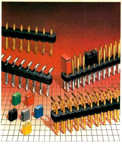
Headers and links for PCBs
The Winslow range of un-shrouded headers are available in single and dual rows with straight contacts or at 90 degr. They can have any number of contacts up to 72. Two thousand standard products cater for different pin lengths: but anything not in the catalogue can he made to order.
Shorting links have open or closed tops and six colors. They offer a low-cost alternative to DIL switches. Terminals can be tin or gold-plated.
------------
Also see: Designing a surface mount connector
==========
(adapted from: Wireless World , Jan. 1987)