New 34-way s.m.c. incorporates key market features.
by ADRIAN HYNER
Anew surface-mount connector idea is aimed at meeting the need for an s.m.c. that can interface with existing component and substrate technologies but will offer the most critical benefit s.m.t can bring, namely savings in board and system space.
The majority of s.m.c. designs have been modifications of standard connector systems and as such suffer from severe disadvantages. These include too high a profile and they can suffer from structural failures resulting from a lack of sufficient mounting stability to cope with high insertion and removal forces.
Among the major features to bear in mind when developing a new purpose-designed low-profile s.m.c. is that, for the moment, the receptacle tails must terminate on one side of the PCB Because surface-mounted components are not yet available in sufficient variety and at the right price to make wholly-s.m.t. designs a viable solution for many applications, most s.m.t.-based PCBs currently feature a mixed-technology approach, in which both s.m.t. and p.t.h. components appear on the same board and are all soldered on one side of the board. A further limitation is presented by the fact that cable pitch of 0.005in is the current industry standard, restricting the PCB header interface to that pitch.
Admittedly these are temporary restrictions. There is no doubt the next step will be to have the surface-mount connector on both sides of the PCB because of the density advantages that can be accrued by terminating on two sides. Amphenol is already producing 0.0025 in IDC cable and the first products in a connector range to terminate it, with a view to producing an s.m.c. on 0.0025 in pitch in due course. Nevertheless, for the interim period when these restrictions do apply, a connector solution must be considered.
=============
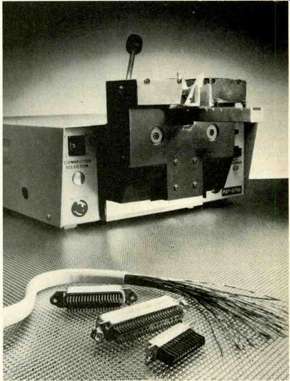
Machine speeds IDC connectors
Latest in a line of semi-automatic connector assembly machines from Amphenol is the microprocessor-based Electro-Pierce Mark V. Its production rate is 30 to 40 connectors per hour.
The machine is programmable for the entire range of connector sizes, from 14 to 64 way, the different connector sizes being accommodated by simple adjustment of a nest fixture. It can be programmed to skip selected positions. This skip function program is learned by the machine from a known-good connector and is retained until the machine is switched off.
Wires are selected by the operator, one pair at a time, and are positioned to activate the drive motor. The machine automatically cuts the wire to length and inserts it into the contacts, and then positions for the next pair. Optional accessories include an adaptor kit for top entry and rack and panel connectors, and a cable clamp closer for 157 Series connectors with cable clamp and plastic hood.
=============
A further requirement from a low-profile s.m.c. is that the receptacle should exhibit various mounting capabilities so that the connector can be either glued, solder tab bed, riveted or even latched in place on the PCB For military/aerospace applications, the often severe vibration problems dictate a different approach, requiring a variety of fixing operations to ensure that the connector stays in place in harsh environmental conditions.
The connector must be capable of assembly using a fully automatic machine, but must also be of a design which is simple to use if manual assembly needs to be employed.
MARKET REQUIREMENTS
An in-depth study of these market requirements has highlighted eight key features that are critical to the success of a new concept in s.m.c. technology.
Low insertion force contacts. A pull force retention system in the form of a connector latch or dimple to retain the connector in position is also a necessary feature.
Low profile--the receptacle needs to have a profile of less than 5mm above the PCB surface for most applications. A high profile can lead to the imposition of stress on the solder joint, leading to the possibility of tearing the connector completely off the board. A lower profile connector imparts less stress on the solder joint. Amphenol has designed a connector which, even if mounted on the surface of the PCB, has a profile less than 5mm. In fact, they recommend mounting onto the PCB from the side to further reduce the profile (to 3.5mm) and improve rigidity. A rigid tongue incorporated in the connector design locates with the edge of the p.c.b, improving the rigidity of the board around the solder joint so that when the assembly passes through the soldering stage, which may be a vapor phase process running at a temperature of about 215°C, there are no inherent problems related to board flexing due to thermal mismatching of board/connector materials.
Receptacle bodies must be made from a high temperature plastic capable of with standing 230°C for 90 seconds.
A snap-off carrier strip is necessary to hold the contacts on 0.005 in pitch and maintain vertical complanarity of contacts during assembly.
Pitch 0.005 in or less-already discussed.
Small footprint.
Reliability--it is considered that a two piece connector along the lines of DIN 416.12 is a better solution than edge card connectors.
Although the connector can be shrouded, this defeats the object of pursuing a low-profile design. Male half-plug contacts need to be recessed into the tongue to prevent shorting if the connector is to be unprotected.
Built-in strain relief for the contacts, by incorporating a slot cut into the IDC clip and folding the ribbon cable through it, is an added refinement.
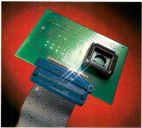
The first low-profile s.m.c. incorporating all of these features is a 34-way product. Intended as a sampling product for examination, test and evaluation, it will be followed by a complete family based on the new concept. Versions already in the pipeline include double-sided connectors and mother-daughterboard types. The design results in a 60% space saving compared with, for example a 96-way DIN equivalent cable interconnection or mother daughterboard connector.
Amphenol recognizes that within the PCB industry the need will remain for existing interfaces and, with this in mind, has developed s.m.t. versions of standard connectors such as headers, sockets, 57 series, D-type and DIN41612. However the company also believes that a new approach is essential to meet specific s.m.t. needs and that by working closely with PCB equipment manufacturers, by using new materials and new contact technology, it has got the basic concept right. There is no doubt it can be developed to meet the spectrum of s.m.t. interconnection requirements, and Amphenol is hoping that it will lead to the generation of new standards idealized to s.m.t.
------------
Also see: Hadamard versus Fourier transformation
==========
(adapted from: Wireless World , Jan. 1987)