The greater operational speed and simplicity of the Hadamard method is more suitable for use with microprocessors and ideally suited for real-time signal processing of speech.
by MARK S. VARNEY
Fourier analysis fits a series of sinusoid al waveforms to original data. Its transform algorithm requires a sine and cosine look-up table and special multiplication routines, adding greatly to the time taken to complete the transformation calculation. Sinewaves are used because they produce the same form on integration or differentiation, and linear systems give sinusoidal outputs for sinusoidal inputs.
It is equally possible to use any other waveform, so long as it can be described mathematically. All transforms are based on the fact that two linear combinations of two numbers contain the same information as the original numbers. Hadamard trans formation (HT), for instance, involves the use of rectangular waves (otherwise known as Walsh functions) of differing periods and phases. The special advantage of the Hadamard method is that the wave has values of either +1 or -1 and so only additions or subtractions are necessary- making it an ideal algorithm for writing on a computer, particularly eight-bit microprocessors such as the Z80 and 6502 which do not have hardware multiply features and would re quire additional code just for multiplying two eight-bit numbers.
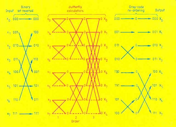
Fig.1. Steps involved in an eight-point Hadamard transform include binary
bit-reversal, butterfly calculations of the transform itself, and Gray
code reordering. Circles represent intermediate products, solid lines
represent additions, dashed lines represent subtractions, and arrows
represent reordering.
MATRIX ALGEBRA
The Hadamard matrix H of order n is an nxn matrix of plus and minus ones, whose rows and columns are orthogonal to one another. The smallest order Hadamard matrix is two,

... and by limiting the order to an integral power of two, symmetrical matrices will be obtained, for example

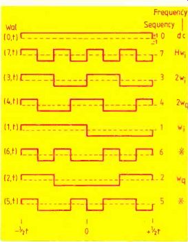
Fig. 2. Walsh, or switching, functions used in the eight-point Hadamard
transform are denoted by their frequency and phase angles (i=in-phase,
q=quadrature). The function that crosses the time axis i times is called
the ith Walsh function and denoted by Wal(i,t). Those denoted by * are
not regular square waves and have no exact physical representation.
==========
PROGRAM 1. 8086 assembly language version of the fast Hadamard transform uses the FIG-Forth assembler and Forth variables to hold current values of the loop counters, etc. Binary bit-reversal is the same as for the FFT, and the Gray code reordering is not included for brevity. The 16-bit data is assumed to be in two's–complement.
Due to circumstances beyond our control we are unable to include the programs in this issue. They will appear in next month's issue, but readers in a hurry may obtain a copy from the editorial office.
==========
Because these forms of the Hadamard matrix are orthogonally symmetric, the procedure to compute the forward and reverse trans form are basically the same, as with the Fourier transform. The one-dimensional Hadamard transform of a real signal may be defined as
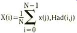
... where X(i) is ith (normalized) Hadamard coefficient, x(j) is jth signal point, and Had(i,j) the ith Hadamard function.
Like the fast Fourier transform (FFT), the Hadamard can be computed `in-place' in order to save precious memory space. Similarly, the structure of the FFT can be exploited to give an algorithm for the fast Hadamard transform (FHT) without using complex numbers. Moreover, by integrating the normalization factor. 1/N, into the algorithm, the size of the data block will be limited only by the available ram. The in-place method stores intermediate pro ducts from the butterfly products in the locations of the input samples, without the need for auxiliary storage. However, the transformed coefficients are then in their natural form (not in order of increasing sequency). To obtain the ordered sequence, the coefficients are firstly bit-reversed as in the FFT either before (time), or after (frequency) the transformation, and finally re arranged with respect to a Gray code permutation (Fig.1). In effect, the original signal waveform is multiplied by each of eight waves as in Fig.2, which correspond to each row of the eighth-order Hadamard matrix.
The analogy with phase-sensitive detection is clear enough. For instance, the d.c. component is just the summed average of each of the original points multiplied by 1, the first waveform, labeled d.c. The in-phase and quadrature components merely use a single frequency wave shifted in phase by 90°. The first harmonic uses the fifth labeled w0, the 90° out-of-phase component the seventh waveform, or wq and so on for the second, fourth, etc harmonics.
SYNCHRONOUS SIGNAL DETECTION
In an analog lock-in amplifier, a sinusoid al input signal Asin (w_0+phi) of amplitude A, angular frequency w° and phase angle 9 is actually multiplied by a square wave of unit amplitude and angular frequency w. The technique is however limited to the measurement of only one frequency at one phase angle. The principle of operation is of a binary nature- it involves multiplying successive points in the waveform by +1 and -1, i.e. alternately adding and subtracting each point. The digital version of this allows the simultaneous acquisition of the fundamental and subsequent harmonics, and the in-phase and quadrature components.
To extract information from a specific frequency and at a specific phase angle from 2^N input data points, a total of 2x2^N additions and subtractions are needed, i.e. 2^N at two orthogonal phase angles. For N different frequencies the number is 2Nx2^N. As a consequence of the Nyquist limitation, in formation on only N-1 frequencies can be extracted from 2^N points, that is at n=0,1,2,...,N-2. Digital synchronous detection of both the in-phase and quadrature components at N-1 frequencies would re quire 2(N-1)x2^N operations, whereas the Hadamard transform only requires Nx2N.
Thus, another advantage of the Hadamard transform over straightforward digital detection is a factor of 2(N-1)/N, which approaches 2 as the size of the data array increases.
There is no dispute that the FHT is a much faster method that the FFT by up to two orders of magnitude in my experience.
However, although the fast algorithm has been used in this article, the slow version is just as simple to write and implement. It would even be possible by simple extension of the above ideas to write an algorithm to determine only those frequencies of interest, and increase the speed of calculation still further.
MULTIPLEX FREQUENCYANALYSIS
A disadvantage of this technique is, however, that it can be more restrictive in the choice of measurement frequencies that can be multiplexed. In fact, all the integral frequencies are an exact power of two i.e. 0,1,2,4,8,16,etc. The other coefficients in between these frequencies are not true regular square waves, and cannot represent actual frequencies but they are necessary in the. calculation of both the forward and reverse transforms.
A frequency interpretation can be given to the whole of the Hadamard matrix. Along each row in Fig.2 the "frequency" is represented by the number of changes in sign, the term "sequency" has been used instead to describe frequency domains. It is possible to construct a Hadamard matrix of order N=2N that has (sequency) components at every integer from 0 to N-1. This may be of consequence to those who wish to avoid (or promote!) the effects of intermodulation between frequencies. However this is not such a disadvantage in areas such as speech recognition since only the major coefficients would be used to store the original voice data, and be used in later speech reproduction. The `frequency' data would not be used as such; that information is held in a number of these coefficients and these can be used to mathematically reconstruct the original waveform.
SPEECH RECOGNITION
As part of an experiment to test the applicability of the Hadamard transform, a small routine was written around the basic FHT algorithm (program 1) to input 10000 samples of speech in one second. The FHT was then used to transform 10 consecutive blocks of 1000 points into the frequency domain. A proportion of the major coefficients from each block were then stored in memory and used to reconstruct the original speech waveform and played through the internal speaker of an Apricot Xen. The program was run interactively through the keyboard within a Forth kernel.
First results found that the reconstruction of certain words containing the phonemes /1/, /w/ or /r/ were difficult to distinguish. Subsequent attempts increasing the number of coefficients from 16 to 32 or 64, enabled better audio resolution of he phonemes. There are still difficulties at the time of writing- for instance, the phonemes /th/, /g/ and /p/ are difficult to distinguish, and appear to depend on the exact instant when sampling is started. However, as a first approach the FHT technique gives excellent results and is capable of analyzing speech or voice data in real time. An interesting little diversion was to shift the transformed data up in frequency, and then playback the `Mickey Mouse' version of the original speech! The FHT technique has also been used in an Apricot Xen to control an electrochemistry module that transmits a multi-harmonic signal to an electrode immersed in a solution containing species that will react at particular potentials. The return of the signal through special potentiostat circuitry contains the (stimulated) response of the species and can be defined by frequency response analysis. Different species and electrode materials change and impedance of the system in predefined ways and can be used as such to identify the processes and mechanisms at the electrodes. FFT software was used in the past, but by changing to the FHT there has been a substantial decrease in the time taken to perform all the necessary calculations without loss in information content.
The same should be true of many other areas that use transforms, such as image coding, video techniques, speech and object recognition, radar and radio and data trans mission and compression. Because of the general complexity of the FFT algorithm a suitable alternative has been found that is simpler to code, occupies less memory, does not resort to complex number notation, and is considerably faster in operation. There are other transforms, and some of these will undoubtedly be better than the FHT for certain cases, but this article demonstrates that the FFT is not the only transformation routine available, and that it is possible to ...
----
Gray codes are not natural codes for computers. They were first developed for use on shaft encoders, or for work with rotating parts where the angle of rotation had to be controlled accurately. It has the property that only one bit in the binary code changes from one transition to another. The rule is:
- begin with all zeros,
- always change the single l.s.b. that gets to the next state.
Gray codes can be generated with any number of bits.
The machine-code routine to do this is rather complicated, but a Fortran subroutine looks like.
SUBROUTINE GRAY(M,N,X) DIMENSION X(N) C N = 2**M = number of samples N2=N/2 N4=N/4 DO 1 I=1,M-1 INT=2**(I-1) DO 2 L=1,INT DO 2 J=1,N4 IY=N2+J+(L-1)*N/INT IX=IY+N4 Z=X(IX) X(IX)=X(IY) 2 X(IY)=Z N2=N2/2 1 N4=N4/2 RETURN
-----
.... tune a microcomputer to work in, or approach, real-time analysis.
Mark Varney obtained his doctoral degree at Liverpool University in chemical oceanography. He has spent three years in postdoctoral research and two years as director of his own research consultancy, designing and developing analytical instrumentation. In 1986 he joined the Oceanography Department at Southampton University where he carries on this work and also lectures in marine organic chemistry.
------------
Also see: Two novel oscillators
==========
(adapted from: Wireless World , Jan. 1987)